Note: Descriptions are shown in the official language in which they were submitted.
20~343~
OUTPUT }~OPPBR APPARATU8
Backgroun~ of the Invention
The present invention relates to an output hopper
apparatus receiving cards from processing stations and
transferring cards onto sorted and ordered stacks. Card
output hopper mechanisms are widely used in systems for
embossing and processing cards requiring stacking and
sorting. The output hopper apparatu~ receives cards from
the processing modules and stacks the cards on a proper
card stack in proper sequence.
Prior methods of stacking and sorting processed
cards have many associated problems. Cards often jam in
the mechanism or are stacked in the wrong order. This
often causes problems in identifying and processing the
cards. In addition~to clogging the mechanism with jammed
cards, jamming damages the cards. This requires re~
embossing of the damaged cards and additional delays and
costs. Prior methods of stacking used deflecting arms for
deflecting only. The cards are not driven by the
deflecting arms onto the card stacks. Cards are pushed
onto the card stacks by additional driving rollers or by
the next card. This method leads to cards being inserted
in the stack in the wrong order and causes problems in
further processing.
The present invention addresses these problems
associated with stacking and sorting processed cards. It
is apparent that an improved mechanism and method for
receiving processed cards and properly sorting and
stacking the cards are needed. The present invention
solves these problems and others associated with~stacking,
and sorting processed cards.
8ummarY o~ the Invention
In the present invention, plastic cards being
processed in a card embossing system are carried through
card processing modules on a card transport to an output
position where output hopper feed rollers receive cards
- from a preceding module. Sensors along the card transport
.., :'~ ..',.,: '~.'.
" ~, ,
::.:~ . ~ .,
ZQ~)3~36
path determine the status of each Gard as acceptable or
rejected. The status is used logically, wherein output
hopper deflecting means direct received cards either to an
accepted card tray or a reject card tray. In a second
embodiment, cards may also pass directly through the
deflector along a third direction for additional
processing or sorting. The deflecting means separate the
accepted card tray from the reject card tray. If a second
embodiment is used in which a slot runs through the length
of a deflector allowing cards to pass along a third
direction, additional card trays may also be used.
Cards feed through a set of rollers to the
deflecting means. The deflecting means comprise a
pivotally mounted deflector arm driven by a stepper motor
or solenoid for moving the deflector into a position for
accepting cards and deflecting the cards toward the proper
stack. The deflector acts to deflect cards and also
serves as card driving means for driving the cards into
the card trays. By driving the cards onto an end of the
card stack rather than just deflecting cards toward the
tray, cards will not be stacked out of sequence, as when
cards are only deflected, and problems arising from cards
being stacked in improper order are avoided.
In operation, the deflector is moved to one side
of the center line of the feed rollers. Cards are fed to
the deflector and directed along side and away from the
deflector. After the trailing edge of the card passes a
photocell between the feed rollers, the deflector begins
its motion after a built in time delay. The deflector
then rotates toward the proper card tray, sweeping the
card past a card stack retainer into a card tray and onto
the card stack. The feed rollers also help to push the
cards onto the card stack by pushing the trailing edge of
the card around the periphery of the roller and toward the
card stack. The receiving angle and path swept by the
deflector is adjustable for various types and thicknesses
of cards by adjusting the number of steps moved by the
:: ...
z0a~3436
stepper motor or by adjusting the solenoid position and
the travel of its plunger, thereby varying the receiving
angle and angle of rotation by the deflector. For driving
cards into the opposing reject tray, the deflector motion
is reversed to a mirror image of the motion associated
with driving cards into the acceptable card tray.
Cards are maintained in their stack position by
a retainer located at the deflector end of the card tray,
and a tensioning member or weight positioned at the
opposite end of the card tray. The tension between the
retainer at one end and the tensioning member at the other
end of the card tray maintains the cards in a stack so
that adjacent cards remain in contact, avoiding problems
associated with improper sequencing and loose cards.
In a second embodiment, the defIector stops at
three receiving positions for deflecting cards. In
addition to moving to one side or the other for deflecting
cards into the trays, the deflector stops at a center
position. A slot running lengthwise through the deflector
directs the card straight through the deflector.
Additional rollers then drive the card onto another
deflector or additional processing stations. It can be
appreciated that a series of deflectors may be arranged in
this manner, providing for deflecting and driving cards
onto a number of card stacks, thereby increasing holding
capacity and enabling greater diversity in card
classification.
These and various other advantages and features
of novelty which characterize the invention are pointed
out with particularity`in~the claims annexed hereto an*
forming a part hereof. However, for a better
understanding~ of the invention, its advantages, and
objects obtained by its use, reference should be made to
tlle drawings which form a further part hereof, and to the
accompanying descriptive matter, in which there is
illustrated and described preferred embodiments of the
invention.
Z0~3aL3~
.
:: :., ,~
Brief Description of the Draw~ngs
In the drawings whersin like reference numerals
and letters indicate corresponding elements throughout the
several views:
Fig. lA is a block diagram of a card embossing
apparatus implementing an output hopper apparatus of the
present invention;
Fig. lB is a block diagram of the output hopper
control logic according to the principles of the present
invention; -
Fig. 2 is a perspective view of an output hopper
apparatus of the present invention;
Fig. 3 is a top plan view illustrating an output
hopper apparatus as shown in Fig. 2;
Fig. 4 is a bottom plan view illustrating an
output hopper apparatus shown in Fig. 2:
Fig. 5 is a top plan view of a detail
illustrating an output hopper apparatus shown in Fig. 2, ; - -
showing the deflecting means in its home position and a
card being fed toward the deflecting means;
Fig. 6 shows a top plan view of the deflecting
means shown in Fig. 5, wherein the deflecting means is
rotated partially across the path of its motion to drive
25 a card toward the accepted card tray; -
Fig. 7 is a top plan view of the deflecting means ~ ~-
shown in Fig. 5, showing the deflecting means fully moved
across the path of its motion to a position wherein a card - ~:
is directed onto the accepted card tray; ;
~ . - .
i 1 Fig. 8 !is la top plan view of the deflecting means
shown in Fig. 5, showing the deflecting means in a
position for receiving a card to be deflected onto the
.. ..
reject card tray;
Fig. 9 is a top plan view of the deflecting means
shown in Fig. 5, showing the deflecting means moving
partially across its path to drive a card onto the reject
card tray;
.; .~ '~: `..
"
: ~ : ., ~ ~;:
20~)3436
.. , , . :,
-
Fig. 10 is a top plan vîew of the deflecting
means shown in Fig. 5, showing the deflecting means fully
driven across the path of its motion to drive a card onto - -
the reject tray;
5Fig. 11 is an elevational view of a second
embodiment of an output hopper apparatus in accordance
with the principles of the present invention illustrating
a deflecting means comprising slotted deflectors having
three receiving positions;
10Fig. 12 is a top view of a second embodiment
taken along line 12-12 of Fig. 11, illustrating the
deflecting means in a receiving position for passing a
card straight through;
Fig. 13 is a top view of a second embodiment
15taken along line 12-12 of Fig. 11, illustrating the first
deflector in a position for driving the card onto a card
stack and also illustrating in phantom the first deflector
in a receiving position for deflecting the card toward a
side tray;
20Fig. 14 is a top sectional view of a second
embodiment taken along line 14-14 of Fig. 11, illustrating
the gear arrangement below the rollers;
Fig. 15 is a top sectional view of a second -~
embodiment taken along line 15-15 of Fig. 11, illustrating
the pivotal roller sets; and
Fig. 16 is a top sectional view of a second -
embodiment taken along line 16-16 of Fig. 11, illustrating
the motor and drive belt arrangement. ^^~
~ . ,:,, ~, ....
30Detai~le Desoription of the~Present Invention
In Fiq. lA a block diagram is shown of an
embossing and printing apparatus implementing an output
hopper apparatus according to the present invention. A
card embossing and printing apparatus shown generally at ^~
20 comprises card processing stations 22 which perform
various printing and embossing operations on plastic ~ ~ -
cards. Cards are input by means of an input hopper 24, ;~
'' ~ ' '' ~'.
:
Z0~:13a~36
~;i 6
and are then processed along a card transport path and
delivered to an output hopper 26. The embossing
operations are programmably controlled by a microcomputer
28 having a memory 32. Specifications and requirements
are input into the microcomputer 28 by means of a user
terminal 34. Adjustments may then be made to the
processing operations for the particular needs of the
user.
As shown in Fig. lB, deflecting means 38 is
controlled by the output hopper internal logic control 25.
Status of each card as rejected or acceptable is assigned
as the card is processed. As the card passes photocell
~ensor 68 (shown in Figure 2), the logic control moves the
deflecting means to a receiving position in accordance
with the status of the card.
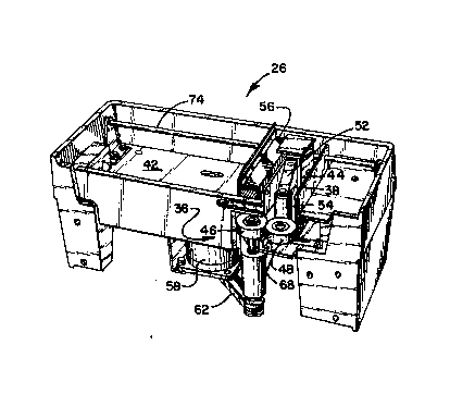
As shown in Fig. 2, an output hopper 26 includes
feed means 36 wherein cards are received by the output
hopper 26. Cards pass to the deflecting means 38 and then
to either an accepted card tray 42 or a re~ect card tray
44.
As shown in Fig. 3, feed means 36 comprise a
drive roller 46 and idler roller 48. A photocell 68 is
located below the feed means 36 for detecting passage of
cards through the feed means 36. The drive roller 46 is
driven by a motor 58 and a drive belt 62. The drive
roller 46 engages the idler roller 48 by friction along
the nip of the rollers. The rollers 46 and 48 engage
cards by friction of the rubber rollers against the card
surface. In this manner, the idler roller 48 rolls along
:: : ~.. .;;:,
with a card as the!card~is passed through,the feed means
36. Friction against the drive roller 46 re-engages the
idler roller 48 after the card has passed through the feed
means 36, thereby driving the idler roller 48 when cards
are not present between the idler roller 48 and drive
roller 46.
After a card has passed through the feed means
36, the card engages the deflecting means 38 comprising a
: :. ' .
:
::
:: , .: .
2003a~36
deflector 52 having a deflector roller 54 at its tip. The
roller 54 decreases friction against cards and lessens
scratching of card surfaces. As shown in Fig. 4, a
solenoid 88 drives the deflector 52 through linkage 92
tensioned into a home position by spring 86. When a card
has passed through the feed means 36, the card engages the
deflector 52 in a receiving position for accepted cards.
If sensing determines that a card has a rejected status,
the deflector 52 is moved to an opposite position for
receiving rejected cards. As a card passes through the
feed means 36, it is detected by photocell 68. The
deflector 52 rotates to a receiving position for
deflecting the card to one of the trays, the receiving
position determined by whether the card has an acceptable
or rejected status as shown in Fig. lB . After a card
passes by photocell 68, a built in delay expires before
the deflecto~ 52 rotates and pushes the card at the
correct instant. When pushed into the accepted tray 42,
cards are held in place by a tension block 56 and a
retainer 64, or in the reject tray 44, cards are held by
a back wall 66 and retainer 64. A top plate 72 prevents
cards from misaligning upward upon movement onto a card
stack. The tension block 56 is maintained in position by
a guide rod 74 and tensioned against the card stack by a
spring 78 which is coiled onto a reel 76. Circuitry 84
controls the electric motor 58 and the solenoid 88 for
actuating the deflector 52 after sufficient delay time.
As shown in Fig. 5, a card 82 enters the output
hopper 26 through feed means 36. The card is gripped in
the nip of the drive roller 46 and the idler roller 48.
As shown in Fig. 6, when the card 82 is driven through the
feed means 36, the card's passage is detected by the
photocell 68. The deflector arm 52 rotates so that
deflector roller 54 pushes the card 82 towards card tray
42. The trailing edge of the card 82 is also rolled along
the periphery of the drive roller 46 until engaging
retainer 64. The card 82 bows slightly as contact is
20(33~i36
maintained with both roller 46 and deflector 52. The
deflector 52 continues rotating and pushes the card 82
past the retainer 64, driving the card 82 onto the stack
as shown in Fig. 7. The card 82 is stacked and tensioned
by a block 56 and the retainer 64. The retainer 64
insures that stacked cards do not fall back onto the
deflecting means 38 and also insures that the cards remain
in correct sequence. The deflector 52 then moves back to
its receiving position and is ready to accept the next
card.
As shown in Fig. 8, when a card has a rejected
status, the deflector 52 moves toward the accepted card
tray 42 to a reject receiving position. The card 82
enters the feed means 36. The card 82 is driven onward
until engaging the opposite side of the deflector 52.
When the trailing edge of the card 82 has passed through
the photocell 68, the deflector 52 is actuated so that the
deflector roller 54 pushes the card 82 toward the reject
card tray 44.
As shown in Fiq. 9, the deflector 52 moves toward
the reject card tray 44, using the deflector roller 54 to
push the card 82 toward the reject card tray 44. The
trailing edge of the card 82 is pushed toward the reject
card tray 44 by the periphery of the idler roller 48 which
is being rolled by friction between the idler roller 48
and the drive roller 46. The card is then pushed past
retainer 64, as shown in Fig. 10, and onto the reject card
stack against a back retaining wall 66. The deflector 52
is then rotated to its accepted receiving position and
ready for the next card.; ~
~econd Embo~iment
As shown in Figs. 11-16, the output hopper
apparatus 100 comprises a second embodiment having a
plurality of deflectors. As shown in Fig. 12, the output
hopper apparatus 100 includes a first deflector 102 and a
second deflector 104. The deflectors 102 and 104 are
.
'
20~)34~f~
slotted so th~t cards 126 may pass through the deflectors
when maintained in a straight-on position as shown in Fig.
12. The deflectors 102 and 104 also rotate for deflecting
cards 126 onto card trays 114, 116 or 118.
In operation, card 126 is received at feed
rollers 106 and 106a as shown in Fig. 12. The card 126
may be passed straight through the deflector 102 in a
receiving position as shown in Fig. 12. The card 126 is
fed by rollers 106 and 106a through deflector 102 to
10 rollers 108 and 108a which feed the card 126 to the second
deflector 104. The card 126 may then be passed straight
through deflector 104 as shown in Fig. 12 to rollers 110
and llOa and fed out through rollers 112 and 112a.
The 'deflectors 102 and 104 also rotate to a
15 receiving position às shown at A in Fig. 13. The card 126
is fed by rollers 106 and 106a to the deflector 102 in a
receiving position as shown at A. The card 126 engages
the deflector 102 in a receiving position and is deflected
toward tray 114. The deflector 102 is then rotated
towards a position as shown at B thereby pushing the card
126 towards the card tray 114. The trailing edge of the
card 126 is rolled around the periphery of roller 106a
thexeby aiding in directing the card 126 towards the card
tray 114. The deflector 102 continues its motion until
25 the card 126 passes by retainer 124 and pushed onto the
card tray 114ias shown at position B in Fig. 13. Cards
126 are retained in the card trays 114, 116 and 118 by
weights 120 engaging the backside of the cards 126 and by
retainers 124 engaging the frontside of cards 126. The
30 weightsj120 areislidably'mounted on rails~122 so that as
cards 126 are added, the weight 120 slides along rail 122
as the card stack expands. The weight 120 maintains the
cards 126 in a tightly grouped stack in this manner by
pressing each card against adjacent cards in the stack.
Alternatively, the card may be fed to tray 116.
The deflector 102 is moved toward tray 114 for receiving
a card mirroring the position shown at A. The card 126
; - ~:
'~ '' ~,' ', ~ '
', ~'',
~0~ 3~
engages the deflector 102 and is pushed as deflector 102
rotates toward tray 116 mirroring the motion for directing
the card toward tray 114. The trailing edge of the card
126 rolls around the periphery of roller 106 and is pushed
past retainer 124 onto tray 116 engaging a weight 120.
The deflector 102 moves to a position mirroring that shown
at B for driving the card 126 into tray 116.
Cards 126 may also be directed into tray 118.
The card 126 is fed through deflector 102 in a straight
receiving position as shown in Fig. 12 to rollers 108.
Deflector 104 is then moved to a receiving position
identical to that shown at A in Fig. 13. The card 126
engages deflector 104 and is deflected towards card tray
118. Roller 108a rolls the trailing edge of the card 126
around the periphery of roller 108a towards card tray 118.
The deflector 104 then moves across and drives the card
126 past retainer 124 to a position as shown at B for
deflector 102 in Fig. 13 and driving card 126 onto the
card tray 118.
Cards 126 may also be passed straight through the
output hopper apparatus 100. The deflectors 102 and 104
are maintained in a straight receiving position as shown
in Fig. 12. The cards 126 are then fed by rollers 106 and
106a to rollers 108 and 108a through deflector 104 to
rollers 110 and llOa and finally out through rollers 112
and 112a.
As shown in Figs. 14-16, the rollers are mounted
on shafts so that each roller is gear driven and there are
no idler rollers. As shown in Fig. 14, the rollers 106
and 106a mount on shafts;142 and 142a having gears 128~and
128a contacting each other. Similarly, rollers 108 and
108a rotate about shafts 144 and 144a and maintain meshing
between gears l30 and 130a: rollers 110 and llOa rotate on
shafts 146 and 146a maintaining meshing between gears 132
and 132a. Rollers 106, 108 and 110 are driven by belt 194
as shown in Fig. 16. Belt 194 engages pulleys 196, 198
and 200 is also guided by pulley 206. The belt 194 is
Z0~134~6
driven by a motor 192 so that all rollers maintain the
same speed. Rollers lO~a, 108a and llOa are driven by the
gear pairs. The gear pairs 128-128a, 130-130a and 132-
132a are always meshed so that all rollers are gear driven
and not idler rollers. Shafts 142a, 144a, and 146a are
mounted on arms 158, 160 and 162, respectively. The arms
158, 160 and 162 mount on pivot 147 and deflector shafts
148 and 150, respectively. The arms are rotatable so that
the shafts 142a, 144a and 146a pivot in slots 178, 180 and
lo 182, respectively. In this manner, the rollers move
slightly apart so that a card 126 may pass between the
roller pairs. The meshing between gear teeth is
maintained between the belt driven gears 128, 130, 132 and
the associated shaft gears 128a, 130a, 132a by biasing
15 from springs 152, 154 and 156, respectively. The
separation of the gears is limited by the arms 158, 160
and 162 engaging stops 166, 168 and 170, respectively.
Motion in the opposite direction is limited by the rollers
106-106a, 108-108a, and llO-llOa engaging.
The final set of rollers 112 and 112a mount on
shafts 172 and 172a and are held on spring loaded pivot
arms 164 and 164a as shown in Fig. 15. Rollers 112 and
112a are driven by gears 140 and 140a through gears 138
and 138a, respectively, mounted on shafts 174 and 176.
25 Gear 136 mounted on shaft 176 above gear 138a is the
driving gear for rollers 112 and 112a. An idler gear 134
mounted on idler shaft 175 transfers motion from gear 132
to gear 136, driving shaft 176. In this manner, gear
contact is constant and the driving of shaft 146 by belt
30 194 around pulley~200l as shown in Fig.~16 drives the
entire roller set llO-llOa and 112-112a. Spring 173
tensions pivot arms 164, 164a together so that contact is
maintained between rollers 112 and 112a.
It iæ to be understood that even though the above
numerous characteristics and advantages of the invention
have been set forth in the foregoing description, together
with details of the structure and function of the
~ ;, ~ ,:
: , ~:
20~343~ ~
" ' .- '
12
invention, the disclosure is illustrative only, and :
changes may be made in detail, especially in matters of ~ `~
shape, size and arrangement of parts within the principles
of the invention, to the full extent indicated by the
5 broad, general meaning of the terms in which the appended `~
claims are expressed. :`~
, ~ ,.,
,, : ~: .:
', ,~ , ' ~,:
:, ~'''
" ~,'.",`
', '~ ',
.
..
-: ,. ...
. ,
:- :. ...
: ..,. ",, :" ;.
: ~ "'~
, ~,; ~ ~,
;: -, . - ;,;,: :,
. "-~ ;, "' '`'
': ~
:' . ~ :` ~: ' ~.,
;'',-' ". `; ''