Language selection

Search

Patent 2003895 Summary

Third-party information liability

Some of the information on this Web page has been provided by external sources. The Government of Canada is not responsible for the accuracy, reliability or currency of the information supplied by external sources. Users wishing to rely upon this information should consult directly with the source of the information. Content provided by external sources is not subject to official languages, privacy and accessibility requirements.

Claims and Abstract availability

Any discrepancies in the text and image of the Claims and Abstract are due to differing posting times. Text of the Claims and Abstract are posted:

  • At the time the application is open to public inspection;
  • At the time of issue of the patent (grant).
(12) Patent: (11) CA 2003895
(54) English Title: FILTRE INTRA-NASAL
(54) French Title: INTRANASAL FILTER
Status: Expired and beyond the Period of Reversal
Bibliographic Data
Abstracts

English Abstract


A nasal filter positionable within a nostril having a
nasal vestibule merging with a nasal passage of reduced
cross-sectional dimension relative to the nasal
vestibule. The filter comprises a body of resilient
synthetic spongy material which yields upon radial
compression to assume a compressed form of reduced,
substantially uniform diameter permitting insertion into the
nasal vestibule. The body further has a cross-sectional
dimension when uncompressed such that when the filter has
been inserted in the nostril and the spongy material has
expanded radially, the body snugly fits within the nasal
vestibule and causes an enlargement of the nasal passage.


Claims

Note: Claims are shown in the official language in which they were submitted.

I claim:
1. A nasal filter positionable within a nostril for filtering
air pollutants nasal air, said nostril having a nasal vestibule
merging with a nasal passage of reduced cross-sectional dimension
relative to said nasal vestibule said filter comprising a body
of resilient synthetic spongy material which yields upon radial
compression to assume a compressed form of reduced diameter
permitting insertion into said nasal vestibule and further
having a cross-sectional dimension when uncompressed such
that when said filter has been inserted in said nostril and
said spongy material has expanded, radially, said body snugly
fits within said nasal vestibule and causes an enlargement of
said portion of said nasal passage.
2. A nasal filter according to claim 1, wherein said body of
synthetic spongy material has heat and moisture exchange
properties.
3. A nasal filter according to claim 1, wherein said body of
synthetic spongy material has an air flow resistance.
4. A nasal filter according to claim 1, wherein a pharmaceu-
tically active substance is embedded in said body of synthetic
spongy material at a location such as to be disposed in said
nasal vestibule when said filter is inserted in said nostril,
for dispensing said pharmaceutically active substance in said
nasal air.
5. A nasal filter according to claim 1, wherein an active
substance having a stimulating effect on olfactory receptors
is embedded in said body of synthetic spongy material at a
location such as to be disposed in said nasal vestibule when
said filter is inserted in said nostril, for dispensing said
active substance in said nasal air.
6. A nasal filter filter according to claim 1, wherein
said synthetic spongy material is a presterilized and anti-
allergenic spongy material.
7. A nasal filter according to claim 1, wherein said syn-
thetic spongy material is electrostatically charged.

Description

Note: Descriptions are shown in the official language in which they were submitted.


BACKGROUND OF TNE INVENTION
20 0 38-9 5
This invention relates to a nasal filter more particularly
to flexible filters adapted to be inserted in the nostrils
of the nose Eor filtering nasal air.
Nasal filters are known in the art, for example, in U.S.Pat.
2,426,161 2,433,565 2,526,586
2,535,155 2,674,245 2,890,695
3,463,149 3,747,597 3,802,426
3,884,223 3,905,335 4,030,491
4,052,983 4,280,493
and the international application WO 85/01216
The filtering devices described in the above patents, hotaever,
are deficient for one or more of the following reasons: they
do not provide a secure fit within the nostrils; they contain
rigid connections which can be painful; they are not readily
replaceable and they generally obstruct nasal air flow, thus
providing difficulty in breathing.
SUMMARY OF TiiE INVENTION
It is accordingly an object of this invention to overcome
the above drawbacks and to provide-an improved nasal filter
which is comfortable to wear, permits easier k~reathing and
yet can effectively filter dust pollen and stnoke particles.
In accordance with the invention, there is thus provided a
nasal filter positionable within a nostril having a nasal
vestibule merging with a nasal passage of reduced cross-
sectional dimension relative to the nasal vestibule. The
filter comprises a body of resilient synthetic spongy
material which yields upon radial compression to assume a
compressed form oE reduced, substantially uniform diameter
permitting insertion into the nasal vestibule. The body
further has a cross-sectional dimension when uncompressed
such that when the filter has been inserted in the nostril
and the spongy material has expanded radially, the body
snugly fits within the nasal vestibule and causes an
enlargement of the nasal passage.
.9

2
2003895 z
According to a further prefered embodiment of the invention,
an actAve substance having a stimulating effect on olfactory
receptors or a pharmaceutically active substance is embedded
in the body of synthetic spongy material at a location such
as to be dzspo---ed in !;he nasal vestibule when the filter
is inseztec3 in the nostril, for dispensing the active
substance in thc nasal aAx.
By causing an enlargement of the nasal passage, the nasal
filteJ.; of the inlJention permits easier breathing.
DRIEF DESCRIPTIGtd OF THE DRAWINGS
Further features and advaritages of the invention will become
more readily apparerit from the following description of
preferred embodinients as illustrated by way of examples in
the accompanying drawings, in i-liich:
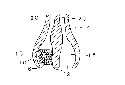
FIG.1 is an elevational section view of a nasal filter
accordiiig to a first ernbodiraent of the invention, shown
just before ex,par-sion in a nostril;
FIG.2 is a view siniilar to FIG.I after full expansion
of the synthetic spongy material and illustrating t'lre
enlargement of the nasal passageF
FIG. 3 is a view similar to F1C.2 showing schematically
heat and moi.sture excliange during expiration;
FIG. 4 is a view similar to FIG.2 showing schematically
heat and moisture exchange during inspiration;
FIG. 5 is a view similar to FIG.2 showing schematically
air flow resistance during expiration.
FIG. 6 is a schematic side sectional view of a nasal filter
according to a fourth embodiment of the invention, sholqn
positioned i=tithin a nostr.il.

2003895 zl
DESCRIPTION OF PREFERRED
EMBODIMENTS
Referring first to FIGS.1 and 2, there is illustrated an
intra-nasal filter 10 positionable in each nostril 12 of
one's nose 14, and comprising a body 16 of resilient
synthetic spongy material which offers no resistance to
air flow, is smooth for the mucous membrane, anti-
allergenic, electrostatically charged and yet can effec-
tively filter air pollutants. The synthetic spongy
material is also presterilized. As shown, each nostril
12 has a nasal vestibule 18 merging with a nasal passage
20 of reduced cross-sectional dimension relative to the
nasal vestibule 18.
By squeezing the filter 10, the body 16 of synthetic
spongy material will yield upon radial compression to
assume a compressed form of reduced diameter (shown in
FIG.1), permitting insertion of the body 16 into the
nasal vestibule 18.
As illustrated in FIG.2, the body 16 of synthetic spongy
material further has a cross-sectional dimension when
uncompressed such that when the filter 10 has been posi-
tioned within the nostril 12 and the spongy material has
expanded radially, the body 16 snugly fits within the
nasal vestibule 18. The presssure exerted by the body 16
on the mucus membrane is sufficient to maintain the filter
in place even through brutal expirations. Moreover,
the pressure created by the radial expansion of the spongy
material in the nasal vestibule 18 is such as to cause an
enlargement of the portion 24 of the nasal passage, thereby
permitting easier breathing. The high flexibility of the
spongy material allows it to follow the fast movements of
.the nostrils and its resistance to tearing is such that the
extraction of the filter 10 will not leave any piece of the
spongy material in the nose. Extraction of the filter 10
can be performed simply by pinching and pulling out the
body 16 of spongy material. To limit gradual obstruction
of the filter 19, which may be possible in extremely dusty
areas, one can promote self-cleaning by using the expira-
tor.y air flow.
Since the synthetic spongy material of which is made the
nasal filter 10 illustrated in FIGS.1 and 2 has heat and
moisture exchange properties, the filter 10 can be used as a
heat and moisture exchanger. Thus, the filter 10 has the
capacity to preserve a part of expiratory heat and moisture
50 within the body 16 of synthetic spongy material, as shown
in FIG.3, and to give back part of the expiratory heat and 4
moisture 50 at the subsequent inspiration, as shown in FIG.

4
200389581
The expiratory purse lips technique is shown to patients
having respiratoty problems. It is the most effective
and the easiest way to improve their gas exchanges.
Indeed, the positive pressure resulting from an expira-
tory air flow resistance has repercussions as far as
the alveolar membrane and improves the oxygen diffusion
through, this membrane into the blood. A nasal filter
which automatically causes an accurate and stable expi-
ratory air flow resistance will become an indispensable
prothesis for the handicapped suffering from respiratory
problems.
Moreover, in order to allow a patient to do some respi-
ratory exercices, there is known a device which enables
the patient to breathe in by his mouth through differently
sized holes providing different air flow resistances.
Thus, the patient has to breathe through his mouth as
much as 60 minutes a day, which may irritate the patient.
One can do the same exercices in a more physiological way
with an intra-nasal filter adapted to build up a variety
of inspiratory air flow resistances.
FIG.5 illustrates a nasal filter 200 adapted to provide
an expiratory air flow resistance. As shown, the filter
200 comprises a body 202 of resilient synthetic spongy
material through wich the expiratory air flow will come
up against, causing an expiratory air flow resistance 204.
FIG.6 shows how the nasal filter can be used as a medecine
dispenser which may be especially beneficial to the brocho-
dilators or cortiscosteroid dependents or to anybody who
requires a continous level of drugs in their system (heart
patients, diabetics, contraception, etc). The nasal filter
300 illustrated in FIG.6 comprises a body 302 of resilient
synthetic spongy material in which is embedded a pharmaceu-
tically active substance 304. The substance 304 is positioned
in the body 302 at a location such as to be disposed in the
nasal vestibule 18 when the filter 300 is inserted in the
nostril 12. Upon each inspiration, the pharmaceutically
active substance 304 is dispensed in the nasal air.
Furthermore, this allows a good correlation between demand
and drug delivery. Indeed, if the metabolism is accelerated,
then the breathing rate will increase, thereby delivering
more medecine.
In order to prevent certain foul odours from being detected
by the olfactory receptors, it is also possible to replace
the pharmaceutically active substance 304 by an active
substance having a stimulating effect on the olfactory re-
ceptors corresponding to the undesired family of odours.
For example, one may insert a specific perfume in the nasal
filter 300.
AQ

Representative Drawing
A single figure which represents the drawing illustrating the invention.
Administrative Status

2024-08-01:As part of the Next Generation Patents (NGP) transition, the Canadian Patents Database (CPD) now contains a more detailed Event History, which replicates the Event Log of our new back-office solution.

Please note that "Inactive:" events refers to events no longer in use in our new back-office solution.

For a clearer understanding of the status of the application/patent presented on this page, the site Disclaimer , as well as the definitions for Patent , Event History , Maintenance Fee  and Payment History  should be consulted.

Event History

Description Date
Time Limit for Reversal Expired 2006-11-16
Inactive: Adhoc Request Documented 2006-08-18
Letter Sent 2005-11-16
Grant by Issuance 1999-03-30
Change of Address Requirements Determined Compliant 1999-01-21
Inactive: Office letter 1999-01-08
Inactive: Final fee received 1998-12-17
Change of Address or Method of Correspondence Request Received 1998-12-17
Pre-grant 1998-12-17
Notice of Allowance is Issued 1998-11-06
Letter Sent 1998-11-06
Notice of Allowance is Issued 1998-11-06
Inactive: Application prosecuted on TS as of Log entry date 1998-11-02
Inactive: Status info is complete as of Log entry date 1998-11-02
Inactive: Approved for allowance (AFA) 1998-10-08
Request for Examination Requirements Determined Compliant 1996-09-25
All Requirements for Examination Determined Compliant 1996-09-25
Application Published (Open to Public Inspection) 1991-05-16
Inactive: Office letter 1990-10-08

Abandonment History

There is no abandonment history.

Maintenance Fee

The last payment was received on 1998-10-08

Note : If the full payment has not been received on or before the date indicated, a further fee may be required which may be one of the following

  • the reinstatement fee;
  • the late payment fee; or
  • additional fee to reverse deemed expiry.

Patent fees are adjusted on the 1st of January every year. The amounts above are the current amounts if received by December 31 of the current year.
Please refer to the CIPO Patent Fees web page to see all current fee amounts.

Fee History

Fee Type Anniversary Year Due Date Paid Date
MF (application, 8th anniv.) - small 08 1997-11-17 1997-10-22
MF (application, 9th anniv.) - small 09 1998-11-16 1998-10-08
Final fee - small 1998-12-17
MF (patent, 10th anniv.) - small 1999-11-16 1999-11-01
MF (patent, 11th anniv.) - small 2000-11-16 2000-10-02
MF (patent, 12th anniv.) - small 2001-11-16 2001-10-09
MF (patent, 13th anniv.) - small 2002-11-18 2002-09-30
MF (patent, 14th anniv.) - small 2003-11-17 2003-09-03
MF (patent, 15th anniv.) - small 2004-11-16 2004-09-17
Owners on Record

Note: Records showing the ownership history in alphabetical order.

Current Owners on Record
JEAN-PIERRE ROBITAILLE
Past Owners on Record
None
Past Owners that do not appear in the "Owners on Record" listing will appear in other documentation within the application.
Documents

To view selected files, please enter reCAPTCHA code :


To view images, click a link in the Document Description column. To download the documents, select one or more checkboxes in the first column and then click the "Download Selected in PDF format (Zip Archive)" or the "Download Selected as Single PDF" button.

List of published and non-published patent-specific documents on the CPD .

If you have any difficulty accessing content, you can call the Client Service Centre at 1-866-997-1936 or send them an e-mail at CIPO Client Service Centre.


Document
Description 
Date
(yyyy-mm-dd) 
Number of pages   Size of Image (KB) 
Abstract 1998-09-15 1 18
Description 1998-09-15 4 214
Claims 1998-09-15 1 47
Drawings 1998-09-15 6 89
Abstract 1994-03-04 1 14
Drawings 1994-03-04 1 13
Claims 1994-03-04 1 23
Description 1994-03-04 1 21
Representative drawing 1998-06-17 1 6
Representative drawing 1999-03-24 1 8
Notice: Maintenance Fee Reminder 1997-08-18 1 119
Notice: Maintenance Fee Reminder 1998-08-17 1 131
Commissioner's Notice - Application Found Allowable 1998-11-05 1 163
Notice: Maintenance Fee Reminder 1999-08-17 1 130
Notice: Maintenance Fee Reminder 2000-08-16 1 119
Notice: Maintenance Fee Reminder 2001-08-19 1 131
Notice: Maintenance Fee Reminder 2002-08-18 1 118
Notice: Maintenance Fee Reminder 2003-08-18 1 115
Notice: Maintenance Fee Reminder 2004-08-16 1 119
Notice: Maintenance Fee Reminder 2005-08-16 1 119
Maintenance Fee Notice 2006-01-10 1 172
Second Notice: Maintenance Fee Reminder 2006-05-16 1 118
Notice: Maintenance Fee Reminder 2006-08-16 1 119
Fees 2003-09-02 3 82
Fees 2001-10-08 1 70
Correspondence 1999-01-07 1 7
Correspondence 1998-12-16 1 36
Fees 1998-10-07 1 69
Fees 2002-09-29 1 82
Fees 1997-10-21 1 68
Fees 1999-10-31 1 66
Fees 2000-10-01 1 22
Fees 2004-09-16 1 20
Fees 1996-11-12 3 51
Fees 1995-11-01 1 72
Fees 1994-10-20 1 29
Fees 1993-10-28 1 18
Fees 1992-10-19 1 23
Fees 1992-04-27 1 21
Fees 1992-04-15 1 29
Correspondence 1992-01-26 3 78
Prosecution correspondence 1996-09-24 1 38
Prosecution correspondence 1998-08-25 1 21
Prosecution correspondence 1998-06-21 2 44
Prosecution correspondence 1997-09-07 14 430
Prosecution correspondence 1996-09-24 1 37
Examiner Requisition 1989-10-24 1 25
Courtesy - Office Letter 1996-07-21 1 67
Examiner Requisition 1997-04-03 2 117
Examiner Requisition 1998-01-29 2 82