Language selection

Search

Patent 2004221 Summary

Third-party information liability

Some of the information on this Web page has been provided by external sources. The Government of Canada is not responsible for the accuracy, reliability or currency of the information supplied by external sources. Users wishing to rely upon this information should consult directly with the source of the information. Content provided by external sources is not subject to official languages, privacy and accessibility requirements.

Claims and Abstract availability

Any discrepancies in the text and image of the Claims and Abstract are due to differing posting times. Text of the Claims and Abstract are posted:

  • At the time the application is open to public inspection;
  • At the time of issue of the patent (grant).
(12) Patent: (11) CA 2004221
(54) English Title: APPARATUS FOR HEATING PIPE
(54) French Title: CHAUFFE-CANALISATION
Status: Term Expired - Post Grant Beyond Limit
Bibliographic Data
(51) International Patent Classification (IPC):
  • F16L 53/00 (2018.01)
  • B29B 13/02 (2006.01)
  • B29C 35/04 (2006.01)
  • B29C 35/08 (2006.01)
  • B29C 63/00 (2006.01)
  • F16L 55/18 (2006.01)
(72) Inventors :
  • KIRBY, ALAN CAMERON (Canada)
(73) Owners :
  • CCI THERMAL TECHNOLOGIES INC.
(71) Applicants :
  • ALAN CAMERON KIRBY (Canada)
(74) Agent: GOWLING WLG (CANADA) LLP
(74) Associate agent:
(45) Issued: 1994-11-08
(22) Filed Date: 1989-11-29
(41) Open to Public Inspection: 1991-05-29
Examination requested: 1992-01-20
Availability of licence: N/A
Dedicated to the Public: N/A
(25) Language of filing: English

Patent Cooperation Treaty (PCT): No

(30) Application Priority Data: None

Abstracts

English Abstract


ABSTRACT OF THE DISCLOSURE
An apparatus for heating a length of pipe and/or
sleeve mounted thereon includes a main frame defined by a
pair of posts for mounting on the pipe on each side of the
area to be heated and a guide bar extending between the top
ends of the posts parallel to the pipe; a screw extending
between the posts above the pipe in the use position; a
carriage mounted on the screw for movement longitudinally of
the pipe when the screw is rotated, a bifurcated heater
carrier frame, the arms of which are pivotally connected to
the carriage for rotation between an open position and a
closed position in which the heaters surround the pipe and
any sleeve mounted thereon, whereby, with the heaters in
operation, the carriage and consequently the heaters can be
moved along the pipe to heat the latter uniformly.


Claims

Note: Claims are shown in the official language in which they were submitted.

The embodiments of the invention in which an exclusive
property or privilege is claimed are defined as follows:
1. An apparatus for heating a pipe or other elongated
cylindrical object comprising main frame means for clamp
mounting on a pipe for support of a track means in spaced
apart, parallel relationship to the pipe, carriage means
slidably mounted on said track means for movement
therealong; drive means for moving said carriage means
along said track means parallel to the pipe; and annular
heater means carried by said carriage means for surrounding
with clearance said pipe and for movement with said
carriage means along said track means, whereby the pipe can
be heated along a substantial length thereof.
2. An apparatus according to claim 1, including
bifurcated heater frame means carried by said carriage
means for supporting said heater means; and control arm
means connected to said heater frame means for rotating
said heater frame means between open and closed positions.
3. An apparatus according to claim 1, wherein said main
frame means supporting said carriage means, said drive
means and said heater means and comprising a plurality of
first post means for mounting on the pipe on each side of
the area to be heated and guide bar means extending
between said first post means for guiding said carriage
means during movement between said first post means.
4. An apparatus according to claim 3, wherein said track
means includes screw means extending between said first
post means and through said carriage means, whereby
rotation of said screw means by said drive means causes
movement of said carriage means along said screw means, and
said carriage means includes second post means slidably
engaging said guide bar means for ensuring only rectilinear
movement of said carriage means.

5. An apparatus according to claim 4, wherein said
carriage means includes internally threaded first sleeve
means mounted on said screw means, said second post means
extending upwardly from said first sleeve means into
slidable engagement with said guide bar means.
6. An apparatus according to claim 5, including second
sleeve means slidably mounted on said guide bar means; yoke
means on the upper end of said second post means for
straddling said second sleeve means; and ring means on said
second sleeve means for retaining said yoke means in
engagement with said second sleeve means.
7. An apparatus according to claim 3, including
bifurcated heater frame means carried by said carriage
means for supporting the heater means, said heater frame
means and heater means defining a hexagon around the pipe
in the closed position; and control arm means connected to
said heater frame means for rotating the latter between
open and closed positions.
8. An apparatus according to claim 7, wherein said
control arm means includes notch means for engaging said
guide bar means in the open and closed position for
releasably retaining the control arm means and consequently
the heater frame means and heater means in one of the open
and closed positions.
9. Apparatus as claimed in claim 4, wherein said screw
means is rotatably mounted at its ends in bearings carried
by said first post means.

Description

Note: Descriptions are shown in the official language in which they were submitted.


`-- Z0:(~42Z~
This invention relates to an appa}atus for heating
a pipe and/or a sleeve on a pipe or pipe join-t.
It is common practice to apply a sleeve to~a
coated pipeline joint. The usual method involves -the
cleaning of rust scdle and dirt from the joint~ the
preheating o~ -the joint, the~application oE adhesi~e ancl a
,.:
heat shrinkable sleeve ~to the joint without creating air
hubbles between the~plpe~ana~th~e sleeve;, and the bonding of~
the aclhesi~e to both~the;~plpe and the sleeve wlth~good
adhesion. In -the past, a propane torch or an electrical
induction heating ha~.s been~used to effect preheating~and
sleeve application. Both~methods ha~e major draw~acks - the
propane torch~may overheat~ or~underheat the plpe during the~
preheat stage~and may bu~rn:or~under~heat the shrink sleeve
;~during the appl~laation~`stage~ ; Thus,~successful application
of a~sleeve uslng ~a~torch~l~s~;dependent upon the ak~ill and
J~ care~exercised~by~the person~s ~lnstailing the sleeve. ~`
lectrical indùction heating requires expensi~e equipment
and skilled operators, ~
20 ~ A search of;the patent literature fails to
d~isclos~e~a solutlon~to~the~above~deflned problems. Canadlan ;~
Patent No~ 983,335, issued to F,W~. Mays et al on Febr~lary
10, 1976, and United States Patents Nos. 2,296,3~7, issued
to H.V. Inskeep~et al on~September 22, 1942; 3,074,704~,
issu~d to s~ Ronay on January 2~, 1963 and 3,2Q2,406, issued
:: :
'
:

to W.L. Tack on August 24, 1965 disclose heaters having
some features in common with the invention described
herein. However, none of the patented devices could be
used to effect uniform heating of the type proposed in the
present case.
The object of this invention is to provide a
solution to the problem of pipe and sleeve or cover heating
in the form of a relatively simple apparatus for heating an
elongated cylindrical object, and more specifically, a pipe
or a cover for the pipe.
Accordingly~ the invention relates to an
apparatus for heating a pipe or other elongated cylindrical
object comprising main frame means for clamp mounting on a
pipe for support of a track means in spaced apart, parallel
relationship to the pipe; carriage means slidably mounted
on said track means for movement therealong; drive means
for moving said carriage means along said track means
parallel to the pipe; and annular heater means carried by
said carriage means for surrounding with clearance said
pipe and for movement with said carriage means along said
track means, whereby the pipe can be heated along a
substantial length thereof.
The invention wilI be described in greater detail
with reference to the accompanying drawings, which
illustrate preferred embodiments of the invention, and
wherein:
- 2 -

Z0042Zl.
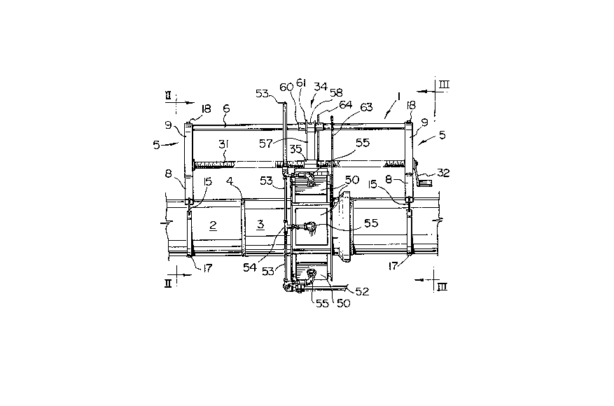
Figure 1 is a side elevation view of a section of
pipe and sleeve with an apparatus in accordance with -the
present invention mounted thereon;
Figures 2 and 3 are cross sections taken generally
along ]ines II-II and III-III, respectively of Fig. 1;
Figure 4 is an isometric view of one end of a main
frame used in the apparatus of Figs. l to 3;
Figure 5 is an exploded, isometric view of a
portion of a heater frame and carriage used in the apparatus
of Figs. :1 t.o 3;
Figure 6 is a perspective view of the entire
heater frame of Fig. 5;
Figure 7 is a schematic end elevational view of
the main frarne, heater frame, and frame operating arms used
in the apparatus of Figs. l to 3; and
Figure 8 is an isometric view of one of the heater
frame operating arms of Fig. 7.
Re~erring to Figs. 1 to 3, the apparatus o the
present invention includes a main frame generally indicated
2n at 1 for mounting on a pipe 2 straddling a sleeve 3 to be
shrunk onto an adhesive coating 4 on the pipe 2, The frame
l is defined by a pair of skeletal posts generally indicated
at 5 interconnected by a -tubular guide bar 6. ~ach post 5
~Fig. 4) is defined by strips of metal forming a generally
rectangular lower portion 8 and a generally triangular upper
:: .. . .
:; . .
. , .

Z~)0~221.
.
portion ~. The base 10 of the lower portion ~ncludes a
...
concavo-convex centre 11 for seatln0 on the plpe 1, ancl a
pair of upwardly inclined wings 12 at the ends thereof with ~-
, .~,
holes 14 ~one shown - Fig. 4) for re~eiving hook~ 15 (Figs.
i,
1 to 3) which connect the post~5~-to a re-taining ~trap 17.
bolt 18 extencls~through an~opening~20;(Fig. 4~ in the top 21
~ : : ~ :: : : -
of the upper portion 9~of ea~h~post 5~and through one encl of
-the guide bar 6 and a~nut~23 for~holding -the bar 6 in the
~; post 5.
10 ~ The -top~25 of -the~lowe~r~partion 8~and the bottom
ends~6 of the upper~portion 9~of~each post;5 carry a pillow
block bearing 28 (Flga.~2~and 3). Por such purp~ose, aligned
holes 29 are provide~d;~ln~the~ends~;26 of~ th~ upper portlon 9
and~;~in the top~25~of~the~lowe~po~r~lan~8~oE~ the~post 5~ A
15~ drive sclew 31~extends~between~and~ s~rotata;bly~ounted in
the~beaxings 23.~The~screw 31 is rotated;by a handle 32
mounted~on one~énd~thereof. Of couLse~ the handle 32 can ~e
replaced by a~rever~slb1;e,;varL~able speed motor ~not shown).
With~reference to~Figs.~5 and 6, the screw 31
~ carrles a carrla~g~e~generally~ ndlcated~at~34.~The carriage
34 includes ~n internally thxeaded, hexagona~l sleeve 35 with
,
a bar 36 suspendecl from the bottom thereof. The bar 36
carries a pa:ir of s~ort sleeve~s 38, which~combine with a pin
39 to support a~hlnge~40. ~The~hlnge~40 lnclude~s a palr of
~5 ~ plates 42 extending~downwardly~be~ween~longitudinally
:
:~: :: : :: ~: : ;
: ~ ;

-` ;20042Z1
:.
: ::
e~tending top bars 43 of the sides 45 oE a bifurccated heater
frame. Each sicle 45 includes~the top bars 43, ~ottom bars
46 and generally C-shaped end plates 4~. When the frame
sides 45 are in the cloaed position (Flgs. 2, 3 and 6), the
end plates 48 define hexagons around the pipe 2. Holes 49
are provided in the plates 48 fQr receiving bolts ~not ,'-
shown), which connec-t rectanqular~hea-ters S0 to the frame
~ : .
45. ~ ~ ;
The heaters~50;are plefer~ably catalltic heaters oL
~10 the~type avai~able~from~Cls-an Sales Western I.td. (Cata
Dyne - trade name)~buk may~also~be in~rared~heaters of the
type available~ ~rom C.H.C.~ Incorporated [Model '~-6-6 (FX)
N].~ Other su~table heaters are;avallahle from Farris ,~,
In~ustries Canada (Model';~6X~6) a~nd~Tel,edyne Merla (Model 855-
lS ~ 013~-AA0-00).;~Fuel~ls~fed~to~the~he~a~ters vi~a an inle-t pipe
52,~tubing 53,- T-jolnts~'54 and lnlet couplings 55.
Rotation o:E the frame sides 45 on the screw 31 is ',
prevented by a~post~57 integral wi~th and extendlng upwardly
from the sleeve 35. A U-shapecl top end or yoke 58 on the
~20 ~ ~post 57 embraces a~sleeve 60, which lS slidably mounted on
the~guide bar ~ pair~ of r~ings 61 are provided on the
sleeve 60 for ensuring that the lat-ter moves with the '~
carriage 34. ~ ~ ~
The heater~rame sldes~45 are rotated between open , `'
(Fig. 7~ and clo~sed (Figs~. l to 3 and 6) p~sitions by means
'
~ 5 ~ ~ :
:~

zoo~2~
of a pair of arms 63 and 64 ~Fig, 8). The bot-tom ends of
the arms 63 and 64 are pivotally conneoted to the sides 45
by pins 66, so that vertical movement of the arms 63 and 64 ~'
is accompanied by rotation of the sides 45 around -the :~
longitudinal axes of the pin 39 (Fig. 5). Each arm 63 and
64 contains a pai~ of semlcircular yrboves 6S and 69. ~When
the sides 45 are in the open position (Fi~. 7), the ~rooves ~
68 rest on the guidebar 6~. ~When the heater is in the closed~ ;
position ~Figs. 1 to~3~ thè~ groove 69 on the bar 63 rests on
the guide bar 6, dnd the groove 69 on the s~tepped bar 64
rests on the sleeve 60 ~Fig. 1)~. The bars 63 and 64 serve
to releasably retain the heater frame sides 45 in the open
or closed posltl;on. ~
In a shrink~wrapping operation, the main frame l -"
.
~arrying the hèater frame 45~and the heaters 50 in the open
posltlon is mo~nted~on~thé~ p1pe. ~The sides 45 of the heater
rame~are moved to~the closed position so that the heaters
::
50 define in this particular configuration a hexagonal
s1eeve, The handle 32 and~consequently -the screw 31 are
rotated to move the heaters 50 ~ack and forth over the pipe
2 to~preheat the~ atte~ he~sleeve ~3 is moved in-to
position on the preheated pipe 2 by sliding the sleeve into
position or by~wrapping the sleeve around the pipe,
; depending on wh.ich type o~f sleeve lS being appllec1, The
hea-ters 50 are~then moved at a cons-tant speed along the
:':: ~ : :
~: .
- 6 -
:

`` 2(10~ZZ~ ~
sleeve 3 from either end~thereof. The sleeve 3 will start
to shrink as it erlters the heater frame, and should be ' -
completely shrunk by the center of the heatiny area.
The speed oE travel of the heaters 50 can be
adjusted to suit the particular sleeve 3 and o~her
parameters. Experience has proven that shrink sleeves ~an
be applied to 2 to 8!~ plpe at a rate of six irlches per `;
minute. Followin~ application, the sleeve manufa~turer s
recommendations are used ;to remove~air bubbles or to press
- ~10 the sleeve around welds or~overlaps~
~ ~ : ~: : -, .
: ~ ~ ,::
: : : ''
:
:: :
:: :
-~7 -
::: :::
.

Representative Drawing
A single figure which represents the drawing illustrating the invention.
Administrative Status

2024-08-01:As part of the Next Generation Patents (NGP) transition, the Canadian Patents Database (CPD) now contains a more detailed Event History, which replicates the Event Log of our new back-office solution.

Please note that "Inactive:" events refers to events no longer in use in our new back-office solution.

For a clearer understanding of the status of the application/patent presented on this page, the site Disclaimer , as well as the definitions for Patent , Event History , Maintenance Fee  and Payment History  should be consulted.

Event History

Description Date
Inactive: IPC deactivated 2019-01-19
Inactive: First IPC assigned 2018-06-20
Inactive: IPC assigned 2018-06-20
Inactive: IPC expired 2018-01-01
Inactive: Expired (new Act pat) 2009-11-29
Inactive: IPC from MCD 2006-03-11
Letter Sent 2002-11-26
Letter Sent 2002-06-20
Inactive: Office letter 2002-03-05
Letter Sent 2002-03-05
Inactive: Entity size changed 2002-02-14
Inactive: Late MF processed 2002-01-31
Inactive: Multiple transfers 2002-01-28
Letter Sent 2001-11-29
Grant by Issuance 1994-11-08
All Requirements for Examination Determined Compliant 1992-01-20
Request for Examination Requirements Determined Compliant 1992-01-20
Application Published (Open to Public Inspection) 1991-05-29

Abandonment History

There is no abandonment history.

Maintenance Fee

The last payment was received on 

Note : If the full payment has not been received on or before the date indicated, a further fee may be required which may be one of the following

  • the reinstatement fee;
  • the late payment fee; or
  • additional fee to reverse deemed expiry.

Please refer to the CIPO Patent Fees web page to see all current fee amounts.

Fee History

Fee Type Anniversary Year Due Date Paid Date
MF (patent, 8th anniv.) - small 1997-12-01 1997-10-02
MF (patent, 9th anniv.) - small 1998-11-30 1998-02-04
MF (patent, 10th anniv.) - small 1999-11-29 1999-01-08
MF (patent, 11th anniv.) - small 2000-11-29 2000-02-18
Reversal of deemed expiry 2001-11-29 2001-03-27
MF (patent, 12th anniv.) - standard 2001-11-29 2001-03-27
Registration of a document 2002-01-28
MF (patent, 13th anniv.) - standard 2002-11-29 2002-06-11
MF (patent, 14th anniv.) - standard 2003-12-01 2002-11-19
MF (patent, 15th anniv.) - standard 2004-11-29 2004-11-15
MF (patent, 16th anniv.) - standard 2005-11-29 2005-11-15
MF (patent, 17th anniv.) - standard 2006-11-29 2006-11-24
MF (patent, 18th anniv.) - standard 2007-11-29 2007-03-19
MF (patent, 19th anniv.) - standard 2008-12-01 2008-09-29
MF (application, 2nd anniv.) - small 02 1991-11-29
Owners on Record

Note: Records showing the ownership history in alphabetical order.

Current Owners on Record
CCI THERMAL TECHNOLOGIES INC.
Past Owners on Record
ALAN CAMERON KIRBY
Past Owners that do not appear in the "Owners on Record" listing will appear in other documentation within the application.
Documents

To view selected files, please enter reCAPTCHA code :


To view images, click a link in the Document Description column. To download the documents, select one or more checkboxes in the first column and then click the "Download Selected in PDF format (Zip Archive)" or the "Download Selected as Single PDF" button.

List of published and non-published patent-specific documents on the CPD .

If you have any difficulty accessing content, you can call the Client Service Centre at 1-866-997-1936 or send them an e-mail at CIPO Client Service Centre.


Document
Description 
Date
(yyyy-mm-dd) 
Number of pages   Size of Image (KB) 
Drawings 1997-09-19 4 152
Claims 1997-09-19 2 103
Abstract 1997-09-19 1 69
Descriptions 1997-09-19 7 396
Cover Page 1994-11-08 1 15
Representative drawing 1999-07-15 1 31
Maintenance Fee Notice 2002-02-14 1 179
Late Payment Acknowledgement 2002-02-18 1 172
Maintenance Fee Notice 2002-02-14 1 179
Correspondence 2002-11-26 1 16
Fees 2002-11-19 1 41
Fees 2003-10-06 1 31
Fees 1998-02-04 1 37
Fees 2002-01-31 1 37
Correspondence 2002-03-05 1 12
Fees 2001-03-27 1 30
Fees 1999-01-08 1 31
Correspondence 2002-06-20 1 7
Fees 2002-06-11 1 39
Fees 1997-10-02 1 36
Fees 2000-02-18 1 31
Fees 2004-11-15 1 31
Fees 2005-11-15 1 34
Fees 2006-11-24 1 28
Fees 2007-03-19 1 28
Fees 2008-09-29 1 30
Fees 1996-08-26 1 34
Fees 1995-05-11 1 45
Fees 1993-06-22 1 38
Fees 1994-10-28 1 40
Fees 1992-11-13 1 41
Fees 1992-01-07 2 77
Prosecution correspondence 1992-01-20 1 30
Examiner Requisition 1993-06-01 1 63
Prosecution correspondence 1993-08-16 2 55
Prosecution correspondence 1994-08-24 2 60
Prosecution correspondence 1992-11-30 2 64
PCT Correspondence 1992-11-06 1 29
PCT Correspondence 1992-09-18 2 60
Courtesy - Office Letter 1992-08-17 1 13
Courtesy - Office Letter 1992-03-10 1 41
Courtesy - Office Letter 1992-11-16 1 135
Courtesy - Office Letter 1992-11-16 1 58