Language selection

Search

Patent 2004683 Summary

Third-party information liability

Some of the information on this Web page has been provided by external sources. The Government of Canada is not responsible for the accuracy, reliability or currency of the information supplied by external sources. Users wishing to rely upon this information should consult directly with the source of the information. Content provided by external sources is not subject to official languages, privacy and accessibility requirements.

Claims and Abstract availability

Any discrepancies in the text and image of the Claims and Abstract are due to differing posting times. Text of the Claims and Abstract are posted:

  • At the time the application is open to public inspection;
  • At the time of issue of the patent (grant).
(12) Patent: (11) CA 2004683
(54) English Title: MULTI-GATE MOLDING HEATER ASSEMBLY
(54) French Title: ELEMENTS CHAUFFANTS POUR MOULE D'INJECTION MULTICANAL
Status: Expired and beyond the Period of Reversal
Bibliographic Data
(51) International Patent Classification (IPC):
  • B29C 45/74 (2006.01)
  • B29C 45/27 (2006.01)
  • B29C 45/30 (2006.01)
(72) Inventors :
  • TRAKAS, PANOS (United States of America)
(73) Owners :
  • PANOS TRAKAS
(71) Applicants :
(74) Agent: OSLER, HOSKIN & HARCOURT LLP
(74) Associate agent:
(45) Issued: 1994-04-05
(22) Filed Date: 1989-12-06
(41) Open to Public Inspection: 1990-09-01
Examination requested: 1989-12-06
Availability of licence: N/A
Dedicated to the Public: N/A
(25) Language of filing: English

Patent Cooperation Treaty (PCT): No

(30) Application Priority Data:
Application No. Country/Territory Date
317,614 (United States of America) 1989-03-01

Abstracts

English Abstract


MULTI-GATE HEATER ASSEMBLY
ABSTRACT OF THE DISCLOSURE
An injection molding heater assembly for use in
multi-gate injection molding includes an elongate heating
member extending within a mold bore in heating communication
with the mold bore mold gates. The heating member has an
elongate body portion extending between an inlet portion and an
outlet portion. A melt injection passage extends through the
inlet portion to convey melt along the body portion to an
enlarged portion having a nozzle face. Extending down from the
nozzle face are a series of members which include gate tips at
their lower ends. Radial channels present in the gate tips
serve as extensions to the mold bore mold gates. The gate tips
are peripherally spaced apart around the nozzle face and define
a recess between the gate tips, the nozzle face and the mold
bore for initially injected melt to accumulate in and solidify
to form a melt plug. The melt plug serves to insulate the
subsequently injected melt from the mold bore and maintain the
injected melt in a third condition.


Claims

Note: Claims are shown in the official language in which they were submitted.

What I Claim Is:
1. An improved injection molding heater assembly for
heating melt which is injected into a mold bore having a
plurality of mold gates leading to a plurality of mold
cavities, the heater assembly comprising:
an elongate heating member providing a heated passage
for the flow of melt to the multiple mold gates, the heating
member having a body portion extending between an inlet end and
a discharge end of the heating member, the body portion being
dimensioned to extend within the mold bore and,
the discharge end of the heating member including an
enlarged portion positioned in melt flow communication with the
multiple mold gates for directing the flow of melt into said
multiple mold gates, said enlarged portion including a
plurality of melt flow directing members extending from a
nozzle face disposed on said enlarged portion and having gate
tips thereon, the gate tips corresponding in number to the
number of multiple mold gates in said mold bore, said melt flow
directing members being peripherally disposed on said enlarged
portion of the discharge end of said heating member and
extending radially downwardly and outwardly therefrom, each of
said gate tips having an outer wall which is dimensioned to be
closely spaced to said mold gates when said heater assembly is
inserted into aid mold bore, each of said gate tips further
including an arcuate inner wall extending from said enlarged
portion to define a recess between said gate tips and said mold
bore for the accumulation of injected melt therein, whereby the
accumulated melt solidifies and forms an insulating layer
between the discharge end of said heating member and said mold
bore to minimize heat loss from the injected melt to said mold
bore.
-11-

2. The multi-gate heater assembly of claim 1,
wherein said elongate heated member includes a heated torpedo
and the heated member inlet includes a annular collar radially
spaced apart from said torpedo, the annular collar defining at
least one heated melt passage extending along the torpedo body
portion between the annular collar and said torpedo, said
torpedo further including means for positioning said torpedo
within said mold bore, said positioning means extending
radially outwardly from said torpedo between said inlet end and
said outlet end said positioning means further abutting said
mold bore.
3. The multi-gate heater assembly of claim 2,
wherein said torpedo positioning means includes a plurality of
fins peripherally disposed on said torpedo, the outer ends of
said fins contacting the internal surface of said mold bore
when said torpedo is inserted therein.
4. The multi-gate heater assembly of claim 1,
wherein said elongate heated member includes a sprue bushing
having a central melt passage extending through the body
portion of said bushing between said inlet and said outlet and
further opening onto said nozzle face, said bushing including
means for positioning said bushing within said mold bore, said
positioning means extending radially outwardly from said
bushing body portion between said inlet and said outlet.
5. The multi-gate heater assembly of claim 4,
wherein said positioning means further includes means for
sealing said mold bore to prevent the backflow of melt injected
-12-

into said mold bore, said sealing means including a skirt
radially extending from said bushing body portion to contact
the interior surface of said mold bore in a sealing
relationship.
6. An injection molding heater assembly for heating
melt injected into an injection molding mold block mold bore,
wherein the mold bore has multiple mold cavities and multiple
mold gates leading to the mold cavities, the heater assembly
having a melt inlet end and a melt outlet end, comprising an
elongate heater member adapted to centrally extend into said
mold bore in heating communication with said mold bore, said
elongate heater member including a torpedo, said melt inlet end
of said heater member having a longitudinal melt transfer
passage extending through said melt inlet end and providing a
flow passageway for heated melt through said melt inlet end
along the body of said torpedo, said torpedo body including an
enlarged portion thereon at said melt outlet end, said enlarged
portion including a lower gate tip portion having a plurality
of gate tips corresponding in number to the number of mold
gates of said mold bore, each of said gate tips extending
downwardly from said torpedo enlarged portion and outwardly
from said torpedo body to a position adjacent a mold cavity
gate, each of said gate tips having an outer wall which is
complementary in configuration to said mold bore and an arcuate
inner wall, said gate tips being spaced apart and peripherally
disposed on said torpedo enlarged portion so as to define a
recess beneath said torpedo enlarged portion and between said
torpedo enlarged portion said mold bore and said gate tips,
each of said gate tips having a lower face which includes a
-13-

channel extending radially accross at least a portion of the
lower face, the channel being aligned with said mold gates when
said torpedo is inserted into said mold bore, said recess
providing an area in said mold bore for injected melt to
accumulate in and to solidify in so as to form a melt layer
between said gate tips and said mold bore which insulates
subsequently injected melt from said mold bore and minimizes
heat loss from the injected melt to said mold bore.
7. The injection molding heater assembly of claim 6,
wherein said torpedo further includes radially extending fins
spaced apart on said torpedo, said fins centrally positioning
said torpedo in said mold bore and further positioning said
gate tips in alignment with said mold gates.
8. In an injection molding heater assembly for
heating injection melt supplied from an injection molding
machine to a mold block having multiple mold cavities, the mold
block including a mold bore extending therein which provides a
passage for melt from said molding machine to the multiple mold
cavities, said mold block including a plurality of gates
corresponding to the number of said mold cavities which define
mold passages for communicating the flow of melt from said mold
bore to said mold cavities, the improvement comprising, an
elongate heated bushing member having a bushing melt inlet end
and a bushing melt outlet end, the bushing member further
having a melt transfer passage generally centrally disposed
therein and extending axially through said bushing, the bushing
melt outlet end terminating in a bushing enlarged end portion
having a substantially flat nozzle face disposed thereon and
-14-

gate direction means including a plurality of gate tips
corresponding in number to the number of mold cavity gates in
said mold bore, said gate tips being peripherally disposed on
said bushing nozzle face and downwardly extending therefrom and
outwardly extending from a bushing body portion to points
adjacent said mold gates, said gate tips having outer surfaces
which are generally complementary in configuration to said mold
bore and further having arcuate inner surfaces, said gate tips
further including a radial channel extending across a gate tip
lower surface, said gate tips defining a recess between
themselves and said mold bore when said bushing is inserted
into said mold bore, said recess being positioned from said
mold bore to provide an accumulation area for injected melt to
accumulate in and to solidify in so as to form a melt layer
between said gate tips and said mold bore which insulates
subsequently injected melt from said mold bore and minimizes
heat loss from the injected melt to said mold bore, said
bushing member further including means for positioning said
bushing within said mold well including a skirt extending
radially from said bushing and disposed on said bushing between
said melt inlet and outlet ends.
9. The injection molding heater assembly of claim 8,
wherein said skirt means further includes an annular seal
member for sealing the flow of melt in said mold bore.
-15-

Description

Note: Descriptions are shown in the official language in which they were submitted.


PATENT
Case 871116
NUL~I-GATE MOLDING HEATER ASSEMBLY
Panos Trakas
Background and SummarY of the Invention
The present invention relates generally to
injection molding systems using a heated nozzle disposed
in a mold bore to inject melt into multiple mold cavities
having multiple mold gates opening from the mold bore into
the mold cavities, and more particularly to an improved
heater assembly used in multi-cavity injection mold
gating.
Injection molding is widely used for the
manufacture of a variety of items, some of which have thin
and delicate cross sections. These items can be molded in
large quantities by using a single heated nozzle that
extends into a single mold bore which feeds a number of
mold cavities. These mold cavities typically have gates
which extend through the mold block between the mold bore
and the mold cavity, forming a melt flowpath to convey the
injected melt from the bore to the mold cavities. These
~ gates are very small in cross-section and therefore it is
- desirable to provide a sufficient and constant application
of heat to the melt flow which is directed toward each
mold gate to ensure that the melt remains fluid while
passing through the gates into the mold cavities.
~, .

One previous construction of a heated multiple
gate nozzle which directs the melt to multiple mold gates
is shown in Canadian Patent No. 976,314, in which a
multi-gate heater is disclosed having an intricately
milled nozzle face with a series of convex openings formed
therein. Another construction such as that shown in U.S.
Patent No. 4,094,447 relies in part on a specific
configuration of the mold bore whi~h includes a raised
portion of the bore which is generally complementary to
the heater nozzle face to fill much of the open area in
the bore to cut down on the amount of heat transferred to
the mold block during operation. Such approaches require
costly machining of both the heater ends and mold block
mold bore.
The present invention is directed to an
injection molding multi-gate heater assembly construction
; which is less costly to manufacture in that it does not
require extensive machining of the heater nozzle face or
of the mold bore, and which has imporved heat transfer and
reduced heat loss capabilities.
In a multi-gate molding heater assembly
constructed in accordance with the present invention, an
elongate heated member having opposing inlet and outlet
ends i8 adapted to fit in a mold bore. The heater has a
melt injection passage extending through its inlet which
directs fluid melt along a body portion of the heated
member to a lower member enlarged portion having a nozzle
face thereon heated member. The nozzle face has a number
of gate tips disposed around its periphery which tips
extend downwardly from the nozzle face and away from the
.
~.

heated member body portion to a position in registration with
multiple mold gates located in the mold bore. A recess i8
formed between the gate tips and the mold bore and acts
as a melt accumulation area for the initially injected
melt to solidify in such that it insulates the subsequently
injected melt from the cooler temperatures of the mold
block surrounding further the mold bore.
Accordingly, it is a general object of the
present invention to provide an improved heater assembly
for use in injection molding systems having multiple
gates.
Another object o~ the present invention is to
provide a heated sprue bushing having a central melt
injection passage which terminates in a bushing nozzle
face having multiple gate tips peripherally disposed
thereon which direct the melt to the mold bore gates.
It is another object of the present invention
to provide a heated torpedo for insertion into a mold bore
having a plurality of mold gates defining melt pa sages to
mold cavities disposed in the mold bore wherein the
torpedo has multiple gate extension tips disposed thereon
in alignment with the mold bore gates.
It is still yet another object of the present
invention to provide an improved heater assembly adapted
to fit within a mold bore having multiple gates leading to
multiple mold cavities, the heater assembly having
multiple gate tips peripherally disposed on a heater
nozzle face which engage the mold gates, the gate tips
defining a recess between the nozzle face and the mold

(14~i~`)3
bore for the aecumulation of melt therebetween for
insulating the heated melt from the mold bore.
These and other objects, features and advantages
of the present invention will be clearly understood
through a consideration of the following detailed
description.
Brief DescriPtion of the Drawings
In the course of this description, reference
will be frequently made to the attached drawings in which:
FIG. 1 is a perspective view of one embodiment
of a multi-gate heater assembly incorporating the
principles of the present invention;
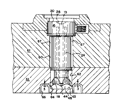
FIG. 2 is an elevational view of the heater
assembly of FIG. 1 in place within a bore in a mold block;
FIG. 3 is a bottom plan view of the heater of
FIG. 1 which is partially in section taken along lines 3-3
of FIG. 2;
FIG. 4 is an enlarged view of the nozzle face
end of the heater of FIG. 1 in place in the mold bore;
FIG. 5 is an elevational view of a
second embodiment of a multi-gate heater assembly
: incorporating the principles of the present invention;
FIG. 6 is a plan view of the heater assembly of
FIG. 5 taken along lines 6-6, and
FIG. 7 is an elevational view of a pair of the
heater assemblies shown in FIG. 5 in place within a mold
block bore.
-4-
... .
... .

t~
Description oi the Preferred Embodiments
A first embodiment of heater assembly 10 which
incorporates the principles of the preeent invention i8
shown in FIGS. 1-4. The heater assembly 10 comprises an
elongate, generally cylindrial member 12, shown as a sprue
bushing 14, having an inlet portion 16 and an outlet
portion 18 with a bushing body portion 34 extending
therebetween. A melt injection passage 13 extends axially
through the bushing to form a passage to convey molten,
fluid melt through the inlet end 16 along the interior of
bushing body portion 34 to the nozzle face 37 of the
bushing 14. The bushing inlet portion 16 may be
integrally formed with the bushing body 34 or it may be
separately formed and joined together such as by welding.
The body portion 34 preferably includes an internal
electrical heater element 24 which surrounds the melt
injection passage 13 and supplies sufficient heat to the
entire heater assembly 10 to maintain the melt passing
through the injection passage 13 and into the mold bore 60
in a molten state.
The bushing body 34 and inlet portion 16 are
generally cylindrical, with each of them respectively
having different uniform outer diameters with the outer
diameter of the body 34 being generally reduced with
respect to that of the inlet portion 16. An enlarged
inlet cap portion 20 is shown to include a nozzle seat 28
at melt passage inlet 30 to receive an injection molding
machine or manifold nozzle (not shown). The bushing body
34 extends between the inlet portion 16 and a lower
: .

bushing enlarged portion 36. The bushing enlarged portion
36 includes a substantially flat surface 38 having a
bushing nozzle face 37 in surrounding relation to the
outlet end of injection passage 13.
SurrouDding the bushing lower face 38 are mean~
for directing the melt flow into the mold cavity gates 64,
shown as members 40 which exten~ a predetermined distance
down from the nozzle face 37 and a predetermined distance
out from the bushing body 34. The four members 40 are all
generally of equal size and each includes an outer surface
49 which is generally complementary in its surface
configuration to mold bore wall 62 and an inner, curved
surface 47 which extends from the bushing nozzle face 37
to a gate tip 42 at the member lower end 43. The gate tip
42 includes a gate extension or channel 44 which extends
radially across the gate tip end 43.
The members 40 extend downward from the nozzle
face 37 and away from the bushing body 34 a predetermined
distance so that the gate tips 42 are very closely spaced
to the mold bore wall 62 ~FIG. 4) and the gate tip
channels 44 are aligned with the mold gates 64 leading to
the mold cavities 66 when the heater 10 is inserted into
the mold bore 60. In accordance with one aspect of the
present invention and as i8 shown in FIGS. 2 and 4, the
gate tips 42 create a recess 46 in the mold bore 60. The
recess 46 is located between the inner curved surfaces 47
of gate tips 42, the bushing nozzle face 37 and the mold
bore bottom 63.
In operation, the injected melt flows through
the central injection passage into the mold bore 60 and

~ it~
fills the lower portion of the mold bore 60. The
initially injected melt solidifies when it contacts the
cooler mold bore walls 62 and forms a melt plug 48 which
substantially fills the recess 46 and the annular space 56
above the gate tips 42 to surround the bushing enlarged
portion 36. The gate tips 42 are heated by the bushing
internal heater 24 so that the melt in communication with
the nozzle face 37 and gate tips 42 remains fluid and
creates a melt flow path 50 between the bushing nozzle
face 37, the gate tips 42 and the mold block mold gates
64. This melt flow path 50 functions as a melt passage
opening between the melt plug 48 and the heater (FIG~ 4).
Melt plug 48 serves as a thermal layer between
the bushing nozzle face 37 and the surrounding mold block
61 which insulates the subsequent melt flow from the
cooler mold bore and thereby maintains an even heat
. distribution from the heater 10 to the gate tips 42. In
this manner, subsequent melt is maintained in a fluid
state as it passes through the heated flowpath 50 into the
; 20 mold block gates 64 and heat loss from the fluid melt to
: the mold bore is thereby minimized.
As shown, bushing 14 further includes means for
sealing the mold bore 60 against melt flow in the form of
a skirt or annular flange 52 located on the bushing body
34 between the bushing inlet 16 and the enlarged portion
36. Skirt 52 extends a predetermined distance radially
outwardly from the bushing body 34 such that it contacts
the mold bore wall 62 and provides a seal 54 between the
lower area of the mold bore and the mold bore opening 67.
In this regard, the outer diameter of the skirt 52 is
; . . .

~ ti~S
slightly greater than the overall outer diameter of the
bushing enlarged portion 36. In operation, melt ifi force~
through the spaces between the gate tip members 40 back up
the mold bore 60 due to the injection presRure into the
annular space 56 until it contacts the skirt seal 52,
which prevents further back flow of melt within the mold
bore. Melt occupying this annular space 56 solidifies and
provides an additional layer of insulation between the
bushing 14 and the mold bore 60 to further minimize heat
loss from the bushing to the mold block 61. Skirt 52 also
maintains the bushing 14 in a central position in the mold
bore and positions the gate tip members 40 a
predetermined selected distance away from the mold bore
wall 62.
A second embodiment of a heater assembly 70 of
the present invention is illustrated in FIGS. 5-7 which
includes an elongate, generally cylindrical heater member
72 in the form of a torpedo 75 having an inlet end portion
74 and a discharge end portion 76. Torpedo inlet portion
74 includes an annular collar 78 which overlies the top of
the torpedo 75 and is shown as radially spaced apart from
the torpedo body 79 by ribs 80. A pluriality of radially
extending ribs 80 define a series of melt injection
pas~ages 83 located between the interior of inlet collar
78 and the torpedo body 75 which direct the flow of
injected melt along the torpedo body 79 to the outlet
torpedo end face 84. Inlet collar 78 preferably is
adapted to receive an electrical cable 81 which contains
the necessary electrical wiring to supply power to an
internal heater element 73 centrally disposed within the
--8--

torpedo 75 for heating the melt injected into the mold
bore 60.
In a construction similar to that of the ~irst
embodiment, the heater assembly torpedo body 79 has a
generally enlarged portion 82 at its lower end which
includes a generally flat torpedo end face 84.
Peripherally disposed around the torpedo end face 84 are a
series of members 86 which extend a predetermined distance
down from the torpedo end face 84 and extend a
predetermined distance out from the torpedo body 79. Each
member 86 has an outer wall 85, which has a surface
configuration generally complementary to the configuration
of the mold bore wall 62. Each of members 80 also
includes a curved inner wall 87 which radially extends
downwardly and outwardly from the torpedo end face 84
terminating in a lower surface 89 that defines a gate tip
or extension 88. The gate tips 88 each include a lower
face 90 having a radial channel 92 cut therein extending
radially across the gate tip lower face 90. Members 86
are located on the torpedo lower enlarged portion 82 such
that the gate tips 88 are closely spaced to the mold bore
wall 62 with the gate tip radial channels 92 being in
alignment with the mold bore gates 64. In accordance with
one aEpect of this invention, the downward spacing of the
ends of gate tips 88 from the torpedo end face 84
define a recess 95. Initially injected melt accumulates
and solidifies in the recess 95 to provide a melt plug 94
which insulates subsequently injected melt from the cooler
mold bore walls 62.
_g_
.. .. .
.~,. . .

In use, the melt i8 injected into the torpedo
inlet 74 and passes through the injection passages 83
along the torpedo body 79 to the nozzle outlet face 84
where it is directed into the mold gates 64 by the gate
tips 88. The initial melt will solidify in the lower
portion of the mold bore 60, namely, in the recess 95 and
the annular space 93 surrounding the torpedo body 79 where
it contacts the cooler mold bore wall 62, but will remain
fluid near the torpedo body 7g and the nozzle face 84 so
as to define a melt flow path 99 for subsequent melt to
pass through.
Means for positioning the torpedo within the
mold block bore 60 are located on the torpedo body 79
generally midway between the torpedo inlet 74 and the
lower enlarged portion 82, preferably near the torpedo
lower enlarged portion 82. These positioning means are
shown in FIGS 5-7 as radially extending fins 96. The fins
96 extend a selected distance out from the torpedo body 79
so that they contact the mold bore wall 60 and properly
position the gate tips 88 with respect to the mold gates
64.
It will be understood that the embodiments of
the present invention which have been described are merely
illustrative of a few applications of the principles of
the invention. Numerous modifications may be made by
those skilled in the art without departing from the true
spirit and scope of the invention.
--10--
,.~. . .
~. .

Representative Drawing
A single figure which represents the drawing illustrating the invention.
Administrative Status

2024-08-01:As part of the Next Generation Patents (NGP) transition, the Canadian Patents Database (CPD) now contains a more detailed Event History, which replicates the Event Log of our new back-office solution.

Please note that "Inactive:" events refers to events no longer in use in our new back-office solution.

For a clearer understanding of the status of the application/patent presented on this page, the site Disclaimer , as well as the definitions for Patent , Event History , Maintenance Fee  and Payment History  should be consulted.

Event History

Description Date
Time Limit for Reversal Expired 2007-12-06
Letter Sent 2006-12-06
Inactive: IPC from MCD 2006-03-11
Grant by Issuance 1994-04-05
Application Published (Open to Public Inspection) 1990-09-01
All Requirements for Examination Determined Compliant 1989-12-06
Request for Examination Requirements Determined Compliant 1989-12-06

Abandonment History

There is no abandonment history.

Fee History

Fee Type Anniversary Year Due Date Paid Date
MF (patent, 8th anniv.) - small 1997-12-08 1997-11-04
MF (patent, 9th anniv.) - small 1998-12-07 1998-11-03
MF (patent, 10th anniv.) - small 1999-12-06 1999-11-04
MF (patent, 11th anniv.) - small 2000-12-06 2000-11-03
MF (patent, 12th anniv.) - small 2001-12-06 2001-11-02
MF (patent, 13th anniv.) - small 2002-12-06 2002-11-04
MF (patent, 14th anniv.) - small 2003-12-08 2003-11-05
MF (patent, 15th anniv.) - small 2004-12-06 2004-12-06
MF (patent, 16th anniv.) - small 2005-12-06 2005-11-14
2005-11-14
Owners on Record

Note: Records showing the ownership history in alphabetical order.

Current Owners on Record
PANOS TRAKAS
Past Owners on Record
None
Past Owners that do not appear in the "Owners on Record" listing will appear in other documentation within the application.
Documents

To view selected files, please enter reCAPTCHA code :


To view images, click a link in the Document Description column. To download the documents, select one or more checkboxes in the first column and then click the "Download Selected in PDF format (Zip Archive)" or the "Download Selected as Single PDF" button.

List of published and non-published patent-specific documents on the CPD .

If you have any difficulty accessing content, you can call the Client Service Centre at 1-866-997-1936 or send them an e-mail at CIPO Client Service Centre.


Document
Description 
Date
(yyyy-mm-dd) 
Number of pages   Size of Image (KB) 
Claims 1997-09-19 5 181
Abstract 1997-09-19 1 21
Drawings 1997-09-19 3 103
Cover Page 1997-09-19 1 11
Representative Drawing 2000-02-29 1 23
Descriptions 1997-09-19 10 333
Maintenance Fee Notice 2007-01-17 1 171
Fees 2004-12-06 1 36
Fees 1996-11-14 1 64
Fees 1993-09-22 1 31
Fees 1992-09-29 1 27
Fees 1991-12-04 1 28
Fees 1995-11-14 1 87
Fees 1994-09-21 1 59
Fees 1992-10-28 1 28
Courtesy - Office Letter 1991-12-02 1 33
PCT Correspondence 1993-12-21 1 22
PCT Correspondence 1991-10-23 2 55