Language selection

Search

Patent 2004786 Summary

Third-party information liability

Some of the information on this Web page has been provided by external sources. The Government of Canada is not responsible for the accuracy, reliability or currency of the information supplied by external sources. Users wishing to rely upon this information should consult directly with the source of the information. Content provided by external sources is not subject to official languages, privacy and accessibility requirements.

Claims and Abstract availability

Any discrepancies in the text and image of the Claims and Abstract are due to differing posting times. Text of the Claims and Abstract are posted:

  • At the time the application is open to public inspection;
  • At the time of issue of the patent (grant).
(12) Patent: (11) CA 2004786
(54) English Title: LEVITATOR
(54) French Title: SYSTEME DE LEVITATION
Status: Term Expired - Post Grant Beyond Limit
Bibliographic Data
(51) International Patent Classification (IPC):
  • G05D 03/12 (2006.01)
  • B64G 01/22 (2006.01)
(72) Inventors :
  • YODA, SHINICHI (Japan)
  • ITOGA, KENJI (Japan)
  • OKUDA, SOUICHIRO (Japan)
  • IKEGAMI, KAZUNORI (Japan)
(73) Owners :
  • NATIONAL SPACE DEVELOPMENT AGENCY OF JAPAN
(71) Applicants :
  • NATIONAL SPACE DEVELOPMENT AGENCY OF JAPAN (Japan)
(74) Agent: RICHES, MCKENZIE & HERBERT LLP
(74) Associate agent:
(45) Issued: 1993-12-21
(22) Filed Date: 1989-12-06
(41) Open to Public Inspection: 1990-06-07
Examination requested: 1990-07-31
Availability of licence: N/A
Dedicated to the Public: N/A
(25) Language of filing: English

Patent Cooperation Treaty (PCT): No

(30) Application Priority Data:
Application No. Country/Territory Date
23495/1989 (Japan) 1989-02-01
309673/1988 (Japan) 1988-12-07
309674/1988 (Japan) 1988-12-07
309675/1988 (Japan) 1988-12-07

Abstracts

English Abstract


LEVITATOR
ABSTRACT OF THE DISCLOSURE:
A levitator which is mounted on a space station, for
example, for use in material science experiments in space.
The levitator has a position detector for detecting the
position of a sample, a variable power supply whose output
voltage varies in accordance with the signal output from the
position detector, a pair of planar electrodes connected
to two ends, respectively, of the variable power supply
and disposed in opposing relation to each other, and a ring
electrode disposed so as to surround each of the planar
electrodes and to which is applied a higher voltage than that
applied to the corresponding planar electrode from a DC power
supply, thereby holding the sample stationary at a desired
position by means of the planar and ring electrodes. The
levitator further has a means for rotating the sample being
held stationary. Thus, it is possible to rotate the sample
in a controlled manner and hence possible to carry out an
experiment in which the sample is uniformly heated in a
microgravity environment.


Claims

Note: Claims are shown in the official language in which they were submitted.


The embodiments of the invention in which an
exclusive property or privilege is claimed are defined as
follows:
1. A levitator having a position detector for detecting
the position of a sample, a variable power supply whose
output voltage varies in accordance with the signal output
from the position detector, a pair of planar electrodes
connected to two ends, respectively, of the variable power
supply and disposed in opposing relation to each other, and
a ring electrode disposed so as to surround each of the
planar electrodes and to which a higher voltage is applied
than that applied to the corresponding planar electrode from
a DC power supply, said planar and ring electrodes defining
means for holding the center of gravity of said sample
stationary at a desired position, wherein the improvement
comprises means separate from said sample for generating a
magnetic field about said sample for controlling rotation of
said sample about an axis through the center of gravity.
2. A levitator as set forth in claim 1 wherein said
means for generating a magnetic field comprises:
a plurality of electrodes disposed about said sample;
an alternating power supply having a frequency and
connected to said plurality of electrodes; and
wherein the sample rotates with a number of
- 14 -

revolutions equal to the product of the number of electrodes
and the frequency of the alternating power supply.
3. A levitator as set forth in claim 1 wherein said
means for generating a magnetic field comprises a permanent
magnet and means for rotating said permanent magnet.
4. A levitator as set forth in claim 1 wherein said ring
electrode comprises a plurality of electrodes; and
wherein said means for generating a magnetic field
comprises an alternating power supply connected to said
plurality of electrodes of said ring electrode.
5. A levitator having a position detector for detecting
the position of a sample, a variable power supply whose
output voltage varies in accordance with the signal output
from the position detector, a pair of planar electrodes
connected to two ends, respectively, of the variable power
supply and disposed in opposing relation to each other, and
a ring electrode disposed so as to surround each of the
planar electrodes and to which a higher voltage is applied
than that applied to the corresponding planar electrode from
a DC power supply, thereby holding the sample stationary at
a desired position by means of said planar and ring
electrodes, wherein the improvement comprises means for
rotating said sample being held stationary, wherein said
ring electrode comprises a plurality of arc-shaped
- 15 -

electrodes, and said means for rotating the sample comprises
an alternating power supply having an output means for
providing an output voltage that changes periodically, said
output means being connected to each pair of adjacent arc-
shaped electrodes of said ring electrode.
6. A levitator having a position detector for detecting
the position of a sample, a variable power supply whose
output varies in accordance with the signal output from the
position detector, a pair of planar electrodes connected to
two ends, respectively, of the variable power supply and
disposed in opposing relation to each other, and a ring
electrode disposed so as to surround each of the planar
electrodes and to which a higher voltage is applied than
that applied to the corresponding planar electrode from a DC
power supply, thereby holding the sample stationary at a
desired position by means of said planar and ring
electrodes, wherein the improvement comprises means for
generating a magnetic field for rotating said sample being
held stationary, wherein said means for rotating the sample
comprises at least one electromagnet provided at a
predetermined position outside said ring electrode to rotate
said sample by means of the magnetic field of said
electromagnet.
7. A levitator having a position detector for detecting
the position of a sample, a variable power supply whose
- 16 -

output voltage varies in accordance with the signal output
from the position detector, a pair of planar electrodes
connected to two ends, respectively, of the variable power
supply and disposed in opposing relation to each other, and
a ring electrode disposed so as to surround each of the
planar electrodes and to which a higher voltage is applied
than that applied to the corresponding planar electrode from
a DC power supply, thereby holding the sample stationary at
a desired position by means of said planar and ring
electrodes, wherein the improvement comprises means for
generating a magnetic field for rotating said sample being
held stationary, wherein said means for rotating the sample
comprises means for irradiating said sample with a plurality
of high-output beams from different directions to apply only
rotational force to said sample.
8. A levitator having a position detector for detecting
the position of a sample, a variable power supply whose
output voltage varies in accordance with the signal output
from the position detector, a pair of planar electrodes
connected to two ends, respectively, of the variable power
supply and disposed in opposing relation to each other, and
a ring electrode disposed so as to surround each of the
planar electrodes and to which a higher voltage is applied
than that applied to the corresponding planar electrode from
a DC power supply, thereby holding the sample stationary at
a desired position by means of said planar and ring
- 17 -

electrodes, wherein the improvement comprises means for
rotating said sample being held stationary, wherein said
means for rotating the sample comprises a permanent magnet
for applying a magnetic field to the space in which said
sample is located, and means for rotating said permanent
magnet.
9. A levitator for levitating and rotating a sample,
comprising:
a position detector for detecting the position of
said sample and for generating a command voltage on the
basis of said position,
a plurality of electrodes disposed in opposing
relationship, and responsive to said command voltage to
generate a magnetic field therebetween for holding the
center of gravity of said sample stationary in a desired
position, and
means separate from said sample for generating a
magnetic field about said sample for controlling rotation of
said sample about an axis through the center of gravity.
10. A levitator as set forth in claim 9 wherein said means
for generating a magnetic field comprises;
a plurality of electrodes disposed about said sample;
an alternating power supply having a frequency and
connected to said plurality of electrodes; and
wherein the sample rotates with a number of
- 18 -

revolutions equal to the product of the number of electrodes
and the frequency of the alternating power supply.
11. A levitator as set forth in claim 9 wherein said means
for generating a magnetic field comprises a permanent magnet
and means for rotating said permanent magnet.
12. A levitator as set forth in claim 9 wherein said means
for generating a magnetic field includes an alternating
power supply connected to at least some of said plurality of
electrodes, and having a frequency, whereby said sample is
rotated with a number of revolutions corresponding to the
number of electrodes connected to the alternating power
supply and the frequency of the alternating power supply.
13. A levitator as set forth in claim 9 wherein said
plurality of electrodes includes a permanent magnet; and
wherein said means for generating a magnetic field
comprises means for rotating said permanent magnet.
14. A levitator for levitating and rotating a sample,
comprising:
a position detector for detecting the position of
said sample and for generating a command voltage on the
basis of said position,
a plurality of electrodes disposed in opposing
relationship, and responsive to said command voltage to
- 19 -

generate a magnetic field therebetween, whereby said sample
is held in a desired position, and
means for irradiating said sample for rotating said
sample being held in said desired position.
15. A levitator for levitating and rotating a sample
comprising:
a position detector for detecting the position of
said sample and for generating a signal indicative of said
position,
a variable power supply having output means for
providing an output voltage that varies as a function of the
signal generated by said position detecting means,
a pair of planar electrodes disposed in opposing
relation to each other, and connected to said output means,
a pair of ring electrodes disposed so as to surround
respectively each of said planar electrodes,
means for applying a direct current voltage to each
of said ring electrodes, said direct current voltage higher
than the voltage applied to its corresponding planar
electrode by said variable power supply, whereby the center
of gravity of said sample is held stationary in a desired
position, and
means separate from said sample for generating a
magnetic field about said sample for controlling rotation of
said sample about an axis through the center of gravity.
- 20 -

16. A levitator as set forth in claim 15 wherein said
means for generating a magnetic field comprises:
a plurality of electrodes disposed about said sample;
an alternating power supply having a frequency and
connected to said plurality of electrodes; and
wherein the sample rotates with a number of
revolutions equal to the product of the number of electrodes
and the frequency of the alternating power supply.
17. A levitator as set forth in claim 15 wherein said
means for generating a magnetic field comprises a permanent
magnet and means for rotating said permanent magnet.
18. A levitator as set forth in claim 15 wherein said
ring electrode comprises a plurality of electrodes; and
wherein said means for generating a magnetic field
comprises an alternating power supply connected to said
plurality of electrodes of said ring electrode.
19. A levitator for levitating and rotating a sample
comprising:
a position detector for detecting the position of
said sample and for generating a signal indicative of said
position,
a variable power supply having output means for
providing an output voltage that varies as a function of the
signal generated by said position detecting means,
- 21 -

a pair of planar electrodes disposed in opposing
relation to each other, and connected to said output means,
a pair of ring electrodes disposed so as to surround
respectively each of said planar electrodes,
means for applying a direct current voltage to each
of said ring electrodes, said direct current voltage higher
than the voltage applied to its corresponding planar
electrode by said variable power supply, whereby said sample
is held in a desired position, and
means for irradiating said sample for rotating said
sample being held in said desired position.
20. A levitator for levitating and rotating a sample
comprising:
a position detector for detecting the position of
said sample and for generating a signal indicative of said
position,
a variable power supply having output means for
providing an output voltage that varies as a function of the
signal generated by said position detecting means,
a pair of planar electrodes disposed in opposing
relationship to each other, and connected to said output
means,
a pair of ring electrodes disposed so as to surround
respectively each of said planar electrodes,
means for applying a direct current voltage to each
of said ring electrodes, said direct current voltage higher
- 22 -

than the voltage applied to its corresponding planar
electrode by said variable power supply, whereby said sample
is held in a desired position, and
means for generating a magnetic field for rotating
said sample in said desired position,
wherein said ring electrode comprises a plurality of
electrodes and said means for rotating the sample comprises
an alternating power supply having an output means for
providing an output voltage that changes periodically, said
output means being connected to each pair of adjacent arc-
shaped electrodes of said ring electrode.
21. A levitator for levitating and rotating a sample
comprising:
a position detector for detecting the position of
said sample and for generating a signal indicative of said
position, a variable power supply having output means for
providing an output voltage that varies as a function of the
signal generated by said position detecting means,
a pair of planar electrodes disposed in opposing
relationship to each other, and connected to said output
means,
a pair of ring electrodes disposed so as to surround
respectively each of said planar electrodes,
means for applying a direct current voltage to each
of said ring electrodes, said direct current voltage higher
than the voltage applied to its corresponding planar
- 23 -

electrode by said variable power supply, whereby said sample
is held in a desired position, and
means for generating a magnetic field for rotating
said sample in said desired position,
wherein said means for rotating the sample comprises
at least one electromagnet provided at a predetermined
position outside said ring electrode to rotate said sample
by means of the magnetic field of said electromagnet.
22. A levitator for levitating and rotating a sample
comprising:
a position detector for detecting the position of
said sample and for generating a signal indicative of said
position,
a variable power supply having output means for
providing an output voltage that varies as a function of the
signal generated by said position detecting means,
a pair of planar electrodes disposed in opposing
relationship to each other, and connected to said output
means,
a pair of ring electrodes disposed so as to surround
respectively each of said planar electrodes,
means for applying a direct current voltage to each
of said ring electrodes, said direct current voltage higher
than the voltage applied to its corresponding planar
electrode by said variable power supply, whereby said sample
is held in a desired position, and
- 24 -

means for generating a magnetic field for rotating
said sample in said desired position,
wherein said means for rotating the sample comprises
a permanent magnet for applying a magnetic field to the
space in which said sample is located, and means for
rotating said permanent magnet.
23. A levitator for levitating and rotating a sample,
comprising:
a position detector for detecting the position of
said sample and for generating a command voltage on the
basis of said position,
a plurality of electrodes disposed in opposing
relationship, and responsive to said command voltage to
generate a magnetic field therebetween for holding the
center of gravity of said sample stationary in a desired
position, and
means separate from said sample or generating a
changing magnetic field distribution about said sample for
inducing eddy currents in said sample for controlling
rotation of said sample about an axis through the center of
gravity.
24. A levitator as set forth in claim 23 wherein said
means for generating a magnetic field comprises:
a plurality of electrodes disposed about said sample;
and alternating power supply having a frequency and
- 25 -

connected to said plurality of electrodes; and
wherein the sample rotates with a number of
revolutions equal to the product of the number of electrodes
and the frequency of the alternating power supply.
25. A levitator as set forth in claim 23 wherein said
means for generating a changing magnetic field distribution
comprises a permanent magnet and means for rotating said
permanent magnet.
26. A levitator as set forth in claim 23 wherein said
means for generating a changing magnetic field distribution
includes an alternating power supply connected to at least
some of said plurality of electrodes, and having a
frequency, whereby said sample is rotated with a number of
revolutions corresponding to the number of electrodes
connected to the alternating power supply and the frequency
of the alternating power supply.
27. A levitator as set forth in claim 23 wherein said
plurality of electrodes includes a permanent magnet; and
wherein said means for generating a changing magnetic
field distribution comprises a means for rotating said
permanent magnet.
28. A levitator for levitating and rotating a sample
comprising:
- 26 -

a position detector for detecting the position of
said sample and for generating a signal indicative of said
position,
a variable power supply having output means for
providing an output voltage that varies as a function of the
signal generated by said position detecting means,
a pair of planar electrodes disposed in opposing
relation to each other, and connected to said output means,
a pair of ring electrodes disposed so as to surround
respectively each of said planar electrodes,
means for applying a direct current voltage to each
of said ring electrodes, said direct current voltage higher
than the voltage applied to its corresponding planar
electrode by said variable power supply, whereby the center
of gravity of said sample is held stationary in a desired
position, and
means separate from said sample for generating a
changing magnetic field distribution about said sample for
inducing eddy currents in said sample for controlling
rotation of said sample about an axis through the center of
gravity.
29. A levitator as set forth in claim 28 wherein said
means for generating a changing magnetic field distribution
comprises:
a plurality of electrodes disposed about said sample;
an alternating power supply having a frequency and connected
- 27 -

to said plurality of electrodes; and
wherein the sample rotates with a number of
revolutions equal to the product of the number of electrodes
and the frequency of the alternating power supply.
30. A levitator as set forth in claim 28 wherein said
means for generating a changing magnetic field distribution
comprises a permanent magnet and means for rotating said
permanent magnet.
31. A levitator as set forth in claim 28 wherein said
ring electrode comprises a plurality of electrodes; and
wherein said means for generating a changing magnetic
field distribution comprises an alternating power supply
connected to said plurality of electrodes of said ring
electrode.
- 28 -

Description

Note: Descriptions are shown in the official language in which they were submitted.


20~478~
LEVITATOR
BACKGROUND OF THE INVENTION:
Field of the Invention
The present invention relates to a levitator which
may be mounted on a space station, for example, for use in
material science experiments in space.
BRIEF DESCRIPTION OF THE DRAWINGS:
Fig. 1 shows the arrangement of a conventional
levitator;
Fig. 2 shows the arrangement of one embodiment o~ the
levitator according to the present invention;
Fig. 3 schematically shows the arrangement of another
embodiment of the levitator according to the present
invention;
Figs. 4(A) and 4(B) show the relationship between the
magnetic fleld and the force acting on the sample in the
second embodiment;
Fig. 5 schematically shows the arrangement of another
form o~ the second embodiment;
Fig. 6 schematically shows the arrangement o~ still
another embodiment of the levitator according to the present
invention;
Fig. 7 shows the arrangement of a further embodiment
o~ the levltator according to the present invention;
Fig. 8 shows the rotational force acting on the sample
by rotation o~ the permanent magnet shown ln Fig. 7;
- 1 -
q~
~L ~
' '
~ .
'. '
.

200478~
Fiq. 9 shows another form of the embodiment shown in
Fig. 7; and
Fig. 10 shows still another form of the embodiment
shown in Fig. 7.
BACKGROUND OF THE INVENTION:
Description of the Related Art
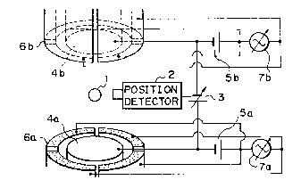
Fig. l shows the arrangement oi a prior art disclosed
in W.K. Rhlm, M. Collender, M.T. Hyson, W.T. Simms, and
~.D. Elleman, "Development of an electrostatic positioner ~or
space material processing~, Rev. Sci. Instrum., 56, February
1385, pp. 307 - 317). In the fi~ure, the reference numeral l
denotes a charged sample, 2 a position detector for detectlng
the position of the sample 1, and 3 a variable power supply
whose output voltage varies in accordance with the slgnal
output from the position detector 2. The reference numerals
4a and 4b denote a pair of planar electrodes which are
connected to two ends, respectlvely, of the variable power
supply 3 and disposed in opposing relation to each other, Sa,
5b DC power supplies, and 6a, 6b ring electrodes each of
which is disposed so as to surround a corresponding planar
electrode 4a or 4b and to whlch a higher voltage is applied
than that applied to the corresponding planar electrode from
the DC power supply 5a (5b).
In operation, the position of the positively charged
sample 1 isconstantly monitored by the position detector 2
and the output o~ the variable power supply 3 is controlled
so that the sample l is kept equidlstant between the upper
- 2 -
!~
... .
. ~., .
,:
....
.. .
.~ .
., .

20n~7sf,
and lower electrodes in the vertlcal dlrectlon as vlewed ln
the figure. Since hlgher voltages than those applled to the
planar electrodes 4a and 4b are applied to the rlng elec-
trodes 6a and 6b, the sample 1 ls also held stationary ln
the horizontal directlon as viewed in the Figure 1.
Thus, an experiment, for instance, in which the sample
1 held in this way is heated by irradiation with light or the
like can, for example, be carrled out at a space station.
The conventional levitator arranged as described above
suffers, however, ~rom the following problems. Slnce the
prior art merely controls the position of the sample through
the planar and ring electrodes, it ls incapable of rotating
the sample in a controlled manner to heat it uni~ormly. In
addition, the prior art is incapable of preventing a micro-
gravity condition, which ls a slgnificant feature o~ material
science e~periments in space, from be~ng destroyed by the
spontaneous rotation o~ the sample itself due to convection,
~or instance.
SUMMARY OF THE INVENTION:
Under these circumstances, it is a primary object of
the present invention to provide a levitator which is capable
o~ rotating the sample in a controlled manner and hence
uni~ormly heating the sample in a microgravity environment
for experimental purposes.
To this end, the present invention provides a
levitator having a position detector for detecting the
position o~ a sample, a variable power supply whose output
voltage varles in accordance with the signal output from the
- 3 -
.~
i.
.~

2.00~78~
position detector, a pair of planar ele trodes connected
to two ends, respectively, of the varia~le power supply
and disposed ln opposing relation to ea^h other, and a ring
electrode disposed so as to surround ea^h of the planar
electrodes and to which is applied a hi~her voltage than that
applied to the corresponding planar electrode from a DC power
supply, thereby holding the sample stationary at a desired
position by means of the planar and ring electrodes, wherein
the ring electrode is divided into a plurality of circular
electrodes and an alternating power supply whose output
voltage changes periodlcally is connected to each pair of
ad~acent circular electrodes.
Thus, the divided ring electrodes, that is, the
circular electrodes, serve both as a mechanis~ for holding
the sample stationary in the horizontal directlon and as a
mechanism for rotating the sample in a controlled manner.
It is therefore possible to prevent spontaneous rotation
of the sample and also to rotate the sample in a controlled
manner by applying an alternating electric field to each pair
of ad~acent circular electrodes from the alternating power
supply.
In another embodiment of the present invention, at
least one electromagnet is disposed at a predetermined posi-
tion outside the ring electrode and the sample is rotated in
a controlled manner by means of the magnetic field produced
from the electromagnet.
By changing the magnetic field distribution by utlliz-
lng the law of electromagnetic induction by electromagnets, a
- 4 --
,,
,, .

200~
current ls generated ln the sample and the sample ls rotated
in a controlled manner by way of the interaction between the
current and the magnetic field.
In still another embodiment of the present invention,
there is provided an irradiator which irradiates a levitated
sample with a plurality of high-output beams from different
directions to apply only rotational force to the sample.
High-output beams output from the irradiator are
applied to a levitated sample from a plurality of directions.
thereby applyin~ rotational force to the sample. In this
case, rotational force alone is applied to the sample by
the irradiation with the high-output beams but no force for
linear movement is applied to the sample.
In a further embodiment of the present invention,
there ls provided a permanent magnet which ls driven so as
to rotate while applying a magnetic field to the space in
which the sample is located.
As the permanent magnet that applies a magnetlc field
to the space including the sample is rotated, eddy current
2~ ls generated in the sample and this eddy current and the
magnetic ~ield interact with each other to cause Lorentz's
~orce to act on the sample ln the same direction as the
direction o~ rotation of the permanent magnet, thus causing
the sample to rotate.
. ~ .
... .
~ ~ .
. .
~ .
' '

2004786
In one aspect, the present invention provides a
levitator having a position detector for detecting the
position of a sample, a variable power supply whose output
voltage varies in accordance with the signal output from the
position detector, a pair of planar electrodes connected to
two ends, respectively, of the variable power supply and
disposed in opposing relation to each other, and a ring
electrode disposed so as to surround each of the planar
electrodes and to which a higher voltage is applied than
that applied to the corresponding planar electrode from a DC
power supply~ said planar and ring electrodes defining means
for holding the center of gravity of said sample stationary
at a desired position, wherein the improvement comprises
means separate from said sample for generating a magnetic
field about said sample for controlling rotation of said
sample about an axis through the center of gravity.
In another aspect, the present invention provides a
levitator having a position detector for detecting the
position of a sample, a variable power supply whose output
voltage varies in accordance with the signal output from the
position detector, a pair of planar electrodes connected to
two ends, respectively, of the variable power supply and ~
disposed in opposing relation to each other, and a ring
electrode disposed so as to surround each of the planar
electrodes and to which a higher voltage is applied than
that applied to the corresponding planar electrode from a DC
power supply, thereby holding the sample stationary at a
.- .
,

2004 7~f)
desired position by means of said plan~- and ring
electrodes, wherein the improvement conprises means for
rotating said sample being held statior~ry, wherein said
ring electrode comprises a plurality of arc-shaped
electrodes, and said means for rotatin~ the sample comprises
an alternating power supply having an cutput means for
providing an output voltage that changes periodically, said
output means being connected to each pair of adjacent arc-
shaped electrodes of said ring electro~e.
In a further aspect, the preseht invention provides
a levitator for levitating and rotatin~ a sample,
comprising: a position detector for detecting the position
of said sample and for generating a co~and voltage on the
basis of said position, a plurality of electrodes disposed
in opposing relationship, and responsive to said command
voltage to generate a magnetic field therebetween for
holding the center of gravity of said sample stationary in a
desired position, and means separate from said sample for
generating a magnetic field about said sample for
controlling rotation of said sample abcut an axis through
the center of gravity.
In a further aspect, the presert invention provides
a levitator for levitating and rotating a sample
comprising: a position detector for detecting the position
: 25 of said sample and for generating a sicnal indicative of
said position, a variable power supply having output means
for providing an output voltage that varies as a function of
- 5b -
. . .
.,
, . .
, .~. .

2004 78r)
the signal generated by said position de'ecting means, a
pair of planar electrodes disposed in o~oosing relation to
each other, and connected to said outpu means, a pair of
ring electrodes disposed so as to surro~nd respectively each
of said planar electrodes, means for ap~lying a direct
current voltage to each of said ring el~ctrodes, said direct
current voltage higher than the voltage applied to its
corresponding planar electrode by said ~riable power
supply, whereby the center of gravity of said sample is held
stationary in a desired position, and m~ans separate from
said sample for generating a magnetic f~eld about said
sample for controlling rotation of said sample about an axis
through the center of gravity.
The above and other objects, fectures and advantages
of the present invention will become more apparent from the
following description of the preferred ~bodiments thereof,
taken in conjunction with the accompanying drawings, in
;~ which like reference numerals denote li~e elements.
DESCRIPTION OF THE PREFERRED EMBODIMENT~:
One embodiment of the present ir-~ention will be
described below with reference to Fig. 2, in which the same
- 5c -
A
.
,
:~.
:.. ..
, ~ .
... .

200478h
elements as those shown in Fig. 1 are denoted by the same
reference numerals. In Fig. 2, the reference nu~erals 7a and
7b denote alternating power supplies whlch are connected in
series to the DC power supplies 5a and 5b, respectively, and
~ a ring electrode which is disposed so as to surround each
o~ the planar electrodes 4a and 4b, the electrode 6 compris-
ing four circular electrodes obtained by dividin~ it. Each
pair of ad~acent circular electrodes are connected to the
opposite poles, respectively, o~ the corresponding one o~ the
alternating power supplies 7a and 7b.
The peak value of voltage of the alternating power
supplies 7a and 7b is set so as to be lower than the output
voltage of the DC power supplies 5a and 5b.
In operation, the position of the sample 1 positively
lS charged is constantly monitored by the position detector 2
and the output o~ the variable power supply 3 is controlled
so that the sample 1 is kept equidistant between the upper
and lower electrodes in the vertlcal direction as viewed in
the figure. Since the voltage applied to the ring electrode
6 is higher than that applied to the planar electrode 4 even
when the output o~ the alternating power supply 7 is at its
lowest, the sample 1 is also held stationary in the horizon-
tal dlrection as viewed in the figure.
In addition, the rotation of the sample 1 can be
controlled by properly ad~usting the frequency and voltage
o~ the alternating power supply 7. Since the charge on the
sample sur~ace rotates together with the sample 1, it is
possible to obtain stable rotary motion which is synchronous
-- 6 --
.:
.

;:`o~ y~i
with the frequency of the alternating power supply 7. Assum-
ing that the number of circular electrodes constituting in
combination the ring elec~rode 6 is n and the frequency of
the alternating power supply 7 ls f, the sample 1 rotates at
a number of revolutions expressed by nf.
Thus, an experiment in which the sample 1 held in this
; way is heated by irradiation with light or the like can be
effectively carried out at a space station, for lnstance.
Although in the foregoing embodiment a ring electrode
is di~ided into a plurality of clrcular electrodes to serve
as both a mechanism for holding the sample stationary in the
horizontal direction and a mechanism for rotating the sample
in a controlled manner, lt should be noted that the same
advantageous effect can be obtained by separately disposing
electrodes ior rotation control and independently connecting
alternating power supplies to these electrodes.
Although in the foregoing embodiment a plurality of
circular electrodes constituting a ring electrode are cycli-
cally disposed, these electrodes need not be arranged in a
strictly cyclical manner.
Another embodiment of the present inventlon will next
be explained with reference to Figs. 3, 4(A) and 4(B).
Fig. 3 schematically shows the arrangement of the
second embodiment of the levitator according to the present
invention, and Figs. 4~A) and 4tB) show the relationship
between the magnetic field and the force acting on the sample
shown in Fig. 3. Referring to these figures, the levitator
according to this embodiment has electromagnets 10, 11, 12
.'.
,, .
: ,s

~`O 0~7~J
and 13 for rotation which are respectively comprised of four
equally spaced solenoid coils disposed at respective posl-
tions around one ring electrode 6a.
The following is a description of the operation of the
levitator according to this embodiment arranged as descrlbed
above.
The electrodes 4a, 4b, 6a and 6b and the operation of
holding the sample 1 stationary are the same as those in the
prior art.
With the sample 1 being levitated and held stationary
between the disk electrodes 4a and 4b, the electromagnets lO,
11, 12 and 13 are respectively fed with AC currents which
have the same period and the same amplitude and are 90 out
of phase with each other, Figs. 4~A) and 4tB) show the force
acting on the sample 1 when the N pole is formed at the upper
end of the electromagnet lO, the S pole is formed at the
upper end of the electromagnet 12, the electromagnet 11 is in
a transient state ~rom the S pole to the N pole at the upper
end and the electromagnet 13 is in a transient state from the
N pole to the S pole at the upper end, as shown in Fig. 3.
Referring to Flgs. 4(A) and 4(B), the overall magnetic
field that is generated from the electromagnets 10, 11, 12
and 13 may be decomposed into two components, that is, the
component Bv in the vertlcal direction and the component Bh
in the horizontal direction which intersects the electro-
magnets 10 and 11. The arrows in these flgures express eddy
currents locally induced by the changing magnetic fields Bv
and Bh. The overall eddy current may be decomposed into two
. .
."
~, .
.,
...
. .

~0047~
components, that is, the current Iv in the vertlcal dlrection
and the current Ih in the horizontal direction.
In accordance with the law of electromagnetic induc-
tion, the interaction between Bv and Iv produces the ~orce
Fv, while the interaction between Bh ànd Ih produces the
~orce Fh, which ~orms a rotational force.
Although in the ~oregoing embodiment four electro-
magnets are disposed in the horizontal plane, ~t should be
noted that, if eight electromagnets are employed as shown in
Fig. 5 and among them ~our appropriate electromagnets, e.g..
the electromagnets 10, 13, 14 and 17, are combined together,
it is also possible to rotate the sample 1 in the vertical
direction. If the electromagnets 10, 13, 15 and 16 are
combined together, the sample 1 can be rotated in a 45-
inclined plane.
Although in the ~oregoing embodiments four or eight
electromagnets are provided, the number of electromagnets
employed may be one or any plural number other than four or
eight.
Although in the foregoing embodiments electromagnets
are disposed around a ring electrode, these electromagnets
may be disposed between the disk electrode and the ring
electrode.
Although in the ~oregoing embodiments disk and ring
electrodes are pro~ided, either disk or ring electrodes alonemay be provided.
Still another embodiment of the present invention will
next be explained with re~erence to Fig. 6, in which the same
.; .
~,
.. . . .
.,, - ~ .

~0047~;
reference numerals as those shown in Fig. l denote the same
or corresponding elements. The reference numerals 20 and 21
denote laser beams which are applied to the sample l from
different direc~ions to apply only rotational force to the
sample l. The reference numerals 22 and 23 denote laser
oscillators for outputting the laser beams 20 and 21, respec-
tively, the laser oscillators 22 and 23 being arranged such
that the respective focal lengths and irradiation positions
of the laser beams 20 and 21 can be adjusted as desired. For
example, the laser oscillators 22 and 23 are adjusted so that
the laser beams 20 and 21 having the same output level are
applied to two irradiation points, respectivelY, which are
in symmetry with each other with respect to the center of
gravity of the sample l and are applied in mutually opposing
directions which are close to the tangential lines of the
sample l to the two symmetrical points.
With the sample l bqing levitated and held stationary
in the same way as in the prior art, one irradiation point
on the sample l is irradlated with the laser beam 20 from
the laser oscillator 22 in a direction which is close to the
tangential line of the sample l at this irradiation point.
In addltion, another irradiation point which is in symmetry
with the first irradiation point with respect to the center
of gravity of the sample l is irradiated with the laser
beam 21 from the laser oscillator 23 in a direction which
is opposite to the direction of the laser beam 20 and which
is close to the tangential line of the sample l at the
; second irradiation position. In consequence, the sample l
-- 10 --
, .
,, .
'
. ~ .

~.00~'7.~i
is rotated around its vertlcal by the laser beams 20 and 21
axis without changing its pOSitiOII thereof. In other words,
the sample l is rotated by the laser beams 20 and 21 but no
~orce for linear movement is applied to the sample l.
It should be noted that, if the laser oscillators 22
and 23 are adjusted so that the laser beams 20 and 21 are
applied to the lower and upper sides, respectively, o~ the
sample l, then the sample l can be rotated around its hori-
zontal axis. It is possible to rotate the sample l in any
direction desired by a method similar to the above.
Thus, the sample l ls ~orced to rotate in any direc-
tion desired by irradiation with the two laser beams 20 and
21, thereby enabling the direction of the sample l to be
changed as desired.
Although in the foregoing embodiment two laser beams
20 and 21 are employed, three or more laser beams maY also
be employed. In the above-described embodiment, the present
invention is applied to an electrostatic levitator, but it
may similarly be applied to an electromagnetic levitator;
in such a case also, the same advantages as those reali~ed
in the foregoing embodiment are obtained. Although in the
~oregoing embodiment the laser beams 20 and 21 are emploYed
as high-output beams ~or applying rotational force to the
sample l, other high-output beams, for example, charged
particle beams, may also be employed to obtain the same
e~fects.
Fig. 7 shows a further embodiment of the present
invention, in which the same reference numerals as those

~0~)4~7~;
in Fig. 1 denote the same or correspondlng elements. The
reference numeral 22 denotes a perm~nent bar magnet which is
disposed so as to intersect at right angles with the mutual
central axis O of the electrodes 4a, 4b, 6a and 6b and in
bisymmetry with respect to the central axis O, the permanent
magnet 22 being driven to rotate around the central axis 0 by
a driving means (not shown).
While the sample 1 is being levitated and held
stationary, the permanent magnet 22 is rotated, for instance,
in the direction of the arrow A shown in Fig. 7. In conse-
quence, the sample 1 rotates in the same direction as the
direction of rotation of the permanent magnet 22 in accor-
dance with the law of electromagnetic induction.
Flg. 8 shows the force acting on the sample 1 by the
action of magnetic induction, in which ~ denotes the direc-
tion of magnetic field of the permanent magnet 22, ~ the
current component, among the eddy currents generated as a
result of the change in magnetic field of the permanent
magnet 22, which produces rotational force, and ~ the force
acting on the sample 1 by interaction between the eddy
current ~ and the magnetic ~ield ~. It should be noted that
the action of electromagnetic induction in this case is
considered on the equator of the sample 1.
Fig. 9 shows another form of the embodiment shown in
Fig. 7, in which a U-shaped permanent magnet 23 is employed
in place of the permanent bar magnet 22 and the permanent
magnet 23 is disposed between the disk electrode 4a and the
ring electrode 6a so as to rotate around the central axis O.
- 12 -
,
.

In this case also, lt ls posslble to obt~ln the same
advantages as those reallzed ln the ~oregoing embodiment.
~lthough in the arrangement shown in Fig. 9 the permanent
magnet 23 is disposed between the two electrodes 4a and 6a,
it may be disposed outside the ring electrode 6a.
Flg. lO shows another form of the embodiment shown
in Fig. 7, in which the disk electrode 4a is ~ormed from a
permanent magnet to replace the permanent magnet 22 and this
electrode 4a is driven to rotate around the central axls O.
This arrangement also enables the same advantages as those
realized in the ~oregoing embodiment to be obtained.
Although in the fore~oing embodiments the sample l is
rotated around the central axis O, if the plane of rotation
of the permanent magnet i9 changed to another plane, for
example, the vertical plane, it is possible to rotate the
sample l in a di~erent direction from the above.
As has been described above, it is possible according
to the present invention to rotate the sample in a controlled
; manner and hence to carry out an experiment in which the
sample is uniformly heated in a microgravity environment.
Although the present invention has been described
through specific terms, it should be noted here that the
described embodiments are not necessarily exclusive and that
various changes and modi~ications may be imparted thereto
without departing from the scope of the invention which is
limited solely by the appended claims.
- 13 -
.,
: ' .

Representative Drawing
A single figure which represents the drawing illustrating the invention.
Administrative Status

2024-08-01:As part of the Next Generation Patents (NGP) transition, the Canadian Patents Database (CPD) now contains a more detailed Event History, which replicates the Event Log of our new back-office solution.

Please note that "Inactive:" events refers to events no longer in use in our new back-office solution.

For a clearer understanding of the status of the application/patent presented on this page, the site Disclaimer , as well as the definitions for Patent , Event History , Maintenance Fee  and Payment History  should be consulted.

Event History

Description Date
Inactive: Expired (new Act pat) 2009-12-06
Inactive: IPC from MCD 2006-03-11
Inactive: Late MF processed 2003-11-24
Grant by Issuance 1993-12-21
Request for Examination Requirements Determined Compliant 1990-07-31
All Requirements for Examination Determined Compliant 1990-07-31
Application Published (Open to Public Inspection) 1990-06-07

Abandonment History

There is no abandonment history.

Fee History

Fee Type Anniversary Year Due Date Paid Date
MF (patent, 8th anniv.) - standard 1997-12-08 1997-11-17
MF (patent, 9th anniv.) - standard 1998-12-07 1998-11-18
MF (patent, 10th anniv.) - standard 1999-12-06 1999-11-17
MF (patent, 11th anniv.) - standard 2000-12-06 2000-11-17
MF (patent, 12th anniv.) - standard 2001-12-06 2001-11-19
MF (patent, 13th anniv.) - standard 2002-12-06 2002-11-19
MF (patent, 14th anniv.) - standard 2003-12-08 2003-11-24
MF (patent, 15th anniv.) - standard 2004-12-06 2004-11-08
MF (patent, 16th anniv.) - standard 2005-12-06 2005-11-08
MF (patent, 17th anniv.) - standard 2006-12-06 2006-11-08
MF (patent, 18th anniv.) - standard 2007-12-06 2007-11-09
MF (patent, 19th anniv.) - standard 2008-12-08 2008-11-10
Owners on Record

Note: Records showing the ownership history in alphabetical order.

Current Owners on Record
NATIONAL SPACE DEVELOPMENT AGENCY OF JAPAN
Past Owners on Record
KAZUNORI IKEGAMI
KENJI ITOGA
SHINICHI YODA
SOUICHIRO OKUDA
Past Owners that do not appear in the "Owners on Record" listing will appear in other documentation within the application.
Documents

To view selected files, please enter reCAPTCHA code :


To view images, click a link in the Document Description column. To download the documents, select one or more checkboxes in the first column and then click the "Download Selected in PDF format (Zip Archive)" or the "Download Selected as Single PDF" button.

List of published and non-published patent-specific documents on the CPD .

If you have any difficulty accessing content, you can call the Client Service Centre at 1-866-997-1936 or send them an e-mail at CIPO Client Service Centre.


Document
Description 
Date
(yyyy-mm-dd) 
Number of pages   Size of Image (KB) 
Abstract 1997-09-21 1 21
Claims 1997-09-21 15 421
Drawings 1997-09-21 9 140
Representative Drawing 2000-02-28 1 9
Descriptions 1997-09-21 16 524
Fees 1996-11-17 1 83
Fees 1995-11-19 1 93
Fees 1993-10-07 1 42
Fees 1994-11-12 1 82
Fees 1992-11-08 1 39
Fees 1991-10-29 1 42
PCT Correspondence 1993-09-22 1 34
Courtesy - Office Letter 1990-03-11 1 44
Courtesy - Office Letter 1990-11-13 1 22
Examiner Requisition 1993-03-14 1 64
Prosecution correspondence 1990-07-30 1 31
Prosecution correspondence 1993-06-15 3 79