Note: Descriptions are shown in the official language in which they were submitted.
FF~Or1 E:p~,~rW Rr~ [,=.tir.___ ~~4~i~).~~~~ F'.
1
This invention relates to the treatment oP water, particu-
larly water intended far use in fig;h farming plants. More
explicititely the invention relates to a method for water
treatment comprising aeration of tree water to be treated and
causing it to circulate to a chamber, into an adjacent basin of
considerably larger volume than that of the chamber and back to
the chamber, said aeratiOrl producing bubbles acting to form a
foam containing dissolved impurities at the surface of the
water in the chamber, and removing said foam from the chamber
as it is formed.
A such method is disclosed in Norwegian patent No. 58 99G.
According to this patent the circulation of the water is
provided by an external water pump in which also the air for
aeration of the water is added before the water is ejected into
an upper portion of the chamber, closely below the foam formed
by the air bubbles.
Here it should be generally noted that water treatment
based on air bubbles rising in water takes place by two
strictly distinguished phenomena or mechanisms termed flotation
and physical adsorption respectively, which, dependent on the
size of the bubbles, take care of different farms of impurities
in the water. Thus, flotation is used to remove particulate
organic and inorganic material suspended in the water, while
physical adsorption extracts dissolved organic and inorganic
substances in the water.
Flotation utilizes the ability of the suspended particles
to rise to the surface of a liquid. For this to happen the
density of the particles must be lower than that of the liquid
or they must be able to be lifted to the surface by gas bubbles
enclosing or adhering to the material which settles as a slurry
deposit on top of the water from where i.t can be removed.
However, the water surface must be relatively calm as otherwise
the slurry will disintegrate.
In physical adsorption, polarized compounds dissolved in
the water associate with the air bubbles which bring them to
the surface where they are collected in a voluminous bubble
foam that ie easily removed.
The flotation process uses air bubbles ranging from about
~e~~~~'~~~r~
2
0,03 mm up t0 about 0,12 mm in sizFZ, while the pysical adsorption
process is most affective with bubbles of a size around o,8 mm.
Norms?.ly the air bubblesc for flotation are produces by
dissolving air in water that is put under a pressure of several
atmospheres, and then releasing the pressure to form slowly
rising gas bubbles of the above site due to supersaturation.
As an example of this flotation technique it is referred to SE
patent No. 169 5G1 which relay on the use of pumps, valves,
water pipes and pressure chamber. Also, in connection with fish
farming this conventional flotation method will poison the
water if air is used as gas medium, since the water will become
supersaturated with nitrogen gas.
The bubt~les used in physical adsorption axe normally
produced by an air diffusor, i.e. a tube, hose or similar
having air permeable walls, positioned at the bottom of a
column of polluted water. For a more detailed desscription of
physical adsorption it is referred to the book '°Seawater
Aquariums" by stephen Spotte, John Wiley & Sans, 1979, p. 208 -
2i7.
A closer study of the description of the above Norwegian
patent No. 58 996 will make it clear that, although it is not
directly mentioned therein, it obviously relies on physical
adsorption of the dissolved substances rather than on flotation
of particulates. Thus, it mentions that the bubbles in the
surface foam easily burst and the foam collapses, which is
typical for a foam formed through physical adsorption with
large bubbles; and further that the tiny air bubbles (which
could cause flotation) are considered as a problem and therefore
should be remaved by means of a sponge filter in the chamber
while particulate material is removed by an external mechanical
filter. Furthermore the fact that the Water is ejected into
the chamber close to the water surface therein will cause a
turbulence destroying any flotation effect that might emerge.
Consequently the patent teaches that the foam has to be rapidly
removed to prevent the impruities from returning into the
water. (Physical adsorption in contradiction to chemical
adsorption is a reversible process using weak bonds as those
formed by van der Waals forces). Therefore this prior water
,; '.j ~_> _ .. °r ~._:e.t ~zs~rr.-_~, :y hih_IIJ;,a:a noaj
3
treatment method which, according 'to the patent was proposed
more than 50 years ago, does not produce water of a quality
satisfying the demands of modern, full scale fish breeding
plant, since the retension time of the particulate material in
the system is too long while also 'the material easily accumulates
within the fish basins. Furthermore ammonia will also accumulate
in the system.
Tile object of the present invention is to provide an
improved water treatment method that in addition to being less
expensive than the prior method according to the above Norwegian
patent also give a far better result as to the quality of the
water.
'This object is achieved by a method as mentioned in the
introduction, characterized by causing said aeration and
circulation by means of an air diffusor located near the bottom
of the chamber to produce bubbles therein of a size substantially
in the range of 0,03 mm to 1 mm, the larger size bubbles of which
are effective t4 farm said foam on top of the chamber, transfer-
ring the remaining smaller size bubbles together with particu-
lates into the basin entrained in the water flow to form at the
surface of the water in the basin a flotation slurry containing
particulate impurities, and removing said slurry from the basin.
Thus, contrary to what happens in the prior process of the
Norwegian patent, according to the present invention the
particulate material is continuously removed as soon as it is
formed and is not allowed to disintegrate or accumulate in the
fish tanks or basins.
Further advantages compared to the above prior technique
is elimination of the need for any mechanical pumpe to circulate
the water or to pressurize the water to Cause flotation. Also,
the water layQr at the top of the basin in which the flotation
slurry containing the impurities is formed is not subject to
turbu~,enoe interfering with the flotation process. By allowing
the top water layer in the chamber to flow over into the
adjacent, considerably larger basin, the flotation effect is
optimized under the calm flow conditions prevailing in the
basin, and preferably the flotation slurry is not removed until
FFpFI eF~~:cesrus~ c,~at3._. t9a:~-,. v2. °. t.r: r~~ F. E.
~,( ~~)r'~~~~. l
4
it has reached the other side of the basin opposite from the
chamber.
Tn a preferred embodiment of i~hs method according to the
invention the water in the chamber is caused to flow upward
through a biological filter medium (biofilt.er) further acting
to remove dissolved organic matter in the water and tv transfer
ammonium into nitrate. (mhe latter affect is the most important
one in this case Since, as explained above, the dissolved
organic matter is removed through physical adsorption.)
Further, ammonia is removed by the biofilter.
Admittedly, utilizing a such biofilter is not a new
concept in connection with water treatment plants, in which the
deposit on the filter, upon reaching a certain thickness, is
broken away in smaller or larger bits or fragments that are
entrained in the water stream to partly settle at the bottom of
a suitable container ar the like from which they may be removed
together with other settle foreign particles settled from the
water. However, in a conventional installation 70 - 9p ~ of
the capacity of the biofilter is used to decompose dissolved
organic matter while 10 - 30 ~ is used to remove ammonium.
Also, some of the broken away material will tend to resist
settling and therefore flow with the discharge water to the
recipient, 4r result in a poor quality of the water in the fish
tanks. ~y using a biofilter in Combination with the above
described adsorption and flotation processes according to the
invention most of the capacity of the biofilter is utilized .for
removing ammonium, and consequently the size of the filter may
be considerably reduced. Further, the cleaning effect of the
filter is obtained without the need for a separate settling
basin since all of the material which i.s detached from the
filter will be entrained in the upflowing water and consequently
collected in the foam and flotation slurry which is removed at
a later stage.
Treating water by means of air diffusors of the type used
in the invention is known per se, but only with a view to
oxygenation and stripping of undesireable gasses such as C0~
and nitrogen gas and far breaking away mat-growth on the
biofilter. Examples of conventional biofiltering are also
FF.iit1 E:F"~'opqF :x::41'_.._. t~:~;=..1::. '_ IJ:Ze F'.
A'
found in 5E patents No. 169 561, 442 744, 386 658 and 382 321.
However, none of these patent, suggest biofiltering used in an
advantages combination with other water treatment processe,
such as in the present invention.
Tha invention is based on the idea that the use of a
particular air diffusor of a type known per se, which produces
air bubbles of a size varying over a relatively wide range,
will result in physical adsorption in addition to oxygenation,
gas-stripping and mat-growth detachment, while the diffuser
also serves to provide the required circulation of the water.
Tn the preferred version of the invention, in which the water
is caused to flow through a biofilter, the diffusor automati-
cally tends to reduce the load on the biofilter with respect to
deeompositian of organic matter owing to the physical adsorption
effect and also provides for the required removal of mat-growth
on the biofilter. Discharging the water from the chamber into
a larger basin results in the further advantage that also the
polluted fragments that are broken away from the biofilter will
be entrained in the natural water flow and ba floated in the
basin allowing the fragments to be removed by conventional weir
technique rather than having to pump the water to a separate
processing unit for separation i.e. by settling or mechanical
filtration. This, in turn, results in a lower pump energy demand
than in a conventional water treatment plant based on separate
processes with the pumping of water between the various
processes. also should be mentioned here that the treatment
efficiency achieved by flotation on this type of particles,
{mat growth particles and crushed organic small size particles)
is extremely high compared to i.e. conventional sedimentation,
and a sedimentation basin dainbg something close to the same
hod would normally have to be 10 - 20 times bigger. Thus, the
invention provides a simple, compact and effective water
treatment system basically consisting of a single processing
unit, with exceptionally low investments and operational costs,
compared to prior water treatment systems of more recent type
based on the normal use of sequential arranged unit processes.
The recirculation type water treatment plants for fish
farming used until now normally are based on separate units for
FFOO gp';'IINRF O::J1'..:~_ 1~'c'..12. ' 1-t:al F, r
6
biofiltering, oxygenation, degassing of COZ and nitrogen gas
and particle separation through mechanical filter mesh or by
sedimentation. The costs of instal:Latian of such plants are
very high and the energy consumption due to pumping is relatively
large. As a typical example Europe's largest recirculation
fish farm plant of this kind {built in Farsund, Norway 1985 --
86), having an effective. fish basin volume of 1000 m3, costed 28
millions NOK and demands an energy consumption of about 300 -
400 kW for operation.
In comparison a plant based on the present invention.
which at present is being built with an effective fish basin
volume of 2500 m3 (i.e. about 2,5 times larger than said prior
plants will cost about 11 million NOK and have an energy
consumption of approximately 50 kW.
The invention also comprises an apparatus for carrying out
the method according to the invention, as defined in the
accompanying patent claims.
An example of the invention will now be described more fully
with reference to the accompanying, partly schematic drawing in
which:
Fig. 1 is a plan view of a turbot fattening plant based on
the method and plant according to the invention, and
Fig. 2 is an enlarged scale cross-sectional view through the
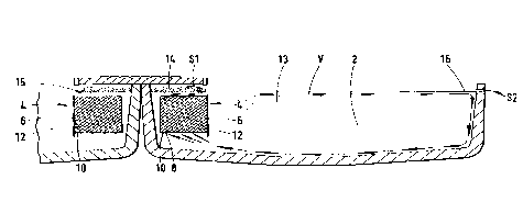
plant taken on the line II-TT in fig. 1.
The plant illustrated in fig. 1 is conveniently comprised
of i.e. four, substantially identical, rectangular, water
filled basins or tanks 2 each comprising an independent
fattening unit. Associated with each basin 2 is a chamber
generally denoted by numeral 4 situated at one long side of the
basin. In the embodiment as shown the chamber 4 is laterally
defined by the one long wall and two end walls of the basin and
an independent, longitudinal, impervious partition wall 6.
However, if desirable, it may of course be defined by four
separate walls independently of the walls of the basin. The
upper and lower surface of the partition wall 6 are spaced from
the upper edge and bottom respectively of the basin 2, so that
the chamber 4 communicates with the basin 2 at the top as well
as at the bottom therROf.
FROf1 ER';NN:7F~ it241':::'.. 198~~.l;_. '. l.t:y F'.
~~e ~ !
Disposed at the t~ottorn of the chamber 4 there is, according
to an important feature of the invention, art air diffusor 8
consisting e.g. of several pipes or hoses of which the walls
are provided with a large number of minute apertures or pores
capable of producing air bubbles in the range of about 0,03 mm
to about Z mm. Thus, the diffusor wall apertures should be
microscopic, i.e. 0,1 - 0,3 Vim, normally requiring the air
blown therathrough to be pre-filtered in order to prevent
clogging of the apertures or pores. As an example of a
diffusor well adapted for use with the invention it is referred
to that which as sold under the trade name "oxyflo", delievered
by Gardentec of Sweden among others, which consists of stretched
arid oriented polyethylene fibres bonded together in a random
pattern.
Preferably the chamber 4 is filled with a biological
filter medium 12 (indicated by hatching in the drawings) held
in place by support members 10, a.g. in the form of a screen.
The surface area of the filter medium 12 should be as large as
possible relative to its volume, with a view to microbiological
growth. Preferably, the filter medium 12 is of a type which
incorporates upwardly extending, intercrossing channels ("cross
flow system°') in order to secure conditions promoting physical
adsorption, to prevent the smallest air bubbles from attaching
to the biofiltermedium, and to secure supply of water and air
to all parts of the filter. As an example of a suited filter
medium it is referred to the product sold under the trademark
°°Muntars" supplied by AB Carl Munters, Sweden or "Texrapac"
supplied by Terraoon, West-Germany.
The purpose of the basin 2 is partly to provide a retention
time for the dirty water sufficient to secure an effective
flotation process, partly to effect bi-processing purposes and
partly to serve as a fattening tank etc. The volume of the
basin will depend on the water quality characteristic, the
desired rest concentration etc, and it has to be individually
dimensioned in each separate case. Its shape will depend on
the purpose, on whether the basin is outdoor or indoor, in
existing buildings or whether the process is to be placed in
existing basins etc. 2'hus, although the shape of the basin 2
FF'iyl _FR'~'tIW vF' si::.lt'.:~'. l92'3.1,~. ~ lv:~. P.IO
~~~~~1.'~
8
shown in the drawings is rectangular it is also possible to use
l.e. a circular configuration, in which case also the chamber 4
normally will be circular and centrally areanged in the basin.
When used for internal water treatment in fish farming the
water basin 2 normally will function as a breeding tank.
Somewhat simplified, what happens in the chamber 4 is as
follows:
awing to the air diffusor 8, polluted, low oxygen water is
drawn (by means of the "mammut pump's or "air pump" principle)
from the bottom of the basin 2 under the partition wall 6 and
into the bottom of the chamber 4. The water passes up through
the chamber and provides nourishment for a microorganism flora
on the surface of the filter medium 12. This microorganism
flora converts biodegradable dissolved organic matter to a mat--
growth on the surface of the medium and transforms ammonium
into nitxata form. The microscopic air bubbles from the
diffusor 8 oxygenate the water and provides an ample supply of
oxygen to the microorganism flora and breaks away the mat--
growth when the latter has reached a certain thickness, (Ample
oxygen supply and limited mat-growth thickness are essential
factors in order to achieve maximum microbiological growth.)
Physical adsorption of dissolved organic compounds is obtained
(according to the litterature reference mentioned in the
introduction most effectively on bubbles with a size of 0.8 mm)
to form a bubble foam 14 containing dissolved substances from the
water. The foam 14 is lead by gravity into a channel 15 as
indicated by arrow S1 and is then discharged from the plant for
further sludge treatment. The strong water-air stream thus
formed (which breaks away the mat-growth and also contains the
particulate impurities that are drawn in at the bottom as
indicated by the arrow V in fig, 2) will also contain a large
percentage of bubbles having an optimum size for flotation
(O, p3 - 0,120 mm). Even within the chamber some of those
bubbles will attach to the particulate material while the
remaining minute bubbles will flow with the water-particle stream
into the basin 2. Zn the latter basin the remaining minute
bubbles will attach to particulate material 13 and, in addition,
in the basin there are calm hydraulic conditions ideal for
FFf~it c.'~'Lia:W ~.i~.li_,=... l~~...I~~. _ 11:24 F'.11
r!-.~w~~~~~~~~~~
9
flotation of the particulate impurities which ultimately will
form a flotation slurry 1~ which, owing to the natural flow of
water in the basin, will flow to a place where it can be
skimmed off by weir technique as indicated with the arrow S2.
When the water flow (provided by the air bubble pumping effect)
reaches a wall sur~aae in the basin 2 it will follow the wall
down towarQ the bottom (see fig. 2) and in the same manner
return along the bottom brack to the inlet of the chamber 4
under tho partition wall 6. This bottom flow will pick up the
particles settled on the bottom and bring them into the chamber
4 in which they, due to the above described processes, ultimately
are incorporated in the flotation slurry. It should also be
noted that awing to the physical adsorption of dissolved
organic substances a considerable reduction of the size of the
biofilter will be possible since the load on the biofilter will
be reduced. As explained above, normally 70 - 90 ~ of the
capacity of the biofilter is used to break down organic matter,
while only l0 - 30 ~ is used to transform ammonium into nitrate.
A21 in all a number of biological and physical-chemical
fenomena interact in this method and provides a combined
treatment result that until now no prior unit process has been
able to pravida.
The invention is applicable to virtually all types of
waters in which it is desirable to remove biologically decompos-
able unstabla organic matter, non-decomposable dissolved organic
matter and particulate organic and/or inorganic suspended
particles (even if these are micrasaapic and not easily
settled). In addition the process transforms the toxic
ammonium compound into the mare non-toxic nitrate form. The
water should however not contain any compounds toxic to
bacteria, The water treatment according to the invention is
suitable for internal or external water treatment in fish
farming plants and in treatment of municipal and industrial
waste waters.