Note: Descriptions are shown in the official language in which they were submitted.
20~)5041.
i~
POSTURIZED SPRING BEDDING PRODUCT
This invention relates to spring interiors,
and specifically to spring interiors for bedding
products, such as mattresses and the like.
A known form of spring interior comprises a
plurality of longitudinally extending bands of springs
disposed side by side and connected together by
helical wires which extend transversely of the bands
and embrace portions of the bands. Several kinds of
bands of springs have been proposed for incorporation
in spring interiors. One kind of band, which is the
subject of British patent No. 1,104,884, will
hereinafter be referred to as a band of interlocked or
interlaced springs. It comprises a single length of
spring wire shaped to form a plurality of individual
coil springs arranged in a row, one end turn of each
coil spring lying adjacent to a top face of the band
and the other end turn of each coil spring lying
adjacent to a bottom face of the band, each coil
spring being of a rotational hand opposite to the
rotational hand of the adjacent coils immediately
before and after it in the row, and being joined to
~'
20050~.
~_,
--2--
the adjacent coil springs by a pair of interconnecting
segments of wire integral with the coil springs. One
of the pair of interconnecting segments is located in
the bottom face of the band, and the other of the pair
of interconnecting segments is located in the top face
of the band. Each interconnecting segment comprises a
bridging portion between adja~ent coils, which
bridging portion extends lengthwise of the row.
When bands of interlocked springs of the
type described hereinabove are assembled to form a
spring interior, they are disposed side by side and
interconnected by helical wires, some of which lie in
the top face of the spring interior and others of
which lie in the bottom face thereof, the top and
bottom faces of the spring interior being the faces
defined by the top and bottom faces of the bands
incorporated in the spring interior. Each helical
wire extends across the bands of springs and embraces
portions of wires of the bands that extend
transversely of the bands from the ends of the
bridging portions of the links. In the top face of
the spring interior the helical wires are disposed at
uniform intervals along the bands of springs, the
arrangement being such that there are two springs
disposed in the interval between each helical wire and
the next. There is a similar arrangement in the
bottom face of the spring interior.
Z(:)05041.
--3--
It will be appreciated from the foregoing
description that the top face of a spring interior
assembled in this way has the general appearance of a
rectangular grid. Each of the transverse elements of
the grid comprises a helical wire, and each of the
longitudinal elements of the grid comprises a row of
mutually aligned bridging portions. Within the
confines of each rectangle of the grid and disposed a
little lower than the grid are the upper end portions
of two adjacent coil springs, those two springs
constituting parts of the same band of springs. The
bottom face of the spring interior is, of course,
similar to the top face, though inverted.
In this description of the invention there
are references to faces of bands of springs and of
spring interiors. As the bands of springs and spring
interiors are, of course, of open-work or skeletal
form, the term "face" must be understood as referring
to an imaginary surface defined by the relevant parts
of the bands or spring interiors. Furthermore, as the
wires and helical wires are of finite width or
thickness and as they sometimes overlap each other,
the term "face" cannot be understood as having a
strictly geometrical meaning. Nevertheless, as the
faces concerned are relatively extensive and are of
flat shape, their locations can in practice be
determined without difficulty or ambiguity.
Z(~)5041.
--4--
It is customary for a bedding spring
interior to be incorporated in an upholstered article.
In such an article at least one of the main faces of
the spring interior (that is the top and bottom faces
thereof) is covered by a layer or layers of padding.
This is turn is covered by a cover made of sheet
material, such as ticking or upholstery fabric.
Pressure is applied unevenly to the top
surface of a mattress when a person reclines atop the
mattress. This uneven pressure or uneven loading of
the mattress is a consequence of the uneven weight
distribution of a person along the length of the body.
The heaviest portion of the body is located
approximately midway along the length of the body, and
consequently, a person reclining atop a mattress tends
to cause the mattress to deflect or sag to a greater
extent in the lengthwise center of the mattress than
at the ends. This uneven deflection in turn results
in a person reclining atop the mattress having an
unnatural and uncomfortable misalignment imparted to
his or her spine.
To counter this uneven deflection of a
mattress when a person is reclining atop the mattress,
! it has been proposed to reinforce or rigidify the
lengthwise center section of the mattress. Such
center section reinforcement or rigidification has
taken the form of increasing the number or density of
springs in the center section of the mattress, using
200~041.
~_,
different or firmer springs in the center section of
the mattress, or adding additional structure to the
center section to reinforce that section to a greater
extent than the end sections. All of these center
section reinforcement techniques, though, are
relatively expensive and difficult to automate.
It has therefore been an objective of this
invention to provide an improved method and apparatus
for imparting differing firmness to differing
lengthwise sections of a mattress.
Still another objective of this invention
has been to provide an improved method and apparatus
for increasing the firmness of selected lengthwise
sections of a bedding spring interior of the
interlocked spring type described hereinabove.
The invention of this application which
achieves these objectives comprises a spring interior
having a plurality of longitudinally extending bands
of interlocked or interlaced coil springs wherein the
bands are disposed side by side so that their top
faces lie in a top main face of the spring interior
and their bottom faces lie in a bottom main face of
the spring interior. The bands of springs are
interconnected by helical wires lying in the top and
bottom faces of the bands and extending across the
bands with each helical wire embracing portions of
wires of the bands that extend transversely of the
bands. In order to increase the firmness of coils in
20~504~
-_ -6-
a selected section of the spring interior, as for
example, the lengthwise, center one-third of the
spring interior, posture rods extend transversely
through overlapped portions of overlapped coils in
multiple bands of the spring interior. These posture
rods take the form of straight wire rods which extend
through or are threaded through overlapped portions of
multiple pairs of overlapped coils and are treated at
the opposite ends so as to prevent the rods from
inadvertently pulling out or being moved out from
~etween the overlapped coils. The end treatment takes
the form of either being bent into a loop at the end
or being attached at the opposite ends to border rods
of the spring interior.
The primary advantage of the invention of
this application is that it enables selected sections
or portions of spring interiors made from multiple
bands of interlocked or interlaced coils to be
inexpensively and easily increased in firmness
relative to other sections of the spring interior. It
also enables the edge of a selected portion of a
spring interior to be increased in firmness by simply
attaching the ends of multiple posture rods to the
border rods or border wires of the spring interior.
These and other objects and advantages of
this invention will become more readily apparent from
the following description of the drawings in which:
20~0~l1.
-7-
Figure 1 is a top plan view, partially
broken away, of a mattress incorporating the invention
of this application.
Figure 2 is an enlarged perspective view,
partially broken away, of a portion of two bands or
rows of springs embodied in the mattress of Figure 1.
Figure 3 is a cross-sectional view taken on
line 3-3 of Figure 1.
Figure 4 is a perspective view of a portion
of a spring interior incorporating a modified version
of the posture rods of the spring interior of
Figure 1.
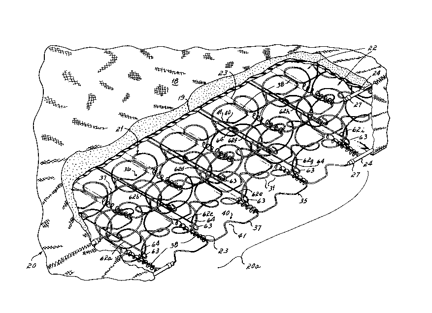
With reference first to Figures 1-3, there
is illustrated a mattress 20 embodying the invention
of this application. This mattress comprises a spring
interior 21 on the top and bottom surfaces of which
there is a pad 19. An upholstered covering 18 encases
the spring interior 21 and the pads 19.
The spring interior 21 is formed from a
plurality of bands of springs 22 which extend
longitudinally of the mattress. These bands of
springs 22 are laced together by helical lacing wires
23 which extend transversely of the spring interior
and secure the bands of springs in an assembled
relation. A border wire 24 extends completely around
the periphery of the spring interior in the top and
bottom planes 25, 26, respectively, of the interior
and is secured to the outermost edge of the spring
- 20~041
--8--
interior in these planes by conventional sheet metal
clips 27.
Each band of springs 22, a portion of one of
which is illustrated in Figure 3, is made from a
single length of spring wire shaped to form a
plurality of individual coil springs 31 arranged in a
row. Each coil spring 31 comprises about two and
one-half turns of wire. The axis of each coil spring
is not upright but is inclined slightly lengthwise of
the band, each spring being inclined in a direction
opposite to that in which its two adjacent springs in
the row are inclined. The end turns of the coil
springs 31 lie adjacent to the top and bottom faces
25, 26 of the band. Each coil spring, such as that
numbered 31b (Figure 3), is so coiled as to have a
hand opposite to the hand of the adjacent coil
springs, such as 31a and 31c, immediately before and
after it in the row. Each coil spring is joined to
the next adjacent coil spring by two interconnecting
segments 35, 36 (Figure 2) of the wire integral with
the coil springs. One of the two interconnecting
segments 35, 36 is in the top face 25 of the band 22,
and the other is in the bottom face 26 thereof. For
! example, coil spring 3la (Figure 3) is connected to
coil spring 31b by interconnecting segment 35, which
is in the bottom face of the band, and the coil spring
31b is connected to coil spring 31c by interconnecting
segment 36, which is in the top face of the band.
Z00504~
g
Each interconnecting segment 35, 36 comprises a
bridging portion 37, which extends longitudinally of
the row of coil springs and end portions 38 which
extend in a direction normal to the longitudinal axis
of the band 22. Those end portions 38 of the
interconnecting segments 35, 36 also lie in the top
and bottom faces 25, 26 of the band 22.
In the band 22 illustrated in Figures 1-4,
the location of the intersection between each end 38
of each coil spring 31a, 31b, 31c or 31d and the
associated end portion of the interconnecting segments
35, 36 is well defined, for the coil springs are
curved and the end portions 38 of the interconnecting
segments are straight. In other constructions,
however, the intersections may be less well defined
because the end portions 38 of the interconnecting
segments 35, 36 may be replaced by arcuate extensions
of the coil springs 31a, 31b, 31c; in those last
cases the interconnecting segments must be considered
as consisting solely of the bridging portions 37.
Each bridging portion 37, in addition to
extending longitudinally of the band, also extends
laterally thereof to form a supporting structure 40.
In the embodiment of Figures 1-4, the supporting
structure 40 is in the form of a V-shaped indentation
41 of wire lying in the top 25 or bottom face 26 of
the band 22, as the case may be, and extending to one
side of the remainder of the bridging portion 37 of
Z00504~
--10--
which it forms a part. Each V-shaped indentation 41
lies halfway between the end portions 38 of the
interconnecting segment of which it forms a part, and
it extends from one side face of the band toward the
other side face thereof.
The method of manufacturing and the
apparatus for manufacturing the band of springs
illustrated in Figures 1-4 is completely described and
illustrated in British patent No. 2,143,731. After
the rows of coil springs are formed, each coil spring
is interlaced with the next by having an intermediate
turn thereof passed around an intermediate turn of the
next spring. This coupling or interlacing can be
carried out mechanically or manually.
A plurality of bands of springs 22 are
assembled to form a spring interior 21. Bands of
springs 22, each similar to that shown in Figures 1-4,
are disposed side by side, and preformed helical wires
23 are attached to them. The helical wires 23 lie in
the top and bottom faces 25, 26 of the bands and
extend at right angles to the longitudinal axes of the
bands. Each helical wire 23 embraces one pair of
closely adjacent end portions 38 of each band.
It will be seen from Figure 1 that much of
the top and bottom faces of the spring interior have
the general appearance of a rectangular grid. Each of
the transverse elements of the grid comprises a
helical wire 23, with the end portions 38 embraced by
--10--
-- 2Q05041.
--1 1--
it, and each of the longitudinal elements of the grid
comprises a row of mutually aligned bridging portions
37. Within the confines of each rectangle of the grid
and disposed a little lower than the grid are the
upper end portions of two adjacent coil springs 31.
Were it not for the presence of the supporting
structure 40, the top face 25 and bottom face 26 of
the spring interior 21 would present relatively large
rectangular apertures into which upholstery material,
such as filling or padding 60, placed on top of the
top face could readily enter, thereby giving rise to
"cupping." The presence of the supporting structures
40, however, reduces any tendency to "cupping," as the
supporting structures occupy central parts of the
rectangular apertures and can serve to support the
upholstery material.
In accordance with the practice of the
invention of this application, the lengthwise center
one-third section 20a of the mattress 20 and spring
interior 21 is posturized or increased in firmness
relative to the endmost sections 20b and 20c.
"Posturization" is a term of art used to describe the
increasing of the firmness of one section of a
mattress or spring product relative to another
section. In this instance, the posturization is the
practice of increasing the firmness of the lengthwise,
centermost one-third section of the mattress. This is
the section which supports the greatest concentration
2005041.
-12-
of weight of a person reclining atop the mattress and
is therefore the section most subject to sagging or
drooping relative to the other endmost sections. To
prevent that sagging or drooping which can cause
discomfort of a person reclining atop the mattress
because of the sag or unnatural curvature of the spine
which occurs in the most heavily loaded, centermost
section of the mattress, this section is the one which
is commonly increased in firmness.
To increase the firmness of this centermost
section 20a of the mattress and spring interior 21,
the spring interior 21 includes nine posturizing rods
62a-62i which extend transversely between opposite
sides of the spring interior and pass through or
between overlapped portions 64 of overlapped
intermediate turns of coil springs 31. These rods
62a-62i are straight rods, except for the endmost
portions which, as explained more fully hereinafter,
have end treatments to prevent the rods from pulling
- 20 out of or being withdrawn from between the overlapped
portions 64 of the coils 31.
The rods 62a-62i are all identical and are,
in the preferred embodiment, of slightly heavier gauge
or diameter than the wire from which the bands 22 of
coil springs are formed, but are of less gauge or
diameter than the border wires 24 which surround the
spring interior in the top and bottom planes or faces
25, 26 of the spring interior. These rods 62, though,
-12-
- 2005041
-13-
may be of greater or lesser diameter relative to the
diameter of the wire bands 22, depending upon the
firmness desired to be imparted to the spring interior
21 by the rods.
S As explained hereinabove, the adjacent coils
of each band of coils 22 are interlaced or interwoven
to the extent of having one intermediate turn of each
coil interwoven with one intermediate turn or
revolution of each adjacent coil. That is, and with
reference to Figure 4, the coil 31b has one turn or
revolution interlaced or interwoven with the adjacent
coil 31a and another turn or revolution interwoven or
interlaced with one turn of the adjacent coil 31c.
Thus, each coil 31, except for the endmost coils of a
band of springs 22, has two turns or revolutions
interlaced with turns or revolutions of the two
adjacent coils, and the endmost coil 31 has one turn
or revolution interlaced with one turn or revolution
of the adjacent coil of the same band 22 of coil
springs. These overlapping portions 64 of the coil
springs 31 provide a passageway therebetween through
which the straight posture rods 62 are threaded or
inserted. The overlapping portions 64 of the coils of
adjacent bands are colinearly aligned and provide
aligned columns of overlapping portions 64 through
which the posture rods 62 may be, and, in fact, are,
inserted or threaded.
200~04~.
-
-14-
With reference to Figure 3, it will be seen
that in the preferred embodiment, there are nine
posture rods in the centermost one-third section 20a
of the spring interior 21. Five of these posture rods
are located in a lower horizontal plane 66 which
extends horizontally parallel to the top and bottom
faces 25 and 26 of the spring interior 21, and the
four other posture rods 62 are contained in an upper
horizontal plane 68 which is spaced from, but parallel
to, the plane 66.
With reference to Figure 2, it will be seen
that the endmost portions of each posture rod 62 are
bent into a hook-shaped end 63 so as to prevent the
posture rods from moving laterally and pulling out or
being pulled out of from petween the overlapped
portions 64 of adjacent coils. The endmost portions
63 of the posture rods 62 may be formed into a
J-shaped hook or into a loop or any other
configuration which prevents the rods from being
pulled through or being unthreaded from the passageway
between overlapped portions 64 of adjacent coils.
With reference now to Figure 4, it will be
seen that in lieu of a J-shaped hook 63 being formed
on each end of each posture rod 62, those posture rods
62 which are located in the lower plane 66 are formed
into a downwardly extending end section 70 and a
longitudinally extending endmost section 71.
Similarly, the ends of those posture rods 62 located
-14-
20~)5041
-15-
in the upper plane 68 have an upwardly extending end
section 74 and an endmost longitudinally extending
section 75. The endmost sections 71 and 75 of the
posture rods are secured by conventional metal clips
576 to the bottom and top border wires 77 and 78,
respectively.
The presence of the posture rods 62 in the
spring interior 21 functions to increase the firmness
of the coil springs and thus, of the spring interior,
in that section 20a of the mattress or spring interior
within which the posture rods are located. By
increasing the firmness of the spring interior in this
section, the mattress or spring interior is better
able to conform the top surface of the mattress or
spring interior to the spinal configuration of a
person reclining atop the mattress and to prevent
misalignment of that person's spine as a consequence
of the centermost and most heavily loaded section of
the mattress deflecting to such an extent as to cause
misalignment of the person's spine while that person
reclines atop the mattress.
While in the preferred embodiment, the
spring interior 21 has been described as containing
nine posture rods, it could, of course, contain
greater or lesser numbers of posture rods, depending
upon the length of the section to be increased in
firmness. With a greater number of posture rods, the
length of the increased firmness section 20a could be
2005041.
-16-
increased and with a lesser number, the length of the
posturized section could be decreased. Alternatively,
the rods could be placed in only the overlapped
portions 64 of the interlaced coils contained in the
uppermost plane 68 so as to increase the firmness of
that side, while leaving the other side of the
mattress relatively less firm because of the absence
of posturized rods in the lower plane 66 of the
overlapped portions of the interlaced coils of the
spring interior.
~ hile I have described only two embodiments
in my invention, persons skilled in the art to which
it applies will appreciate changes and modifications
which may be made without departing from the spirit of
my invention. Therefore, I do not intend to be
limited except by the scope of the following appended
claims:
I clai,...
-16-