Note: Descriptions are shown in the official language in which they were submitted.
J J ~ ~`jJf'
AUTOMATIC SPEED CONTROL SYSTEM FOR A HARVEST~NG ASSEMBLY
Backg~Qund of the Invention
1. Field of the Invention:
The invention is directed to an automatic control system
for controlling the speed of a harvesting assembly. More
specifically, the present invention comprises an electronic
controller for controlling the speed of a harvesting reel,
pickup belt, row crop head gathering belts and/or corn head
gathering chains and snapper rolls.
2. Description of the Prior Art:
Harvesting machines, such as combines, may be provided
with different harvesting assemblies. More specifically, the
farmer may use a harvesting platform for small grain and a row
crop header for soybeans. Each harvesting assembly is
provided with a gathering unit. The harvesting platform may
be provided with a reel or belt pick-up. The typical row crop
header is provided with rubber gathering belts. A corn head
type of row crop header is provided with snapping rolls and
gathering chains for gathering the corn stalks to the combine.
It is important that these gathering units be driven at a
specified ratio of the ground speed of the combine to minimize
harvesting losses.
The reel of the harvesting platform is used to draw a
section of the crop against the cutter bar of the harvesting
platform. After cutting, the reel pushes or lifts the crop
into the path of a collecting auger assembly. Reels may
either comprise a bat or slat type reel, or a pickup reel
having fingers for picking up downed crops. The speed of the
reel is a critical variable in controlling harvesting losses.
If the reel is rotating too slow, the crop is not pushed
against the cutter bar, and the cut crop will fall on the
ground as the reel does not push it onto the platform.
Alternatively, if the reel is rotating too fast, the crop may
be shattered by the impact of the reel or maybe pushed down
before it can be cut leaving the uncut grain on the field.
Therefore, it is desirable to drive the reel at a speed that
is some ratio of the ground speed. Under most conditions, in
,
~right crops, it is desirable to run the reel at 1.25 - 1.5
of the ground speed of the combine. However, in other crop
conditions, different reel speeds may be desirable.
With conventional or modern harvesting platforms, the
reel is driven by a hydraulic motor. The operator by
controlling the flow of hydraulic fluid to the motor controls
the speed of the reel. As this i8 a manual procedure, the
operator must constantly monitor the reel and its impact on
the standing grain to insure the reel is being driven
corxectly. This becomes difficult when the operator must
speed up or slow down for varying field conditions because it
necessitates continual adjustment of the reel speed.
Electronic control system for controlling the various combine
operations are illustrated in U. S. Patents 4,332,127,
4,337,611, 4,513,562 and 4,527,241. An automatic electronic
control system for controlling the reel speed of a harvesting
platform is proposed in U. S. Patent 4,430,846. In this
patent, an electronic ground speed sensor provides a ground
speed signal to electronic circuitry which adjusts an
electrohydraulic valve controlling the speed of the reel.
Other reel speed control systems for harvesting platforms are
disclosed in U. S. Patents 4,142,348, 4,188,772 and 4,205,508.
A pickup platform is provided with a pickup belt for
gathering in a windrowed crop. The belt is provided with
steel or plastic fingers tbat engage the windrow and gather it
into the platform. As with the reel, the pickup belt is
driven by a hydraulic motor. It is important that the pickup
belt be driven at a correct speed relative to the ground speed
of the combine. For example, excessive speeds will result in
shattering losses by the fingers contacting the grain. Fast
speeds also tend to tear apart the windrow causing uneven
feeding of the threshing cylinder. A slow pickup speed,
relative to the ground speed of the combine, may result in
bunching, increase shatter losses, and uneven feeding. It is
desirable that the speed of the pickup belt be adjusted to
operate at a speed that makes it appear that the windrow is
simply being lifted up as the pickup goes underneath.
On the corn head, the snapping rolls grab the corn stalks
and pull them rapidly down between the rolls. As the ear of
o n reaches a snapping bar, the ear is snapped free from the
stalk. The gathering chains guide the corn stalks into the
snapping rolls, catch the snapped ears and direct them to the
combine. It is important that the snapping rolls and
gathering chains be operated at a correct speed relative to
the ground speed of the combine. The relative speed of the
gathering chains to the snapping rolls is fixed by the head.
The snapping rolls must operate to pull the stalks through the
rolls before the combine rolls over them. Excessive speed may
cause the ears to bounce off the corn head.
The rubber gathering belts on the typical row crop header
hold the crop while it is being cut by a knife. Then, after
the crop is cut, the gather belts transport the crop to the
combine. It is desirable that they be driven at approximately
the same speed as the combine to minimize harvesting losses.
Typically, the row crop header and the corn head are
driven by a belt coupled to the driven sheave on the
feederhouse. The speed of the feederhouse is regulated by a
variable sheave assembly. The variable sheaves are provided
with hydraulic actuators for controlling the diameter of the
variable sheave and thereby the speed of the feederhouse. As
such, the speed of the feederhouse relative to the headers is
constant, and only by changing the speed of the feederhouse
does the speed of the header change.
Summary of the Invention
The present invention comprises a microcomputer that is
programmed to control the flow of hydraulic fluid to either
the hydraulic motors which drive the gathering units, or the
valves which control the positioning of variable sheaves.
With a harvesting platform, a permanent magnet D.C. gear motor
controls a hydraulic flow control valve. The microcomputer is
supplied input signals from three main input assemblies. The
first input assembly is an operator setable ratio switch which
sets the desired speed ratio of the gathering units. The
second input assembly comprises speed sensors that sense the
ground speed of the combine and the speed of the gathering
unit. Two of the sensors form feedback units for a
microcomputer 80 that the speed of the harvesting assembly can
be precisely controlled. The third input assembly comprises a
~1J ~,~
~ ie~ of switches that are tailored to eAch combine
propulsion assembly so that ground speed can be accuratoly
calculated. The third input sensor assembly i8 al~o prov~ded
with a diagnostic switch for triggering the diagnostic routine
in the software program stored in the microcomputer.
With a row crop header, hydraulically positioned variable
sheaves for driving the feederhouse are used to control the
speed of the gathering units. The flow of hydraulic fluid to
the variable sheaves is controlled by solenoid valves that are
electrically coupled to the microcomputer. As with the
harvesting platform, the microcomputer is supplied inputs from
three main input assemblies. The first is the setable ratio
selector. The second is the ground speed sensor and gathering
unit speed sensors. The third are the combine propulsion
system switches. The microcomputer positions the variable
sheaves through manipulation of the solenoid valves thereby
controlling the speed of the row crop gathering units.
It is an object of the present invention to provide an
automatic speed control system for a harvesting assembly
having a feed back loop which senses the speed of the
harvesting assembly gathering unit to better minimize
harvesting losses.
It is another object of the present invention to provide
an automatic control system that can be used with a plurality
of harvesting assemblies such as a harvesting platform having
either a reel or pickup belt, or a row crop header having
either corn snapper rolls and gathering chains, or rubber
gathering belts.
Three basic software routines are stored in the
microcomputer. The first named REEL controls the speed of
gathering units on a harvesting platform. The second named
PICKER controls the speed of gathering units on a row crop
header. The third is a diagnostic routine comprising two sub-
routine~ named DGNSET and DIADSP. DGNSET performs the
diagnostic functions, whereas DIADSP controls the
prioritization and display of the results.
A switch tells the microcomputer what type of harvesting
assembly is mounted to the combine. This switch merely
couples a port of the microcomputer to ground when a row crop
.,~
header is mounted to the combine. This ~witch dictates lf the
REEL or PICKER routine is used.
The DGNSET sub-routine of the software stored in the
microcomputer is triggered by a technician actuating a switch
and starting the machine. As the machine is running at the
correct ground speed, the gathering unlts are exercised
through a predetermined routine ~y the software so that the
various elements can be evaluated in an operational situation.
DGNSET sets various diagnostic flags to identify problem
areas. The DIADSP sub-routine is provided with a priority
sorting mechanism by which various diagnostic flags that have
been set during the DGNSET sub-routine are prioritized to more
correctly indicate a problem area. The DIADSP sub-routine
then provides an output to a diagnostic display comprising
four LED's which the technician checks against a table in a
maintenance manual.
The software for driving the gathering units of the
harvesting platform is provided with a non-linear routine for
driving the gathering unit to a zero error condition. More
specifically, the larger the error, the larger the signal used
to drive a gear motor which controls the positioning of a
valve for supplying hydraulic fluid to the hydraulic motor of
the gathering unit.
Brief Description of the Drawings
FIG. 1 is a side view of a combine schematically
illustrating the various operating assemblies.
FIG. 2 is a schematic flow chart of the automatic
controller for controlling the speed of the gathering units of
the harvesting assembly.
FIG. 3 is an electrical flow chart of the automatic
controller.
FIG. 4 is an electrical schematic of the operator input
assembly.
FIG. 5 is an electrical schematic of the sensor input
assembly.
FIG. 6 is an electrical flow chart of the diagnostic
trigger switch and combine parameter set input assembly, and
the diagnostics display.
~ 5
,, ~
~J ~
FIG. 7 is an electrical schematic Or the drive circuitry
for the permanent magnet DC gear motor which controls the
hydraulic flow control valve for driving the gathering units
of the harvesting platform, and al80 the drive circuitry for
controlling the solenoid control valves for driving the
gathering units of the row crop headers.
FIG. 8 is an overview flow chart of the software used in
the automatic controller.
FIG. 9 is a flow chart of the REEL software routine.
FIG. 10 is a flow chart of the PICKE~ software routine.
FIG. 11 is a flow chart of the DGNSET sub-routine.
FIG. 12a and 12b are flow charts of the DIADSP sub-
routine.
FIG. 13 is a graph of the variable gain method of driving
the gear motor.
Detailed Description
Ope~ation Of The Combine
FIG. 1 illustrates an agricultural combine harvesting
machine. Agricultural combine 10 has a chassis 12 and ground
engaging wheels 14 and 16. Forward ground engaging wheels 14
are driven by hydraulic motor 18 which is located between the
wheels and which is provided with a suitable transmission 19.
An operator seated in operator control cab 20 controls the
operation of the combine. Harvesting platform 22 having reel
23 extends forwardly from the chassis of the combine and is
used for harvesting a crop in the field.
The harvesting platform and reel are similar to the
platform and reel disclosed in U. S. Patent 4,008,558,
assigned to the assignee of the present application.
After harvesting, the crop is then directed through
feederhouse 24 into the combine. Clean grain compartment 26
is located behind the operator's cab at the top of the
combine. Behind compartment 26 is transverse internal
combustion engine 28 which is the prime mover of the combine,
powering the propulsion means, the harvesting means, and the
threshing and separating means. The internal combustion
engine 28 i8 provided with driving means 30 for powering the
various usage assemblie~.
Between the side sheet~ o~ the com~ine, which form the
chassis of the combine, is located the threshing and
separating means. The threshing and separating means
separates the grain from the ~traw and chaff of the harvested
crop. The feederhouse directs the harvested grain to the
threshing means 31 which comprises rotating transverse
threshing cylinder 32, transverse concave 34, and rotating
beater 38. As the crop passes between the cylinder 32 and the
concave 34, grain and chaff fall through the concave to pan 36
and the remaining straw and unseparated grain is advanced to
beater 38.
After threshing, the straw and the remaining crop is
advanced to separating means 39. The main elements of the
separating means are straw walkers 40 and 42, and cleaning
shoe assembly 48. From beater 38, the crop is directed to the
oscillating straw walkers 40 and 42 which move the straw to
the rear of the combine where it i8 returned to the field by
straw spreader 44. Grain and chaff falling through the straw
walkers falls onto oscillating slanted pan 46 which directs
the grain and chaff to pan 36. The grain and chaff are
directed from pan 36 by overhead auger assemblies to cleaning
shoe assembly 48 which is used to separate the chaff from the
grain. The grain and chaff falling into the chaffer and sieve
of the cleaning shoe assembly encounters an air stream from
fan 50 which blows the lighter chaff out the rear of the
combine while the heavier grain falls through the cleaning
shoe assembly and into clean grain receiving auger 52.
Auger 52 directs the clean grain to a clean grain
elevator (not shown) which in turn directs the grain to clean
grain compartment 26. Tailings, that is unthreshed heads of
grain, fall into tailings auger 54 which directs the
unthreshed heads back to the threshing cylinder and concave.
When the clean grain compartment is to be unloaded, transverse
unloading augers 56 direct the grain to the side of the
compartment from where it comes into contact with the vertical
unloading auger (not shown) which directs the clean grain
through unloading tube 58.
;
.
,
P.
The driva ~ystem for driving all o~ these operatlng
assemblies i8 disclosed in U. S. Patent 4,843,803, a~igned to
the assignee of the present application.
It should also be noted, that the combine maybe provided
with other harvesting assemblies such as a pickup belt
platform similar to the one disclosed in U. S. Patent
4,567,719, assigned to the assignee of the present patent
application; or a row crop or corn head similar to the ones
disclosed in U. S. Patents 3,982,384 and 3,759,021,
respectively, both assigned to the assignee of the present
application.
Drive System For Harvesting Assemblies
The present invention will be described as controlling
the speed of a reel on a harvesting platform or the picker
units of a corn head. However, the present invention may be
used to drive a pickup belt or the gathering belts of a row
crop head. In addition, the term reel as used in this
application includes bat or slat-type reels, or pickup reels.
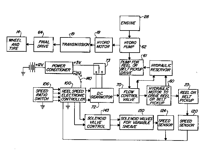
Reel 23 is driven by hydraulic motor 60 which is
fluidically coupled to hydraulic pump 61. As seen in the flow
chart illustrated in FIG. 2, internal combustion engine 28
drives main hydraulic pump 62 which is fluidically coupled to
and drives hydraulic motor 18 which is operatively coupled to
transmission 19. The transmission in turn is operatively
coupled to final drive assembly 64 which is used to drive
wheels 14.
Pump 61 is driven by the header drive assembly, 80 that
the pump is driven only when the header is being operated.
Fluid from pump ~1 is directed to flow control valve 70 before
being directed to motor 60. Flow control valve 70 is a
metering valve whose metering is controlled by a permanent
magnet D.C. gear motor 72. The gear motor can be driven in
both the forward and reverse directions by reversing the
polarity of the electric energy directed to the motor.
The operator is provided with a manual control switch 73
for electrically controlling the gear motor and in turn the
position of the flow control valve. Switch 73 is a neutral
return switch 80 that when it is released by the operator, it
returns to neutral position electrically decoupling motor 72
from a source of electrical energy. The speed o~ the
hydraulic motor is governed b~ the amount of hydraulic fluid
being directed to motor 60 by valve 70. The operator through
control switch 73 selectively positions the flow control valve
to control the speed of the pickup reel.
Also illustrated in FIG. 2 is solenoid valve control 143
and solenoid valves 150 which are used to control the
positioning of variable sheaves for controlling the speed of
the feederhouse. The driven sheave on the feederhouse drives
the picker units thereby controlling the speed of the corn
head gathering units. The diameter of the variable sheaves i8
adjusted by hydraulic actuators that are hydraulically coupled
to a source of pressurized hydraulic fluid. Solenoid control
valves 150 regulate the flow of hydraulic fluid to the
actuators and thereby the diameter of the variable sheaves.
Automatic Control System
With the present invention, the D.C. gear motor can also
be controlled by reel speed electronic controller 100 which is
provided with reel speed ratio inputs from speed ratio
selector switch 106. The automatic controller comprises a
microcomputer 104, such as Motorola Microcomputer 6805R3,
supplied by the Motorola Corporation of Schaumberg, Illinois.
The microcomputer is provided inputs from the operator who
selects at which speed ratio to drive the reel or picker units
in relation to combine ground speed. The operator input
assembly comprises switch 106 which is electrically coupled
through low pass filters 107, 108, 109 and 110, to ports PC0,
PCl, PC2 and PC3 on the microcomputer. As seen in FIG. 4, the
speed ratio switch comprises a binary coded switch which can
provide up to 16 different outputs (4X4) to the microcomputer.
This binary coded switch can be supplied by Standard Grigsby,
of Aurora, Illinois, Part No. 8714. FIG. 4 also illustrates
the electrical schematic of low pass filter 107 which is
identical for low pass filters 108, 109 and 110.
The microcomputer is also provided with sensor inputs
from various speed sensors mounted on the combine. These
sensors comprise a reel speed sensor 120, a ground speed
sensor 122, and an auxiliary speed sensor 124. All of these
sensor~ may comprise magnetic sensors of the kind marketed by
`:
~J~3J ~
Wabash Magnetics of Wabash, Indiana. The signals ~rom each Or
these sensors is passed through band pass ~ilters 125, 126 and
127 which are provided with a alipper circuit for protecting
the microcomputer. These filters are used to filter out
electromagnetic interference. The specific circuitry o~ band
pass filter 125 and its related clipper circuit is illustrated
in FIG. 5, and is the same for band pass filter~ 126 and 127.
The output of the band pass filters is directed to a
comparator circuit 130 for providing a square wave output to
ports PD6 and INT of the microcomputer. PB2 provides a
control input to transistor Q30. The electrical schematic of
the comparator circuit is also illustrated in FIG. 5.
The comparator circuit comprises three comparators U1, U2
and U3. The inverting input of comparators U1, U2 and U3 is
respectively electrically coupled to reel speed sensor 120,
ground speed sensor 122 and auxiliary speed input 124. The
non-inverting input of each comparator is electrically coupled
to the 2.5 V.D.C. voltage source of the power conditioner.
The output of comparators U1 and U3 are electrically coupled
to port PD6 of the microcomputer, whereas the output of
comparator U2 is applied to the INT input of the
microcomputer. Transistor Q30 is used to ~elect between the
outputs of comparators U1 and U3. More specifically, in
response to a row crop header being mounted to the combine,
auxiliary speed switch 144 is coupled to ground, microcomputer
104 through port PB2 sends a control signal to transistor Q30
grounding the inverting input of either comparator U1 or U3.
In thi6 way, the speed input from the selected harvesting
assembly is always applied to port PD6.
The ground speed sensor 122 is operatively coupled to
transmission 64 for providing a transmission speed signal that
can be used to generate a corresponding ground speed signal.
The reel speed sensor 120 is operatively coupled to reel 23
for providing a reel speed signal, and auxiliary speed input
sensor 124 is operatively coupled to the feederhouse.
The automatic control system is also provided with a
third input source comprising a diagnostic and combine
parameter switche6 132. More specifically, as illustrated in
FIG. 6, switch Sl is used to trigger the diagnostic portion of
.
the software program, switches S2-S4 are used to set the
various operating parameters of the combine and switch S5 i~
held in reserve. More specifically, switches S2-S4 are used
to set the tire size of the combine and the final drive ratio~
to correctly calibrate the microprocessor to the particular
combine configuration 80 that the ground speed is correctly
calculated. The inputs from this input a~sembly are applied
to ports PA2, PA3, PA4, PA5 and PA6 of the microcomputer.
The automatic controller is also provided with a
diagnostic display 134 comprising four LED's as illustrated in
FIG. 6. These LED's can indicate sixteen (4X4) potential
problems by the combination in which they are lit or unlit.
More specifically, a mechanic or technician checking out the
automatic control system would throw switch S1 to trigger the
diagnostics routine of the software program, run the combine
at a specified speed as the DGNSET sub-routine of the software
checks the operating elements. The technician would then
check the diagnostic display, generated by the DIADSP sub-
routine, to see the light combination. The technician or
mechanic would look up this light combination in a service
manual to determine what area of the automatic control system
needed to be checked further.
Ports PBl, PB0, AN0, ANl, VSS, VRL, PAl and PA0 of the
microcomputer are coupled to permanent magnet motor control
circuit 142 for driving permanent magnet DC gear motor 72 to
control the positioning of valve 70. DC gear motor 72 is
electrically coupled to permanent magnet motor control 142 by
jacks Jl-3 and Jl-4. The motor control circuit is better
illustrated in FIG. 7 and essentially comprises four field
effect transistors (FET) Ql, Q2, Q3 and Q4, which are
triggered from the outputs of ports PBl, PB8, PAl and PA0
through four transistor pairs Q5 and Q6, Q7 and Q8, Q9 and
Q10, and Qll and Q12. Each of the transistor pairs are
associated with one of the field effect transistors. More
specifically, field effect transistors Ql and Q4 are used to
drive the DC motor in a first direction, whereas field effect
transistors Q2 and Q3 are used to drive the DC gear motor in
the reverse direction. When Ql is triggered, it provides a
path from the 12 volt DC source to the DC gear motor and Q4 is
,,;.~ 11
, 1 ~C~,
.
i
2005572
simultaneously triggered and provides a path ~rom the DC gear
motor to ground. Similarly, when Q2 i~ triggered it
electrically couples the DC gear motor to the 12 volt source
and Q3 provides a path for electrically coupling the DC gear
motor to ground. In this way, the microcomputer, controls the
direction of the DC gear motor.
The microcomputer senses the electrical potential
supplied to the gear motor through analog input ports AN0 and
ANl~ In this way, if the gear motor is being manually driven
by the operator through manual control switch 73, the
microcomputer will not drive the motor and will wait until the
operator is no longer driving the gear motor and switch 73 has
returned to neutral. In addition to detecting if an operator
is controlling the motor, ports AN0 and ANl also detect if the
power supply lines to the motor have become shorted. If a
short is detected, the microcomputer will not drive the motor
until the short is corrected.
The DC gear motor itself comprises a permanent magnet
motor. The motor should be provided with a limit switch such
as is available from Riverside Electronics of Lewiston,
Minnesota. The limit switch stops the motor at zero and 180
rotation to prevent damage to the valve by the motor.
As described above, the present invention can be used to
drive a reel or pickup belt on a harvesting platform, but it
should be noted, that it can also be used to drive a row crop
header and/or a corn head. This auxiliary system is triggered
by assembly switch 144. Switch 144 is actuated by
electrically coupling port PB7 of the microcomputer to ground
through a suitable electric coupling. Switch 144 can be
incorporated into the mechanical mounting assembly of the row
crop and/or corn head so that as the row crop head is mounted,
port PD7 is coupled to ground.
The auxiliary speed input sensor would be located on the
feederhouse and would operate in a manner similar to the reel
speed sensor in that it would direct an input signal through
the band pass filter 127 to comparator circuit 130 and to the
microcomputer. The microcomputer would provide an output
signal through ports PA7, PB7 and PC5 to the solenoid valve
control circuitry 143, which is illustrated in FIG. 7. The
.
.
'
solenoid valve control clrcuit comprise~ two relay~ 146 and
148 for triggering two solenoid valves. The relays are
triggered by transistors Q20 and Q22 and are used to control
two valve coils 152 and 154. The microcomputer, through port
PC5, controls the energization of solenoid 154. When solenoid
152 is energized, the speed of the front end equipment i8
decreased. However, energizing both solenoids increases
equipment speed. The solenoid valves 150 are used to adjust
the effective diameter of variable sheaves which are used to
drive the feederhouse and the row and/or corn head.
The microcomputer, through port PC4, is electrically
coupled to the header lift switch 140. In response to the
header being lifted, switch 140 signals the microcomputer,
which in turn stops solenoid valves 150 from opening. This
prevents overloading of the hydraulic pump that supplies both
hydraulic fluid to the header lift circuit and solenoid valves
150 .
It should be noted that the present automatic control
system senses both ground speed and the eventual output speed
of the harvesting assembly. It then, through the software and
in response to the input of the operator ratio select or
switch, adjusts the speed of the harvest assembly as a desired
ratio of ground speed. As discussed above, the harvester
assembly can be a reel, a pickup belt, a row crop header
and/or a corn head. The software for accomplishing these
tasks which is programmed into the ROM of the microcomputer
will be discussed below.
Software
The software stored in the microcomputer is illustrated
in simplified flow charts illustrated in FIGS. 8 - 12. The
source code of the computer program is disclosed in the
microfiche appendix filed together with this application.
The automatic control system is actuated by starting the
combine and switchi~g switch 106 to the desired ground speed
ratio. To begin with, at step 200, the computer initializes
the outputs by clearing the microcomputer RAM and starts
sen~ing the various inputs. Next, at step 202, the
microcomputer interrogates switch Sl of the diagnostics and
combine parameter switch 132. If this switch is actuated, the
:
.
.~
automatic control system runs the diagnostic routine; if this
switch is not actuated, the program proceeds to the REEL or
PICKER routine control decision at step 204. At step 204, the
microcomputer interrogates assembly switch 144. If this
switch is actuated, the microcomputer proceeds with the PICKER
routine, if this switch is not actuated, the microcomputer
proceeds with the REEL routine.
REEL Routine
In REEL, the microprocessor initially detects, at step
206 the selected speed ratio set by the operator at switch
106. At step 208, the microcomputer detects the ground speed
signal received from sensor 122 and calculates the ground
speed based on the combine parameters set in switches S2-S4.
At step 210, the microcomputer senses reel speed based on the
reel speed signal received from sensor 120. From these
inputs, at step 212, the microcomputer calculates the desired
reel speed as being ground speed multiplied by the speed input
; ratio. Based on the calculated desired reel speed, the
microcomputer from a lookup table stored therein, sets up gain
change points A-J, at step 214. The curve illustrated in FIG.
13 is a graphical presentation of the gain change points A-J
and represents the path by which the microcomputer will
accelerate or decelerate the reel to reach the desired speed.
The microcomputer then calculates the error signal, at
step 216, by subtracting the desired reel speed from the
actual reel speed. Depending on whether the error signal is
positive, negative, or equal, as determined at step 218,
determines whether FETS Q1 and Q4, or Q2 and Q3 are triggered
by the microcomputer. At steps 220 and 222, the microcomputer
calculates the electrical signal to be directed to the gear
motor. This signal is determined by multiplying the absolute
value of the error signal by the gain as determined in FIG.
13. Therefore, the required electrical signal can be
calculated from the vertical axis of FIG. 13.
Before the motor command signal can be applied to the
motor, the microcomputer, at step 224, checks the electric
signal at analog input ports AN0 and AN1 to check if the motor
is being manually controlled or has short circuited. If the
motor is okay, the output control signal is directed to the
14
3 l ~
motor, at step 228, for drivlng the valve. If the motor has
shorted or i9 being manually controlled, the outputs ~rom AN0
and AN1 are turned off at step 226. ~he microcomputer then
returns to the beginning of the program at MAIN and
continually updates the process.
The curve illustrated in FIG. 13 is stored in a lookup
table stored in the memory of the microcomputer. However,
this curve can also be generated from a polynomial equation to
provide a continuously changing response pattern. However,
for simplicity purposes, the lookup table generated curve was
selected which is linear between adjacent gain set points.
Ths principal feature of the curve is that the overall curve
is non-linear and that the greater the error in absolute
terms, the greater the signal response. In this way, the
control system more rapidly is driven to a zero error
condition in which the reel is being driven at the correct
speed ratio. A dead band is provided on either side of the
zero error condition to provide an acceptable range of error
conditions in which the reel speed will not have to be
adjusted.
It may be desired that the curves located on either side
of the dead band illustrated in FIG. 13 not be of the same
slope. This is because it is easier to slow down the reel,
because of its inherent drag, than to speed up the reel.
Therefore, the gain slope for accelerating the reel may be
steeper than the gain slope for decelerating the reel.
PICKER Routine
If switch 144 is coupled to ground, the PICKER routine is
initiated. The microcomputer is directed to read the picker
speed and the ground speed at step 250. At step 251, the
microcomputer detects the selected speed ratio at switch 106.
Next, it is determined whether the ground speed or picker
speed are in the correct control range, at steps 252 and 254,
respectively. If they are not, diagnostic flags are set at
steps 256 and 258, which will be referred to when discussing
the diagnostic routine.
After determining i~ the ground speed and picker speed
are in the control range, it is necessary at step 260 to
calculate the desired picker speed from the speed ratio input
L !
:: . ...
of switch 106 and the ground speed. The desired picker ~peed
is calculated by multiplying the selected ratio by the actual
ground speed. In step 260, after the desired picker speed i8
calculated, a dead band range i8 calculated on either side of
the zero error condition to provide an acceptable range o~
error conditions in which the picker speed wlll not have to be
adjusted. After the dead band is calculated, the error is
calculated, at step 262, by subtracting the actual picker
speed from the desired picker speed.
The calculated error is then compared to the positive
dead band limit, at step 264, and the negative dead band
limit, at step 266, to determine if the solenoid valves need
to be adjusted. If the calculated error falls within the dead
band, the solenoid valves are not adjusted. However, at step
268, if the error is greater than the positive dead band, the
valves are adjusted to increase the speed of the driver.
Similarly, at step 270 if the error is less than the negative
dead band, the solenoid valves are adjusted to change the
diameter of the variable sheaves and to decrease the speed of
the driver. After adjustments are made to the solenoid or it
has been decided not to adjust the solenoid valve at step 272,
the program returns to the beginning of the program at MAIN to
continually update the process.
Diagnostic Routine (~GNSET/DIADSP)
If switch S1 of the switch 132 is closed, a diagnostic
program better illustrated in FIGS. 11, 12a and 12b is run to
determine if the control system is functioning correctly.
The maintenance technician initially switches switch Sl
of the diagnostic and combine parameter switch to an ON
position and then starts the combine. The operator checks to
see that switch 106 is switched to an OFF position and
proceeds to drive the combine at a predetermined speed
outlined in the maintenance manual. At this point, the
operator then switches switch 106 to a CHECK position. In the
initial OFF position, all the switches in switch 106 are open.
At step 300 the microcomputer checks to see if each of these
switches are open. If one or more of the switches are closed
during this OFF sequence diagnostic flags are set at step 301.
16
.. . .
At step 302, the microcomputer checks to see lf DGNSET is
finished exercising the gathering units. If DGNSET is
finished, the microcomputer proceeds to the DIADSP ~ub-
routine, if DGNSET is not finished, the microcomputer proceeds
to step 304. At step 304, the microcomputer checks to
determine if switch 106 is in the CHECK position. If switch
106 is in the CHECK position, the microcomputer proceeds to
step 306, if switch 106 i5 not in the check position, the
microcomputer proceeds to the DIADSP sub-routine. It should
be noted that if no diagnostic flags are erected at step 301,
the DIADSP sub-routine would cycle the microcomputer back to
the beginning of DGNSET. If, however, flags were set up at
step 301, these flags would be displayed by the DIADSP sub-
routine.
Returning to step 306, this step checks to see if the
gathering units are being exercised by the DGNSET sub~routine.
If they are being exercised, the microcomputer proceeds to
step 310, if they are not being exercised, the microcomputer
is directed to step 308 which turns off the gathering units.
As above, assembly switch 144 identifies which harvesting
assembly is mounted to the combine. At step 310, the
microcomputer interrogates switch 144 to determine if the
exercise routine for the reel should be performed, at step
312, or the exercise routine for the picker should be
performed, at step 314. Steps 312 and 314 are provided with
steps for flagging problem areas during the exercise routine,
comprising steps 313 and 315, respectively. It should also be
noted that the PICKER routine also includes diagnostic
flagging at steps 256 and 258. The REEL routine does not
include these diagnostic flagging steps and relies on step 312
to identify diagnostic flags.
The automatic diagnostic exercising cycle comprises
increasing the speed of the reel or picker for a fixed period
of time, then holding that speed for a fixed period of time
and then decreasing the speed for a similar specified period
of time.
At steps 316 and 318, the microcomputer checks to see if
the exercising of the gathering units has been completed. If
it has not, the exercise routine is cycled through either the
.,. ~ , .
... .
i
,....................................................... .
,: .
~j~u~
REEL or PICKER routines by CHKTYP. Essentially, stops 312 and
314 call up specified gathering unit speed-to-ground epeed
ratios, that are stored in memory. These speed ratios are
processed by the REEL and PICKER routines in exerci~ing the
gathering units. In this way, the normal control routines,
REEL and PICXER, are used to control the exercising of the
gathering units.
After the diagnostic test sub-routine DGNSET has been
completed, the diagnostic display sub-routine DIADSP is
started. The picker or reel drive are turned off at stQp 320
and the program now prioritizes and displays the diagnostic
flags identified in DGNSET. In prioritizing and displaying
the diagnostic flags, the microcomputer first determines if
any diagnostic flags have been set at step 322. If flags have
been set, step 324 clears the NTF (no trouble found) flag; if
no diagnostic flags have been set, step 326 sets the NTF flag.
After setting or clearing the NTF flag, the microcomputer
proceeds to the next step, which is setting timers. The
microcomputer, at step 328, sets the timers for two seconds.
At step 330, the microcomputer checks if the display
LED's 134 are on. If the display LED's are on, the program
checks the various diagnostic flags at steps 332, 334, 336,
338, 340, 342, 344 and 346. If the LED's are off, the program
determines if two seconds have elapsed at step 348. At steps
350 and 352, if the display LED's are turned off for two
seconds, they are turned back on. At steps 350 and 354, if
the display LED's are turned on for two seconds, they are
turned off. After the LED's are turned back on, the program
can evaluate the diagnostic flags set in the DGNSET sub-
routine, in evaluation steps 332-346. In displaying
diagnostic information, the LED's flash the various diagnostic
codes on and off for two seconds. The two second off period
between adjacent display codes helps set off the adjacent
codes for easier operator review.
The program is set up to evaluate the various diagnostic
flags in a set order or priority. The specific diagnostic
flag being checked is determined by the current diagnostic
code number. The diagnostic code is a four digit binary
number that begins at 0000 (0) and ends at diagnostic code
~" 18
. .
,..~
;, :
. ;~ .
'
~3 ~ 2
1110 (14). The diagnostic code i8 increased at step 356 by
one each time the flags are evaluated. More specifically~
each time a flag is checked and is not set; or each time the
flag is checked, set and the diagnostic code displayed; the
diagnostic code is increased by one to checX the next flag in
the diagnostic code sequence.
Steps 334 and 346, 336 and 344, and 338 and 342 are
paired to form diagnostic display decisions. The first step
in each pair is the determination of the current diagnostic
code number. As this number increases by one, through each
iteration, this number continually changes and in effect
prioritizes the sequencing of the display decisions. The
second step in each pair is tied to a particular diagnostic
flag.
For example, step 346 determines if there was no ground
speed recorded during the diagnostic testing. If this
determination is yes, the diagnostic code of 0001 is displayed
on the LED's by step 358. If ground speed was recorded, the
microcomputer would proceed to step 356 where the diagnostic
code would be increased by one to 0010 (2). Step 360 then
checks the diagnostic code to determine if its 0000 (0) and if
it is not, recycles the microcomputer to reset the timers.
Steps 332 and 334 are then interrogated again regarding the
diagnostic code until reaching step 336. As the diagnostic
code is 0010, step 336 directs the microcomputer to step 344
which determines whether the ground speed was out of
acceptable range. Step 344 then either recycles the
microcomputer through steps 356 and 360 or displays the
diagnostic code at step 358.
The microcomputer proceeds through eleven more diagnostic
display decisions, corresponding to diagnostic codes 0011 (3)
to 1101 (13) which are not shown. These codes and the
illustrated diagnostic display decision are listed in Table 1.
Diagnostic code 1110 (14) is checked at step 338. If this
diagnostic code i6 detected, the microcomputer is directed to
step 342. If this code is not detected, the microcomputer is
directed to step 340. Step 342 determines if the NTF (no
trouble found) flag was set in step 326. If the NTF flag was
set, the microcomputer is directed to step 358 which directs
19
, .
~ w ~
diagnostic display 134 to display diagnostic code 1110. If
the NTF flag was not set, the microcomputer i8 directed to
step 356 which increases the d~agnostic code by one. From
there, step 360 recycles the microcomputer to the beginning to
reset the timers. As the diagnostic code is now 1111 (0),
step 340 directs the microcomputer to step 358 which displays
the end of display flag.
It should be noted that FIG. 11 only illustrates a
truncated version of the program. More specifically, the
diagnostic code steps and the related flag evaluation
decisions are listed in Table 1. These diagnostic steps are
prioritized into a defined order. The maintenance technician
fixes the problem area associated with each diagnostic flag in
the defined order. As the technician solves the first flagged
problem area and reruns DGNSET to check his or her fix, some
of the later flagged problem areas may disappear as they were
associated with the fix.
Table 1
Diagnostic Code Flag Evaluated
OooO (o) Start/end diagnostic code
(Steps 332 & 360)
0001 (1) No ground speed
(Steps 334 & 346)
0010 (2) Ground speed out of range
(Steps 336 & 344)
0011 (3) No gathering unit
0100 (4) Gathering unit speed out of
range
0101 (5) Ratio switch 106 bit 1
0110 (6) Ratio switch 106 bit 2
0111 (7) Ratio switch 106 bit 4
1000 (8) Ratio switch 106 bit 8
1001 (9) Jl-3 shorted
1010 (10) J1-4 shorted
1011 (11) Gathering unit speed will
not increase
1100 (12) Gathering unit speed will
not decrease
1101 (13) Unused flag set
~; ~ 20
~tlJ.~l~
1110 (14) No trouble flag
(Step~ 338 & 342)
1111 (15) End of display sequence
(Step 340)
The evaluation part of this program starts with the
diagnostic code being 0000 at step 332. It also ends with the
diagnostic code being 0000 at step 360. If the diagnostic
code is 0000 at step 360, the microcomputer is returned to the
start of the DGNSET sub-routine.
The above-described invention provided an automatic
control system for controlling the speed of gathering units
for harvesting assemblies. The system is easy to use and can
be used with a variety of harvesting assemblies.
21
'~,t~