Note: Descriptions are shown in the official language in which they were submitted.
200~as
-- 1 --
The present invention relates to a magnetic flux
measuring method and apparatus for embodying the same,
which are adaptable for, for example, a leakage flux flaw
detection.
A method for detecting a flaw of a steel pipe, a steel
plate, etc., may come in three varieties, an ultrasonic
flaw detecting method, an eddy current flaw detecting
method, and a leakage flux flaw detecting method. Of those
methods, the leakage flux flaw detecting method is
relatively widely used, because it can detect flaws in both
sides of a thick steel plate from a single side, and it has
a high sensitivity in detecting flaws in the innards of a
steel pipe.
In a typical known technique of the leakage flux flaw
detecting method, a DC power source supplies DC power to a
coil wound around a magnetizing yoke. A test piece to be
detected is put on the magnetizing yoke and is magnetized
there. If the detected test piece contains a flaw,
magnetic flux partially leaks outside of the test piece
from the flaw. A magnetic flux sensor detects the leakage
flux and converts it into an electrical signal. In this
way, the flaw is detected in an indirect manner. The
leakage flux emanating from the flaw is very weak and the
sensitivity of the magnetic flux sensors now marketed is
very small.
Further, the initial bias voltages of the sensors are
greatly different from one another. Therefore, before use,
the initial bias voltage must be adjusted for each sensor;
200~609
-
otherwise when the detected signal is amplified, the
amplifier using a sensor having a low initial bias voltage
is saturated, and consequently the flaw detector is
inoperable for flaw detection.
Moreover, the temperature characteristic, that is to
say the rate of change of the output voltage of the known
sensors against temperature is great.
Accordingly, an object of the present invention is to
provide a magnetic flux measuring method and apparatus for
embodying the same which are sensitive to a minute magnetic
field, but insensitive to temperature variation.
According to one aspect of the present invention,
there is provided a magnetic measuring method comprising
the steps of: supplying an AC current of predetermined
frequency to a coil wound around a ferromagnetic core
through a fixed impedance means; and performing a magnetic
flux measurement in terms of a level of a DC component of a
voltage generated across the coil.
According to another aspect of the present invention,
there is provided a magnetic flux measuring apparatus
comprising: a series connection circuit of a coil whose
core is made of ferromagnetic material, and a fixed
impedance means connected serially to the coil; a power
source for supplying an AC current of predetermined
frequency to the series connection circuit; and a detecting
means for detecting a DC component of a voltage generated
across the coil; whereby a magnetic flux measurement being
performed in terms of a level of a DC component detected by
_ - 3 - 20056~
the detecting means.
According to still another aspect of the present
invention, the magnetic flux measuring apparatus further
comprises a level discriminating circuit with such a
hysteresis characteristic that when a voltage waveform
generated across the coil reaches a preset positive
reference voltage, the level discriminating circuit
produces a signal of a high level, and when the voltage
waveform reaches a preset negative reference voltage, the
circuit produces a signal of a low level. A magnetic flux
measurement is performed in terms of a pulse width of a
voltage signal outputted from the level discriminating
circuit.
According to still another aspect of the present
invention, the fixed impedance means is replaced with the
coil whose core is made of ferromagnetic material in the
above inventions.
According to still another aspect of the present
invention, there is provided a magnetic flux measuring
method comprising the steps of; supplying a pulse current
with a DC bias component to a coil wound around a
ferromagnetic core through a fixed impedance means; and
performing a magnetic flux measurement in terms of a level
of a DC component contained in a voltage generated across
the coil.
According to yet another aspect of the present
invention, there is provided a magnetic flux measuring
apparatus comprising: a series connection circuit of a
2005609
- 4
coil whose core is made of ferromagnetic material and a
fixed impedance means; an oscillator for supplying a pulse
current to the series connection circuit; a bias adding
means for adding together a pulse current fed from the
oscillator to the series connection circuit and a DC bias
component; a detecting means for detecting a DC component
contained in a voltage generated across the coil; and a
magnetic flux measurement being performed in terms of a
level of a DC component detected by the detecting means.
The magnetic flux measuring apparatus further
comprises control means for comparing a level of a DC
component detected by the detecting means with a preset
reference voltage, and for controlling a DC bias component,
which is added by the bias adding means, in accordance with
a difference voltage obtained by the comparison.
This invention can be more fully understood from the
following detailed description when taken in conjunction
with the accompanying drawings, in which:
Fig. 1 shows an explanatory diagram for explaining a
conventional leakage flux flaw detecting method;
Fig. 2 is a graph showing relationships between
leakage flux density vs. distance between the surface of a
steel material detected and a Hall device in Fig. 1;
Fig. 3 is a perspective view showing a steel material
with a flaw used in Fig. 2;
Fig. 4 is a graph showing relationships between
magnetic flux density and an output voltage of the various
conventional sensor;
- S - 200~S0~
Fig. 5 is a graph showing a variation of initial bias
voltages of magneto-resistive devices;
Fig. 6 is a circuit diagram showing a measuring
circuit for measuring an output voltage vs. temperature
characteristic of a conventional magneto-diode;
Fig. 7 is a graph showing an output voltage vs.
temperature characteristic of the conventional magneto-
diode as measured by using the circuit of Fig. 6;
Fig. 8 is a circuit diagram for explaining the
principles of the present invention;
Fig. 9A shows waveform of an output voltage of an
oscillator in the circuit of Fig. 8;
Figs. 9B and 9C show waveforms of the voltages across
a coil in the circuit of Fig. 8;
Figs. lOA and lOB show a hysteresis characteristic and
a magnetic permeability characteristic of a ferro-magnetic
core used in Fig. 8;
Figs. llA through llD show waveforms of the voltages
outputted from the oscillator and across the coil, which
are useful in explaining an additional principle of the
present invention;
Fig. 12 is a circuit diagram showing an embodiment of
the present invention;
Fig. 13 is a graph showing a magnetic flux density vs.
output voltage characteristic (detecting sensitivity
characteristic) of the embodiment of Fig. 12;
.~~
~~ - 6 - 200~60-9
Fig. 14 is a graph showing a variation of a voltage
across the coil against a resistance variation;
Fig. 15 is a graph showing a variation of a bias
voltage of the coil against a variation of an output
voltage of the oscillator;
Fig. 16 is a graph showing a variation of a bias
voltage of the coil against a resistance variation;
Fig. 17 is a circuit diagram showing another
embodiment of the present invention;
Fig. 18 is a circuit diagram showing yet another
embodiment of the present invention;
Fig. 19 is a graph showing a magnetic flux density vs.
output voltage characteristic (detecting sensitivity
characteristic) of the embodiment of Fig. 18;
Fig. 20 is a circuit diagram showing still another
embodiment of the present invention;
Fig. 21 shows an explanatory diagram for explaining a
magnetic flux measuring apparatus;
Fig. 22 is a graph showing a relationship of an output
voltage vs. magnetizing current of the apparatus of Fig.
21;
Fig. 23 is a diagram showing a diagram useful in
explaining an additional principle of the present
invention;
Fig. 24 is a block diagram showing a circuit of the
apparatus of Fig. 23;
_- _ 7 - 200~6~
Figs. 25A to 25C show waveforms showing a
characteristic of the circuit of Fig. 24;
Fig. 26 is a circuit diagram showing another
embodiment of the present invention;
Fig. 27 is a graph showing a relationship of an output
voltage vs. magnetizing current of the circuit of Fig. 26;
and
Fig. 28 is a circuit diagram showing an additional
embodiment of the present invention.
A typical known technique of the leakage flux flaw
detecting method will first be described with reference to
Figs. 1 to 7. A shown in Fig. 1, a DC power source 3
supplies a DC power to a coil 2 wound around a magnetizing
yoke 1. A test piece 4 to be detected is put on the
magnetizing yoke 1 and is magnetized there. If the
detected test piece 4 contains a flaw 5, a magnetic flux
partially leaks outside of the test piece 4 from the flaw
5, as indicated by dotted lines. A magnetic flux sensor 6
detects the leakage flux and converts it into an electrical
signal. In this way, the flaw 5 is detected in an indirect
manner. The leakage flux emanating from the flaw 5 is very
weak as shown in Fig. 2, which graphically illustrate
relationships between the leakage flux and a distance
between the surface of a steel material and Hall device as
the magnetic flux sensor. Fig. 3 shows a steel material to
be used for a measurement in Fig. 2. In the figure, W
indicates the width of the flaw and "d", the depth of the
- 8 - 2~0~60~
flaw.
A sensitivity of the known magnetic flux sensor,
however, is very small as shown in Fig. 4. In the figure,
a line "a" indicates a sensitivity of a magneto-diode as a
magnetic flux sensor; a line "b", that of a magneto-
resistive sensor; a line "c", that of a Hall device.
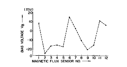
A variation of the initial bias voltages of twelve
magneto-resistive flux sensors is as shown in Fig. 5. As
seen from the graph, the initial bias voltages of the
sensors are greatly different from one another. Therefore,
before use, the initial bias voltage must be adjusted for
each sensor; otherwise when the detected signal is
amplified, the amplifier using a sensor having a low
initial bias voltage is saturated, and consequently the
flaw detector is inoperable for flaw detection.
A temperature characteristic of a magneto-diode 7 is
plotted as shown in Fig. 7, when it is measured by using a
circuit in which a magneto-diode 7 is connected through a
resistor 8 to a DC power source 9, as shown in Fig. 6. As
seen, the rate of change of an output voltage of the sensor
against temperature is great.
The principles of the present invention will now be
described. As shown in Fig. 8, an oscillator 11 as a power
source at predetermined frequency and voltage is connected
in series to a fixed impedance 12 and a coil 14 wound
around a ferromagnetic core 13. In the series connection
circuit, when the oscillator 11 supplies an AC power of a
waveform as shown in Fig. 9A to the coil 14. A voltage
9 290.~609
generated across the coil 14 depends on a resistive value R
of the fixed impedance 12 and an impedance Zs of the coil
14, as given by
eO = e Zs/(R + Zs)
where eO = voltage across the coil 14, and
e = output voltage of the oscillator 11.
An impedance of the coil 14 varies in proportion to a
magnetic permeability of the core 13 because it is wound
around the core 13. Let us consider that an AC current is
fed to the coil 14 in a state that a magnet 15 for
producing an external magnetic field is separated from the
core 13, that is, no external magnetic field is applied to
the core 13. At this time, a magnetic permeability of the
core 13 varies as shown in Fig. lOB due to its hysteresis
property shown in Fig. lOA. In the figure, "n" is the
number of turns of the coil, and "i" is a coil current.
Accordingly an output voltage generated across the
coil 14 varies as shown in Fig. 9B. As seen, under a
condition that no external magnetic field is applied, a
waveform of the voltage across the coil is symmetrical with
respect to the zero level, and a positive peak value vl of
the voltage across the coil is equal to a negative peak
value v2.
When the magnet lS is made close to the coil 14 as
indicated by a dotted line in Fig. 8, the magnetic flux
passing through the core 13 is the sum of the flux
generated by the coil 13 and the flux by the external
magnetic field. Accordingly, a voltage generated across
.,
2~0~609
-- 10 --
the coil 14 takes a waveform as shown in Fig. 9C and vl >
v2.
This fact shows that an external magnetic field can
indirectly be detected in a manner that the positive value
V1 and negative value V2 of the voltage across the coil 14
are compared, and a difference between them is obtained.
If this is applied to the leakage flux flaw detecting
method, a flaw can be detected because a leakage flux is
generated by a flaw.
The present invention is based on the principle as
mentioned above. A magnetic flux measurement is performed
by supplying an AC power at predetermined frequency and
voltage to a coil wound around a ferromagnetic core through
a fixed impedance means, and by detecting a level of a DC
component of a voltage generated across said coil.
When considering a waveform of the voltage generated
across the coil 14 from another view, the times ~ and ~T
during when voltage levels reach fixed reference voltages
ER and -ER respectively become ~T = 2r, as shown in Fig.
llA, in a situation that no external magnetic field is
applied. When external magnetic field is applied, the
times r and ~T during when voltage levels reach fixed
reference voltages ER and -ER respectively become ~12T ~ 2~,
as shown in Fig. llC.
Accordingly, an external magnetic field can be
measured in a manner that, as shown in Figs. llB and llD, a
waveform of the voltage generated across the coil is
converted into a voltage signal of a fixed amplitude by a
- 11 200~60~
level discriminating circuit with reference voltages ER and
-ER~ such as a comparator having a hysteresis
characteristic, and times rl and r2 during when the voltage
level change from ER to -ER and from -ER to ER respectively
are measured in terms of a pulse width of the converted
voltage signal, and the measurement results are used.
A preferred form of the invention is based on the
above principle. According to such preferred form, for the
magnetic flux measurement, a level discriminating circuit
produces a voltage signal in accordance with a waveform of
the voltage generated across the coil, and a pulse width of
the voltage signal is detected.
In a further preferred form, the fixed impedance means
is replaced with a second coil whose core is made of
ferromagnetic material. The impedance of the two coils
vary in response to an external magnetic field whose
magnetic flux crosses the coils. A connection point
between those coils provides a voltage proportional to a
difference between the magnetic field intensities of the
coils. Accordingly, a magnetic flux measurement is
possible by appropriately processing the voltage by using a
DC component detecting means and a pulse width modulating
means.
Temperature variation influences the winding
resistance of the coil and the permeability of the
ferromagnetic core, although the influence is a little. A
variation of the impedance of the coil due to the
temperature variation causes the magnetizing current to
~q 2005609
- 12 -
equally vary in the positive and negative swings.
Accordingly, the variations are cancelled out to each
other, causing no drift of the output voltage due to the
temperature variation. When the magnetizing current
flowing through the coil is increased till the
ferromagnetic core is saturated, the output voltage across
the coil is clipped at a fixed value. The positive and
negative amplitudes and the phase of the voltage across the
coil are varied by only the magnitude of the external
magnetic field. This indicates that the detection
sensitivity is insensitive to the variations of the output
voltage of the power source and the resistance of the fixed
impedance means if the variations are within a tolerable
range.
Preferred forms of the present invention improve a
measuring span of the magnetic flux sensor. Where no flaw
is contained in the test piece to be detected, a leakage
flux essentially occurs. In such preferred forms, the
pulse current superposed by a DC bias component is fed to
the magnetic flux sensor. If the leakage flux crosses the
sensor, it can be cancelled within the sensor.
A further preferred form of the invention may vary a
DC bias voltage in accordance with a level of the leakage
flux, by varying the DC bias voltage applied to the sensor
in accordance with a level of a DC component of the voltage
across the coil.
There will now be described an embodiment of this
invention with reference to the accompanying drawings.
,
~_ - 13 - 2~05609
As shown in Fig. 12, an oscillator 21 at predetermined
frequency and voltage is coupled with a series connection
circuit of a resistor 22 as a fixed impedance means and a
coil wound around a ferromagnetic core 23. A voltage eO
generated across the coil 24 is applied to a positive
voltage detector 25 and a negative voltage detector 26.
The output voltages of these detectors 25 and 26 are
applied to an adder 27, which produces an output voltage
Vo. In this embodiment, an AC current is fed from the
oscillator 21 to core 23 through the resistor 22, till the
core 23 is saturated.
The voltage across the coil 24 is detected by the
detectors 25 and 26. The detector 25 produces a DC voltage
V1 which is proportional to a positive voltage vl of the
voltage eo. The detector 26 produces a DC voltage V2 which
is proportional to a positive voltage v2 of the voltage eo.
The DC voltages V1 and V2 are applied to the adder 27,
where V1 + (-V2) is calculated. The adder produces an
output voltage Vo. Where no external magnetic field is
applied to the core 23, ¦ V1 ¦ = I V2 ¦ and hence the
output voltage Vo is O V. Where an external magnetic
200~;609
- 14 -
field is applied to the core 23, the DC voltages Vl and
v2 vary in accordance with the polarity and the inten-
sity of the external magnetic field. Accordingly, the
output voltage vo of the adder 27, Vo = Vl + (-V2),
depends on the external magnetic field. Therefore, a
minute magnetic flux coupled with the coil 24 can be
measured in terms of the output voltage Vo.
The magnetic flux measuring system of the present
embodiment was used and the result of the measurement
is as shown in Fig. 13. For a minute magnetic flux
variation of 0 to 10 gauss, the output voltage vo varied
in a broad range of 0 to about 500 mv. This shows
remarkable improvement of the sensitivity. In Fig. 13,
a line "a" indicates a sensitivity of a magneto-diode
as a magnetic flux sensor; a line "b", that of a
magneto-resistive device; a line "c", that of a Hall
device. These a, b and c correspond to those of
Fig. 2.
If this measuring system is applied to the leakage
flux flaw detecting method for detecting flaws of a
steel pipe, a steel plate and the like, the flaw detec-
tion can be made with a high precision.
In another measurement of the measuring system of
the present embodiment, the output voltage eo of the
oscillator 21 was 30Vpp (peak to peak voltage), the
magnetic flux density was fixed at 10 gauss, and the
resistance Rl of the resistor 22 was varied at 50, 100,
2005609
- 15 -
150, and 200 ohms. The output voltages eo obtained were
plotted as shown in Fig. 14. While the resistance of
the resistor 22 is changed 0 to four times, the output
voltage eo varies about 0.5v to 0.2v. A sensitivity
difference for the minute magnetic field intensity was
approximately 60%. If a metal coated resistor is used
for the resistor 22, its resistance change is 1% or less
for temperature variation of 0 to 80C. Practically,
the detecting sensitivity is not changed by the tempera-
ture variation.
A further measurement was conducted in a condition
that resistance Rl of the resistor 22 was 100 ohms,
and the output voltage eo of the oscillator 21 was
varied between 20 and 30vpp. In the measurement,
variation of a bias voltage VB of the coil 24 was
measured and the result as shown in Fig. 15 was
obtained. That is, a maximum of variation of the bias
voltage VB was 0.17V. When considering the fact that a
variation of the output voltage eo of the oscillator 21
is usually below 1%, influence of the variation of the
bias voltage upon the magnetic flux measurement can be
negligible.
In an additional measurement, the output voltage of
the oscillator 21 was set at 30Vpp and the resistance Rl
of the resistor 22 was changed to 50, 100, 150 and 200
ohms, and thus the bias voltage VB of the coil 24 was
measured. The result of the measurement is shown in
Z005609
- 16 -
Fig. 16. The variation of the bias voltage VB was O.lV.
Since the temperature variation of the practical resis-
tor 22 is below 0.1%, a variation of the drift voltage
against the temperature variation can be negligible.
Another embodiment of the present invention will be
described with reference to the accompanying drawings.
Like reference symbols are used for designating like
portions in the previous embodiment.
In the second embodiment, as shown in Fig. 17, an
output voltage eo across the coil 24 is compared by the
comparator 28, to amplify a difference between positive
and negative voltages Vl and V2. The output signal of
the comparator is passed through a low-pass filter 29,
and then is outputted as an output voltage Vo. Also, in
this embodiment, the external magnetic field can be pro-
duced in terms of a voltage of a difference between the
positive voltage Vl and the negative voltage V2 of the
output voltage eo across the coil 24. The advantageous
effects as those of the previous embodiment can be
obtained.
A still another embodiment of the present invention
will be described. As shown in Fig. 18, the output
voltage eo across the coil 24 is applied to a comparator
31 as a level discriminating circuit. The comparator 31
is made up of an operational amplifier 32, and resistors
33 and 34. The voltage eo is applied to the inverting
input terminal (-) of the amplifier 32. The resistor
2005609
17 --
33 iS inserted between the output terminal and the
non-inverting input terminal (+) of the operational
amplifier 32. The resistor 34 is connected between the
non-inverting input terminal (+) and the ground. The
5 output signal of the comparator 31 is applied to a low-
pass filter 35, and is outputted as an output voltage
vo .
In the present embodiment based on the pulse width
modulation system, the output voltage eo across the coil
10 24 iS applied to the inverting input terminal (-) of the
amplifier 32. The output signal Eo of the amplifier 32
is divided by the resistors 33 and 34, and is positively
fed back to the non-inverting input terminal (+) of the
amplifier 32.
A ratio of the resistances R2 and R3 of the
resistors 33 and 34 is selected so as to satisfy the
following relation.
- ¦ ER ¦ = ¦ EP ¦
= ¦ Eo ¦ X R3/(R2 + R3)~
20 where ¦ ER ¦ = reference voltage
¦ EP ¦ = positive feedback voltage.
Since the output voltage of the comparator 31 is a
positive and negative voltages, the reference voltages
ER and -ER as shown in Fig. llA or llC are automatically
25 applied to the non-inverting input terminal (+) of
the amplifier 32. Accordingly, the comparator 31
has a hysteresis characteristic. With such
2005609
- 18 -
a characteristic, the comparator 31 produces an output
signal as shown in Fig. llB or llD when the external
magnetic field is absent or present. The output voltage
is the pulse width modulated voltage. The output
voltage thus produced is passed through the low-pass
filter 35, so that the DC output voltage Vo can be
derived depending on a ratio (~ 2) of the pulse
widths ~1 and l2 Therefore, the minute magnetic flux
leaked to the outside can be measured by the output
voltage Vo.
By using the measuring apparatus as mentioned
above, a high output voltage vo of 0 to 600mv or more
was obtained for a minute magnetic flux density of 0 to
100 gauss. The measuring apparatus of the embodiment
above showed remarkable improvement of the detecting
sensitivity.
The same advantageous effects are obtained by
the present embodiment as those of the previous
embodiments.
A further embodiment of the present invention is
shown in Fig. 20. A coil 37 wound around a ferromagne-
tic core 36 is used as a second coil instead of the
resistor 22 as a fixed impedance means. Assuming that
the impedances of the coils 24 and 37 are Zsl and Zs2
and the output voltage of the oscillator 21 is "e", the
voltage eo across the coil 24 is
eo = e Zs2/(Zsl + Zs2).
` 20US609
-- 19 --
The impedances Zsl and Zs2 of those coils 24 and 37
vary in accordance with an external magnetic field
coupling with them. Therefore, the output voltage
eo is proportional to a difference between the inten-
sities of the magnetic fields coupled with the coils 24and 37.
As in the previous embodiments, if the output
voltage eo is amplitude detected or pulse width
modulated, only the difference of the magnetic field
intensities can be measured. Thus, the minute magnetic
flux can be measured at a high detecting sensitivity by
the two coils wound around the ferromagnetic cores in
place of the fixed impedance element.
As seen from the foregoing description, the present
lS invention successfully provide a magnetic flux measuring
method and apparatus for embodying the same which are
highly sensitive to a minute magnetic field, but insen-
sitive to temperature variation.
The above approach using the saturable magnetic
flux sensor for the leakage flux flaw detecting method
is advantageous in that the sensitivity for a weak
magnetic field is excellent, but has the following
problems.
As shown in Fig. 21, when a flaw detected piece 123
is magnetized by flowing a DC current to a coil 122 of a
electromagnet 121, the piece provides a closed magnetic
circuit for a magnetic field developed by the magnet
Z005609
- 20 -
121. Accordingly, the magnetic flux passes mainly
through the piece 123. Under this condition, if a
magnetizing force (magnetizing current) is increased,
the magnetic flux partially leaks to the outside of the
piece 123. If a flaw 24 is present in the piece 123, a
magnetic resistance at the flaw 124 increases, and thus
the leakage flux thereat increases. Therefore, the flaw
124 can be detected by measuring a magnetic flux leaked
from the flaw 124 by moving a saturable magnetic flux
sensor 125 as set above the piece 123 in the direction
of arrow.
A measurement was conducted in a condition that
the sensor 125 shown in Fig. 21 was set above over
the entire surface of the piece 123, and a magnetizing
current of 0 to 7A was fed to the coil 122 of the
electromagnet 121. An output voltage of the flux
sensor was measured. The result of the measurement
was as shown in Fig. 22. The graph shows that the
output voltage linearly increases in the range from
0 to 2.7A of the magnetizing current, but when the
magnetizing current exceeds almost 2.7A, the output
voltage is saturated and linearly decreases against the
increase of the magnetizing current. As a result, the
measuring span of the flux sensor is limited to be
narrow. The narrow measuring span possibly degrades the
flaw detection performance in the leakage flux flaw
detection.
2005609
- 21 -
Another embodiment of the present invention, provi-
des a magnetic flux measuring method and apparatus for
embodying the same which expand the measuring span of
the magnetic flux sensor and improves the flaw detection
5 performance in the leakage flux flaw detection using the
saturable magnetic flux sensor.
The principle of this embodiment will first be
described. As shown in Fig. 23, if a DC current is
fed to a coil 122 of a electromagnet 121 to magnetize a
flaw detected piece 123, a magnetic flux partially leaks
from the piece 123 even if the piece 123 has no flaw.
The leakage flux ~ thus links with a magnetic sensor
125, so that it produces an output voltage which varies
as shown in Fig. 22 in response to the magnetizing
15 current. Therefore, a magnet 126 for developing a local
magnetic field is placed close to the magnet 125. The
polarity of the local magnetic field is set to be oppo-
site to that of a magnetic field developed by the coil
122. The intensity of the former is set to be equal to
20 that of the latter. Under this condition, the output
voltage of the magnetic flux sensor is Ov. Accordingly,
the measuring span of the magnetic flux sensor can
apparently be expanded. In this instance, the function
of the magnet 126 is realized by a DC bias voltage added
25 to a pulse current from an oscillator.
As shown in Fig. 24, a high frequency voltage
(pulse current) outputted from an oscillator 131 is
2005609
22 -
applied to an adder 132. A DC power source 133
applies a DC bias voltage to the adder 132. The
adder 132 adds together the high frequency voltage
from the oscillator 131 and the DC bias voltage from
5 the DC power source 133, and applies the composite
signal to a power amplifier 134. The output signal
of the power amplifier 134 is is applied through a
resistor 135 as a fixed impedance to a coil 137 wound
around a ferromagnetic core 136 which constitutes a
magnetic flux sensor.
With such an arrangement, when a DC current
flows through the coil 137 of the magnetic flux
sensor, a DC magnetic field H = NI (AT ) which
depends on the number of turns N of the coil is
15 generated. It is assumed now that the upper side of
the magnetic flux sensor is set to S pole. An external
magnet 138 whose upper side is set to N pole, is moved
in the direction of arrow so that the magnetic field
by the external magnet 138 intersect the magnetic field
by the coil 137. Then, the magnetic field by the magnet
138 mutually repels with that by the magnetic flux
sensor, so that the magnetic flux in the magnetic flux
sensor is cancelled. The supply of the DC current
to the coil 137 of the magnetic flux sensor shifts
25 a hysteresis curve of the core 136 of the magnetic flux
sensor from a location indicated by a solid line to a
location of a dotted line, viz., toward the negative
200S609
- 23 -
side as shown in Fig. 25A. Accordingly, the output
voltage characteristic of the magnetic flux sensor is
changed from that shown in Fig. 25B to that shown in
Fig. 25C. Thus, the use of the DC bias voltage shifts
the characteristic of the magnetic flux sensor toward
the negative side, and hence the operating point to the
same.
An additional embodiment of the present invention
will be described with reference to the accompanying
drawings.
As shown in Fig. 26, a high frequency voltage
(pulse current) is supplied from an oscillator 141 to an
adder 142. A DC power source 143 also applies a DC bias
voltage to the adder 142. The adder 142 adds together
the high frequency voltage from the oscillator 141 and
the DC bias voltage from the DC power source 143, and
supplies the composite signal to a power amplifier 144.
The amplifier 144 amplifies the composite voltage signal
and applies its output to a series connection circuit of
a resistor 145 as a fixed impedance element and a coil
148 of the magnetic flux sensor 146, which is wound
around a ferromagnetic core 147. An output voltage
appearing across the coil 148 is applied to positive and
negative amplitude detectors 149 and 150. The detected
output signals of the detectors 149 and 150 are applied
to an adder 151 where those are added together so as to
output an output voltage vo. The detectors 149 and 150,
2005609
24 -
and the adder 151 make up a DC component detecting
means.
With such an arrangement, the oscillator 141
applies a high frequency voltage to the adder 142. The
5 DC power source 143 also applies a DC bias voltage to
the adder 142. The adder 142 adds the high frequency
voltage and the DC bias voltage together, and applies
the resultant voltage to the power amplifier 144. The
amplifier 144 appropriately amplifies the composite
voltage signal and applies it through the resistor 145
to the magnetic flux sensor 146.
Consequently, an output voltage eo appears
across the coil 148 of the magnetic flux sensor 146.
The voltage eo is detected by the detectors 149 and
150. The positive amplitude detector 149 produces a DC
voltage Vl, which is proportional to a positive voltage
vl of the output voltage eo across the coil 148. The
negative amplitude detector 150 produces a DC voltage
V2, which is proportional to a positive voltage v2 of
the output voltage eo across the coil 148. The DC
voltages Vl and V2 are supplied to the adder 151 where
Vl + (-V2) is computed, and the result of the addition
is outputted as an output voltage Vo.
In a measurement by the measuring apparatus of this
instance, a DC bias current from the DC power source
143 was changed to 0, 50, 100, 150, and 200mA, and the
output voltage of the magnetic flux sensor 146 was
200S609
- 25 -
measured for those magnetizing currents. The results of
the measurement were as shown in Fig. 27. As seen from
the graph, when the DC current of 100 mA is supplied to
the magnetic flux sensor 146, a linear characteristic of
the output voltage of the magnetic flux sensor can be
obtained in the range 0 to almost 4.5 A of the magne-
tizing current in companion with the DC current of 0 mA
and thus a two times measuring span can be realized.
Accordingly, the measuring span can be broadened,
lo improving the flaw detecting performance. When the DC
current is further increased in excess of 100 mA, a
measuring area to measure an intensity of the magnetic
field is shifted while the measuring span remains
unchanged.
An additional embodiment of the present invention
will be described with reference to the accompanying
drawings. Like reference symbols are used for
designating like portions in the previous embodiment.
As shown in Fig. 28, a DC power source 143a,
which can vary a variable DC bias outputted as a DC
power source is provided. An output voltage Vo of
the adder 151 is applied through a low-pass filter 152
to a differential amplifier 153. The differential
amplifier 153 compares the output voltage received
with a reference voltage derived from a reference
voltage generator 154, and applies the difference
voltage to the DC power source 143a. The power source
2005609
- 26 -
143a varies the DC bias in accordance with the voltage
from the differential amplifier lS3. The low-pass
filter 152, the differential amplifier 153, and the
reference voltage generator 154 constitute a control
means for varying the DC bias.
With such an arrangement as shown in Fig. 26,
even if the magnetizing current of the electromagnet,
for example, is fixed, the leakage flux from the no
flaw surface of the piece varies when a contact con-
dition of the electromagnet with the detected piece,the thickness of the piece and the like are changed.
The flaw detecting precision is improved by placing
automatically the operating point at the center, for
example, of the measuring span of the magnetic flux
sensor 146.
In the arrangement of Fig. 28, an operating point
of the magnetic sensor 146 is detected by the output
voltage of the adder 151. A difference voltage between
the output voltage and the reference voltage of the
reference voltage generator 154 is obtained by the dif-
ferential amplifier 153. The DC bias from the DC power
source 143a is controlled by the difference voltage so
that the output voltage Vo of the adder 151 when no flaw
is contained in the piece is automatically compensated
at OV. Accordingly, even if the measuring conditions
change, a satisfactory measuring span is always secured,
further improving the flaw detecting performance.
2005609
- 27 -
As seen from the foregoing, in the leakage flux
flaw detection using the saturable magnetic flux sensor,
the present embodiment is capable of expanding the
measuring span of the magnetic flux sensor, thereby
improving the flaw detecting performance.