Note: Descriptions are shown in the official language in which they were submitted.
200S7~:)3
TONGUE ACTIVATED COMMUNICATIONS CONTROTT.T~'R
Technical Field:
This invention relates to the field of communications
controllers and more particularly to the field of such controllers
which are activated with a user's tongue.
Background Art:
A significant portion of persons who do not have the use of
their limbs are isolated from daily functioning in society. Some
of these persons may have suffered traumatic injuries to their
spinal cord, such as during automobile accidents or sport injuries
and the like; others may have had diseases of the neuromuscular
and central nervous system. In these types of diseases, cognitive
function most often remains intact. It has been found that often
these pathologies do not affect the function of the user's tongue.
The tongue remains accessible as a communications link after all
limb control has been lost, even in such progressive neuromuscular
diseases, such as multiple sclerosis.
The number of such disabled people is increasing in the general
population. Thus, there is an increased need for new devices that
allow the disabled person to work and to have a near-normal
lifestyle. With a faster and more aesthetically acceptable
communications controller, it is possible for the disabled person
20057~
to become a productive part of society. There has been a great
amount of recent development in this area, particularly in the
area of computer controllers for operating mechanical devices.
Current devices exist for hands free computer input. These
devices include a mouth stick controller which is a device
clenched in the user's teeth and operated by gross head motions to
perform various mechanical tasks. This device is utilized
primarily by high level quadriplegics and can be wielded with
adequate proficiency after some practice. However it requires a
high degree of mobility to accomplish specific tasks and is often
awkward to use and leads easily to deteriorization of teeth and
oral occlusion. Additionally, a mouth stick controller has the
limitation that the patient must be in extremely close proximity,
in fact a mouth stick controller extends from the mouth to the
device being operated.
Voice recognition systems are known. However, further
refinement is necessary to produce a reliable method of data
communication even for a person having an unimpaired voice. In
many cases, quadriplegics have partial paralysis of the diaphragm
and larynx. Their speech articulation and volume are severely
hampered. Therefore, voice recognition systems, which require
good articulation and volume, are not well suited to a broad range
of physically impaired persons. Additionally, voice recognition
systems present difficulty in environments where multiple users
coexist.
2~05703
Other devices proposed to assist the disabled person include
many forms of single switch computer control. This type of
control is slow to operate and requires many levels of
programming. Typically, a single switch actuation device requires
an action such as "sip" and "puff" breathing, eyebrow motion, or
chin movements to control or to operate a computer, to actuate an
environmental control or to achieve personal mobility. Disabled
persons with a great degree of mobility and who have a capacity to
operate more than one switch desire increased and faster access to
a computer. Currently, single switch driven software does not
achieve the desired speed that can be obtained by multiple switch
inputs.
Another relevant device is an ultra-sonic head controller. This
device is limited to the user that is able to produce at least
small and precise head movements necessary for keying a computer
via ultra-sonic position detectors. The computer recognizes the
position of the head and deviations in head positions are
interpreted as an analog signal. An example of an ultrasonic
device is the Personics View Control System (VCS), which is
currently commercially available. The Personics system includes
three ultra sonic transducers housed in a headset to receive a
signal transmitted from a control unit. By comparing the signal
received at three points on the headset, changes in the angle and
rotation of the head are tracked.
Yet another device which is designed for persons of limited
mobility is an eye switch apparatus which is an infrared emitter
200~7~3
- 4 -
and detector pair mounted on standard eye-glasses. This
system operates by emitting small, low power, infrared beams.
The reflectivity of the surfaces in front of the emitter can
be sensed. For example, when the eyelid opens or closes, an
electronics unit activates a relay which serves as a switch.
Virtually any body surface can reflect the beam, giving a wide
range of threshold levels and possible methods of operation.
However, there is a distinct lack of speed in the use of such
a device and there is the disadvantage of triggering this type
of device unintentionally, such as during normal eye blinking.
The devices currently known are quite limited in the variety
of devices they can control. Additionally, presently known
devices require physical movements from the disabled user that
may not be possible. What is needed is a device which can be
used by a large number of persons having limited mobility and
which can operate a broad range of devices. The device must
not require difficult physical movements for persons suffering
from progressive neuromuscular disorders and quadriplegia due
to spinal injuries. And, the device should be aesthetically
pleasing.
SU~RY OF THE INVENTION
A tongue activated communications controller is provided
which includes a tongue activated input unit adapted to be
positioned in an oral cavity having a plurality of user
selectable inputs, an encoder connected to the plurality of
user selectable inputs, the encoder producing a first encoded
signal corresponding to the user selectable input activated,
and a transmitting unit including a tuned resonant frequency
2005703
- 5 -
circuit for receiving the first encoded signal as an input and
conveying the first encoded signal through an inductor which
transmits a second, amplitude modified encoded flux field
signal identifying the user selectable input activated.
In one embodiment, the inductor has an inductance of between
about 2.8 and 10 ~H formed by the passage of current through
the inductor. The inductor may be an air core inductor. In
one embodiment, the flux field signal has a frequency of about
2 Mhz. In the controller, the input unit may be a keyboard
having a plurality of tongue depressible keys. The first and
second encoded signals used in the controller may be pulsed
signals and a different pulsed signal may be used for each
user selectable input.
A tongue activated communication controller system is also
provided which includes a mouthpiece. Included in the mouth-
piece is a tongue activated input unit having a plurality of
user selectable inputs, an encoder connected to the plurality
of user selectable inputs, the encoder producing a first
encoded signal corresponding to the user selectable input
activated, and a transmitting unit including a tuned resonant
frequency circuit for receiving the first encoded signal as an
input and conveying the first encoded signal through an
inductor which transmits a second, amplitude modified encoded
flux field signal identifying the user selectable input acti-
vated. The controller system also includes a receiving unit
external to the oral cavity for receiving the flux field
signal and a processing unit for processing the flux field
signal and producing a command signal corresponding to the
2005703
-- 6
user selectable input activated.
The controller and controller system are easily used by
persons having limited physical mobility and are well suited
for use by persons having quadraplegia due to spinal cord
injuries and neuromuscular disorders. The tongue activated
communications controller and controller system enables per-
sons of limited mobility to operate various devices.
Brief Description of the Drawinq:
For a further understanding of the objects and advantages of
the present invention, reference should be made to the follow-
ing detailed description, taken in conjunction with the accom-
panying drawing, in which like parts are given like reference
numerals and wherein:
Fig. 1 is a schematic illustration of the tongue activated
communications controller in accordance with this invention
illustrating usage with a personal computer, a wheelchair as
well as additional applications.
2Q~7~3
Fig. 2 is a partial sectional schematic view of the tongue
activated communications controller in accordance with this
invention installed in the mouth of the user.
Fig. 3 is a perspective view of the assembled tongue activated
communications controller.
Fig. 4 is an exploded perspective view of the tongue activated
communications controller of Fig. 3.
Fig. 5 is an enlarged bottom view of the assembled tongue
activated communications controller illustrating the electrical
circuit of the keypad.
Fig. 6 is an enlarged bottom view of the tongue activated
communications controller of Fig. 3.
Fig. 7 is an enlarged cross-sectional view of the keyboard in
accordance with this invention.
Fig. 8 is an electrical circuit schematic of the tongue
activated communications controller in accordance with this
invention.
Fig. 9 is a side perspective view of a second embodiment of the
tongue activated communications controller in schematic
illustrating a fixed inductor wrapped around the perimeter of a PC
board.
Fig. 10 is an electrical circuit schematic of a second
embodiment of the transmitter circuit of the tongue activated
communications controller in accordance with this invention.
Fig. 11 is a timing diagram illustrating encoded transmission
ZQ05703
from the tongue activated communications controller in accordance
with this invention.
Fig. 12 is a schematic illustration of the encoded signal being
received by the tongue activated communications controller in
accordance with this invention.
Fig. 13 is a flow chart of the software enclosed in the smart
box in accordance with this invention.
Detailed Description of the Invention:
Two embodiments of the tongue activated communications
controller will be described below. It will be appreciated that
many other embodiments are possible within the spirit and scope of
this invention. With particular reference to Fig. 1, there is
shown the overall schematic of the tongue activated communications
controller, in accordance with this invention, generally
designated by the numeral 10. The tongue activated
communications controller 10 (hereinafter TACC) is illustrated as
interfacing with either a personal computer and/or a wheelchair
and/or additional applications. The TACC 10 includes an intra-
oral transmitter assembly 12. The intra-oral transmitter assembly
12 fits into the mouth of a user and is held in place therein by
press fit. It may also be desirable for the intra-oral
transmitter assembly 12 to be held in place in a user's mouth by
clasps as illustrated in phantom in Figs. 3 and 4. After
installation, the user can transmit encoded signals illustrated by
waves 14 to a receiver 16. It is preferable that the
transmission be wireless to increase the flexibility of movement
2~S'7~3
g
of an associated transmitter, however hard-wired embodiments of
the TACC are within the scope of this invention. The signals are
encoded and are transmitted by the TACC in binary form.
The receiver 16 receives the encoded binary signals and
communicates with a smart box 18 which decodes the signals. The
smart box 18 comprises a microcomputer; for example, a Z-80
microprocessor or a 4 bit microcontroller would be suitable. The
smart box 18 decodes the encoded binary signal and determines
which switch on the keyboard has been depressed. The smart box 18
sends a control signal to the desired device for carrying out the
appropriate action, such as inputing to a personal computer or
directing the motion of a wheelchair. The smart box 18 includes
the software for monitoring the received signal and converting it
to the appropriate control signal as will be more fully
appreciated hereinafter.
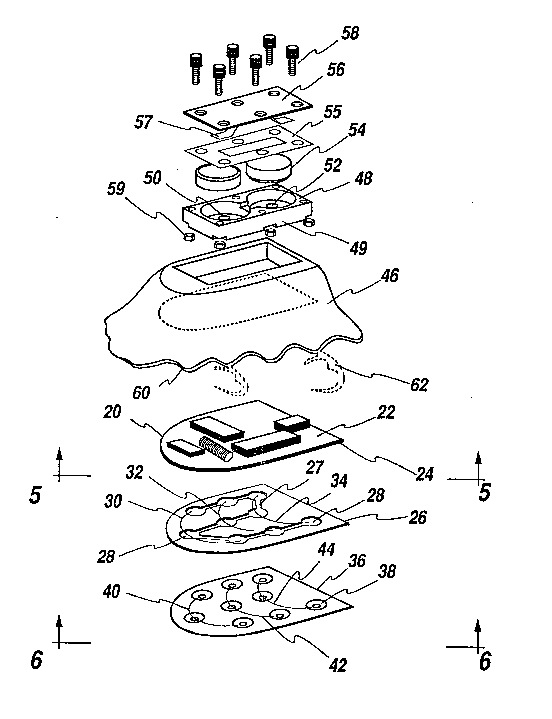
With particular reference to Figs. 2-4, there is shown the
details of the intra-oral transmitter assembly 12. The intra-oral
transmitter assembly 12 includes a PC board 20. The PC board 20
is a two-sided board having a first side 22 with transmitter
electronics and a second side 24 with the electrical circuit for
the keyboard. Thus, the PC board in accordance with this
invention includes both the transmitter electronics and circuitry
for switching from one keyboard position to another.
The first side 22 includes an encoder 96, a transmitter 98, a
timer 100, an oscillator 102, and a voltage regulator 104. A
detailed description of the above elements is set forth below with
200~7~3
--10--
reference to Fig. 8. The particular electrical devices are
preferably low power, high speed semiconductors and are preferably
a combination of CMOS integrated circuits and discrete devices.
These types of semiconductor devices are preferred because they
are compatible with the speed of the 2 MHz crystal oscillator 102.
The intra-oral transmitter assembly further includes an adhesive
spacer 26 having a plurality of openings 28 and a keyboard
membrane 36 including a plurality of conductive key pad members
38. The keyboard membrane 36 is bonded to the PC board 20 using
the adhesive spacer 26. The adhesive spacer 26 is an acrylic
adhesive which creates a water tight seal between the keyboard
membrane 36 and the PC board 20. The adhesive spacer 26 has
channels 27 to permit the movement of air trapped within the
channels 27 and the openings 28 as one of the conductive key pad
members 38 is depressed by the user's tongue.
The adhesive spacer 26 spaces the membrane 36 away from the
second side 24 to prevent short circuiting of the keyboard.
Therefore, the adhesive is made from an insulating material, such
as an acrylic based adhesive. Additionally, the adhesive spacer
26 acts as a moisture barrier to prevent corrosion and
disfunctioning of the electrical circuits. This is especially
important since much of the life of the intra-oral transmitter
assembly 12 is spent in a moist or wet environment.
In the preferred embodiment, there are three rows of openings
28. The rows have an arc shaped design, designated by the lines
having reference numerals 30, 32 and 34 for each of the first,
2005703
--11--
second and third rows, respectively. The arc shaped design
accommodates the conductive key pad members 38. The conductive
key pad members 38 are similarly divided into three rows 40, 42
and 44, designating the first, second and third rows respectively.
As will be appreciated from the more detailed explanation found
with reference to Figure 6, the conductive key pad members 38 are
generally flat and each includes a nipple 92 which protrudes away
from the second side of the PC board. Pressure from the tip of a
user's tongue deforms the pad members 38 and pushes the conductive
surface of the pad members 38 through the opening 28 of the
adhesive spacer 26 and into electrical contact with the second
side 24 of the PC board as best shown in Fig. 7.
The intra-oral transmitter assembly 12 is encapsulated by an
encapsulant 46 made of methyl methacrylate. As shown more clearly
in Figures 2 and 3, the methyl methacrylate encapsulates the PC
board 20 the adhesive spacer 26 and the keyboard membrane 36. The
bottom of the operating surface of the keyboard membrane 36 which
includes the nipples 92 is exposed for access by the user's tongue
and not encapsulated.
The encapsulant 46 has a recess defining a battery compartment
48. Within the compartment 48 are two electrically conductive
pads 50 and 52 which are electrically connected to the voltage
regulator. A pair of batteries 54 are placed in electrical
contact with the pads 50 and 52. In order to protect the user the
batteries 54 are sealed in the battery compartment 48 by a gasket
55 and a cover 56. The cover 56 is placed over the batteries 54
703
-12-
for securing the batteries 54 into electrical contact with the
pads 50 and 52. The cover 56 includes an electrical contact 57
for bridging the two batteries. The cover 56 is secured to the
battery compartment 48 by use of screws 58 and nuts 59 in the
battery compartment.
The cover 56 is made from fiberglass and is mounted almost flush
with the encapsulant 46. In the preferred embodiment, the
encapsulant encapsulates the cover 56. This ensures a comfortable
fit of the intra-oral transmitter assembly 12 to the roof of the
mouth of the user.
The battery compartment 48 has walls 49 made of A-Butyl Styrene.
This provides a double insulation in combination with the
encapsulant to limit any passage of fluids or gases between the
inside of the battery compartment 48 and the user's mouth.
The encapsulant further has teeth interface members 60 which
comprise the shaped outside edges of the encapsulant 46. The
edges are shaped in the form of the profile of the inside of the
teeth and gums in the mouth of the user. In order to accomplish
this, the encapsulant 46 is cast into an impression of the user's
mouth, using standard dental techniques. This allows the intra-
oral transmitter assembly 12 to be press fit to conform to teeth
and gum and the roof of the mouth of the user. Additionally, this
procedure ensures that the fit of the intra-oral transmitter
assembly 12 will be comfortable and secure within the user's
mouth.
2~0~103
-13-
In some mouths, additional security is desirable. As shown in
phantom in Figs. 3 ~ 4, a clasp 62 can be embedded in the
encapsulant 46 and secured to the teeth using standard dental
techniques.
With particular reference to Fig. 5, there is shown the second
side 24 of the PC board 20 having the electrical circuit for the
keyboard. The circuitry is divided into three arc shaped rows 64,
66 and 68. The arc shaped rows 64, 66 and 68 are compatible with
the earlier described first, second and third rows, 30, 32 and 34,
respectively, of the adhesive spacer 26 and the first, second, and
third rows, 40, 42 and 44, respectively, of the keyboard membrane
36. Thus, the conductive key pad members 38 of the keyboard
membrane 36 align with the openings 28 of the adhesive spacer 26
which are aligned with the switches 63.
Each switch 63 is approximately 0.175 inch in diameter. The
switches 63 are divided into three rows. The first row comprises
switches 70, 72 and 74, which are consecutively numbered switches
1, 2 and 3. The second row comprises switches 76, 78 and 80,
which are numbered switches 4, 5, and 6. The third row comprises
numbered switches 82, 84 and 86 which are switches 7, 8 and 9,
respectively.
Each of the switches 63 is generally round in shape. The
center-to-center spacing of adjacent switches is approximately
equal and is approximately 0.3 inch. This is true except for the
center-to-center spacing of switch 2 to switch 5, which is
somewhat larger, approximately 0.37 inch.
7~3
-14-
As can be seen from Fig. 5, each of the switches 63 is
electrically connected by conductive lines 88 and holes 89 in the
PC board 20 to the first side 22 of the PC board 20. Thus, when
an electrical connection is made across the switch 63, a signal
for that switch is sent to the first side 22 keyboard electronics
and transmitted by the intra-oral transmitter assembly 12 to the
receiver 16.
With particular reference to Fig. 6, there is shown the bottom
side of the keyboard membrane 36. The keyboard membrane 36 is
made from mylar and has conductive ink applied to it to create pad
members 38. The conductive ink provides a conductive path across
one of the switches 63 when one of the corresponding pad members
38 is depressed. The adhesive spacer 26 spaces the keyboard
membrane 36 away from the PC board 20 sufficiently (approximately
0.002 inch) so that no electrical contact is made until one of the
pad members 38 is depressed. The channels 27 facilitate the
depression of the pad members 38 by allowing the displacement of
air between the pad members 38 and the PC board 20.
As shown most clearly in Fig. 7, each of the pad members 38 have
a nipple 92. The nipple 92 is in the form of a Braille raised dot
as to both diameter and shape made with a Braille slate stylus.
This provides the user with accurate tactile feedback.
Similar to the switches 63, the pad members 38 are 0.175 inch in
diameter. Adjacent pad members 38 are spaced apart 0.3 inch,
center-to-center. The distance between the middle pad in the
first row 40 and the middle pad in the second row 42, which
20057 03
-15-
corresponds to switches 2 and 5 are somewhat larger than the 0.3
inch center to center spacing and match exactly the spacing of
switches 2 and 5. The nipples 92 are formed so as to facilitate
the detection of one of the pad members 38 with the tongue.
Approximately 0.50 ounce of force is required to depress one of
the pad members 38 to make electrical contact such that a circuit
for switch 63 is completed.
With respect to Fig. 8, there is shown the electrical circuit
schematic for the intra-oral transmitter assembly 12. As shown,
the assembly 12 includes a keypad 94, an encoder 96, a transmitter
98, a timer 100, an oscillator 102 and a voltage regulator 104.
The oscillator 102 preferably oscillates at a fixed frequency of
2MHz.
The keypad 94 comprises the second side 24 switches 1 through 9
as shown in the Fig.8. When one of the switches 63 is closed, an
electrical signal is sent to the encoder 96. The signal received
is encoded using a decade counter 106; for example, if switch 3,
designated by the numeral 74, is closed, an electrical signal is
received at Q4 of the decade counter designated by the numeral
108. This is also pin position 10 of the decade counter 106. The
signal is encoded and sent to an output of the decade counter
designated by Ql and the reference numeral 110. This is also
known as pin position 2 of the decade counter.
The encoded output of the decade counter, Q-l, 110, is sent to
the first NAND gate 112 of the oscillator 102. The encoded signal
2~ J7~3
sent to the first NAND gate 112 is mixed with a carrier signal
created by the oscillator 102.
The oscillator 102 uses a second NAND gate 114, a crystal and
appropriate discrete components to generate a 2 MHz carrier
signal. The carrier signal is then sent through conductive line
116. The carrier signal is then mixed with the encoded signal at
the first NAND gate 112. The output of the mixed signal is sent
to the transmitter 98 over conductive line 118.
The transmitter 98 transmits at 2 MHz frequency using the
carrier signal created by the oscillator 102. In the embodiment
of the transmitter 98 shown in Fig. 8, the transmitter 98 has a
variable inductance and can be adjusted to tune the resonant
frequency of the transmitter 98 to the carrier signal of 2 MHz
The receiver 16 detects the encoded signal from the intra-oral
transmitter assembly 12 and filters out the carrier signal. The
encoded modulated signal, which remains, is passed to the smart
box 18, and decoded to determine which switch on the keyboard has
been depressed. The smart box 18 translates the encoded modulated
signal into a control signal for controlling and operating various
devices, as shown in Fig. 1. The control signal may be analog or
digital in nature. The operation of the receiver 16 and smart box
18 will be more fully appreciated with reference to Figs. 11 - 13.
The frequencies of the various modulating signals transmitted by
the intra-oral transmitter assembly 12 are determined by the timer
100. The voltage regulator 104 reduces the battery voltage
potential of nominally 6V to a potential of 3.3V. This provides
X~05~703
-17-
the power to the semiconductor devices, the decade counter 106 and
NAND gates 111. The 3.3V potential also represents the binary
high for the digital logic. The 3.3V potential is sent over
conductive line 120 to the decade counter enable 122 of the decade
counter 106. This is also known as pin position 14 of the decade
counter 106.
Thus, when the voltage regulator 104 provides the 3.3V signal,
the decade counter 106 is enabled and the clock input 124 is tied
to the timer 100. As can be seen, the clock input 124 is tied to
the output of the timer 100 by conductive line 126 and the voltage
regulator output is tied to the decade counter enable 122 by
conductive line 120. Thus, when the clock is enabled, an encoding
signal corresponding to one of the switches 63, namely the switch
depressed, is sent from the decade counter 106 to the oscillator
102 and then transmitted.
With particular reference to Fig. 9, there is shown a second
embodiment of the intra-oral transmitter assembly generally
denoted by the numeral 130. In the second embodiment, there is a
groove 132 of about .25 inch in depth around the perimeter of the
PC board 20. The wire is wound around the PC board replacing the
variable inductance surface mounted component of the earlier
described embodiment. Magnet wire 133 of 39 gage is tightly wound
around groove 132 and is held in place thereby. Wrapping the
magnet wire 133 creates an inductor having a fixed value, in the
preferred embodiment, the value ranges between 2.8 ~H and 10 ~H.
Unlike the first embodiment the inductance can not be varied after
~)0~;7~)3
-18-
assembly. However, the inductance can be measured on a case by
case basis. The magnet wire 133 is connected to the first side 22
of the PC board in the same location where the variable inductor
was found in the first embodiment 12.
As can be appreciated, a new transmitter circuit, generally
designated by the numeral 135, is necessary to accommodate the
second embodiment of the intra-oral transmitter assembly 130. The
corresponding circuit diagram is shown in detail in Fig. 10. The
transmitter assembly 130 includes a fixed inductor 134 which
comprises the magnetic wire 133 wound around the PC board groove
132, as described earlier. The inductor 134 is a fixed value that
ranges between 2.8 ~H and 10 ~H. The transmitter assembly 130
further includes a pair of 1000 pF capacitors and a tuning
capacitor 136. The tuning capacitor 136 is inserted into the
circuit to assure that the tuned resonant frequency of the
transmitter matches the 2 MHz carrier. The value of the tuning
capacitor 136 is selected accordingly. This ensures the signal is
accurately received by the receiver 16.
When the signal is transmitted, it is done so by a wireless
transmission. If it was desirable for there to be a hard wire
between the intra-oral transmission assembly 12 and the smart box
18, the signal would be tapped directly from the output of the
decade counter 106. In this embodiment no transmitter or
oscillator would be necessary.
Fig. 11 illustrates the encoding of the signal transmitted by
either of the intra-oral transmitter assemblies 12 or 130. The
.. ~, , . . . . . _ _
~)0~5~3
--19--
timer sends out a clock signal represented by pulse line 140.
When none of the switches 63 has been activated, no signal is sent
out from the decade counter 106. This is schematically
represented by a straight pulse line 142. When one of the
switches 63 is depressed a unique pulse line is generated. For
example, when switch 1 has been depressed, a pulse line 144 is
created. Pulse line 144 is a square wave line having a period of
2 T, where T is one timer period. This form of modulation is
called pulse coded modulation.
Coded pulse line 144 is then combined with the 2 MHz carrier and
forms pulse line 145. Pulse line 145 is then transmitted to the
receiver 16 where the carrier is filtered out and the signal
decoded.
When switch 2 is depressed, a pulse line 146 having a period of
3 T (1 T high and 2T low) is created. Pulse line 146 is combined
with the 2 MHz carrier to form pulse line 147 and is then
transmitted to receiver 16. Similarly, when switch 3 is depressed
a 4 T (1 T high and 3 T low) pulse line 148 is created. Again, it
is combined with the carrier and transmitted. The remaining
switches 63 follow the same pattern.
Fig. 12 illustrates receipt of the wireless transmission of the
signal from either of intra-oral transmitter assemblies 12 or 130.
As described above, the receiver filters out the carrier portion
of the signal. The receiver 16 is a modified AM receiver which
has been tuned to the carrier frequency of 2 MHz. This is done by
adjusting the core and changing the capacitors to stabilize the
2QO.S7~3
-20-
reception by minimizing drift. The receiver 16 uses an amplitude
modulation detection scheme to recover the encoded signal.
The receiver 16 sends the demodulated , encoded signal to a
comparator 150 which converts the wave form into binary format.
The comparator 150 sends the signal to a digital filter 152 which
converts the encoded signal into a square wave. The digital
filter 152 sends the resulting, filtered signal to the smart box
18.
The smart box 18 comprises a standard microcomputer
architecture. The preferred embodiment of the smart box includes
a single board computer which has a plurality of input and output
ports, e.g. Prolog, STD-7000 System 7806 Z-80A Multifunction CPU
card 7904 TTL Decoded I/0 Utility Card. The smart box 18, using
the software described in detail below, generates a control signal
for controlling and operating various devices. The control signal
may be digital or analog or a modified digital signal. The
control signal may be altered as needed using the smart box and
the system software.
In order to generate the correct signal, the smart box 18 uses
the system software to determine which switch has been depressed
and activates its own corresponding switch to direct the desired
device to perform the desired function.
The system software referenced above will now be described with
reference to Fig. 13. At the top level of the software, there are
two software loops operating at all times. The main routine is
called TOP, generally designated by the numeral 154. TOP performs
Z~057~3
-21-
initial and preparatory routines and then enters into a repeating
loop. Within this repeating loop the computer executes the MAP-
SWITCH 158 subroutine which selects the mapping of the switch
position identification for different keyboard layouts. Upon
completion of MAP-SWITCH 158, TOP 154 enters another subroutine
called RUN-MODES 160. After executing RUN-MODES 160, the software
checks for keyboard inputs in another subroutine called ?TERMINAL
162. If a key is activated on a programmer's computer, the Main
Event loop within TOP 154 ends. This programmer's computer is
connected to the smart box 18 only during programming and testing.
Otherwise, the Main Event loop repeats, continuing with the MAP-
SWITCH subroutine. The Main Event loop is comprised of MAP-SWITCH
158, RUN-MODES 160 and ?TERMINAL 162. The TOP 154 routine remains
within the RUN MODES 160 as long as one of the pad members 38 is
depressed to cause activation of one of the switches 63.
At regular .512 msec intervals, the computer halts whatever it
is doing in the TOP routine and executes another routine called
TICKER, generally designated by the numeral 164. TICKER 164 is
the interrupt service routine which reads the binary signal from
the receiver 16 and updates the clock variables to reflect the
time between each low to high transition edge of the pulse line as
described with reference to Fig. 11. The TICKER 164 routine
prepares data to be sent out to those devices which require
repeating outputs, for example, a Macintosh computer mouse port.
In other cases, routines within RUN-MODES 160 send out control
information directly without using TICKER 164, for example
2~0^~7C~3
-22-
wheelchair controllers. The TICKER 164 routine calculates the
length of time between successive low to high transition edges and
stores information in the software variables NEW-CLOCK and OLD-
CLOCK. These variables are read into RUN-MODES 160 to determine
which of the switches 63 has been closed.
There are several software subroutines within the smart box 18.
As shown in Fig. 13 there is an initialization subroutine called
INITS, designated by the reference numeral 156, which performs the
functions of initializing variables, and configuring the timers in
the smart box 18 necessary for the interrupt service routine.
INITS 156 also performs a one time initialization of variables
handled regularly within the interrupt service routine, TICKER
164, and establishes the location of TICKER 164 in memory. The
TICKER 164 routine runs whenever its interrupt is encountered and
handles all timing calculations.
Additionally, INITS 156 performs the functions of preparing the
variables used in identifying each switch 63, configuring the
variables that control the acceleration behavior of a device such
as a computer mouse and configuring the motorized wheelchair
controller so that the wheelchair is stationary upon initial
operation.
The MAP-SWITCH 158 contains a simple one to one table which
changes the logical identity associated with each switch so that
the switches 1 through 9 can be mapped anywhere on the keypad.
The RUN-MODES 160 selects one of the available operation modes
which the smart box 18 operates. For example, the modes in the
2Q057Q~
-23-
smart box 18 are ?TEST, MOUSE or CHAIR . ?TEST configures the
operation of the intra-oral transmitter assembly 12 into a test
mode; MOUSE converts operation of the intra-oral keypad into a
Macintosh mouse emulation; and CHAIR converts the operation of the
intra-oral keypad into the directional control of a powered
wheelchair. Other additional operational modes can be added as
required and then the smart box will behave in one of these modes
as desired.
In the CHAIR mode, the user depresses one of the conductive key
pad members 38 to control a motorized wheelchair. In a preferred
embodiment a DUFCO controller is used and the CHAIR subroutine
produces the output necessary to operate such a controller. The
user can move one of 8 directions; forward, forward right, right,
...or send a stop signal.
The CHAIR mode includes a lower level subroutine entitled, TACC-
KEY? which examines the switch closure data from either one of the
transmitter assemblies 12 or 130 to determine which switch if any,
has been closed. There are several error suppression algorithms
within the TACC-KEY? subroutine to minimize the effect of key
bounce and transmission signal degradation.
The CHAIR mode includes another lower level subroutine entitled,
RUN-CHAIR, which reads which switch the user has closed and
performs a table look-up to determine which bits (binary values)
to set high or low in the output signal. This output signal is
composed of a four bit word: a forward bit, a reverse bit, a left
bit and finally a right bit. These bits determine the direction
- 2005703
- 24 -
that the wheelchair moves. All acceleration and velocity
ramping is handling by the DUFCO wheelchair controller hard-
ware. These bits form a command instruction for the wheel-
chair controller and when outputted, the wheelchair controller
responds with movement.
An additional low level CHAIR subroutine is entitled, STOP-
CHAIR which sets the four bit signal sent to the DUFCO wheel-
chair controller to zero. This instructs the wheelchair to
stop.
The mouse mode includes low level routines which translate
switch closure into Macintosh mouse emulation.
While the foregoing detailed description has described
several embodiments of the tongue activated communications
controller in accordance with this invention, it is to be
understood that the above description is illustrative only and
not limiting of the disclosed invention. Particularly, any
number of devices, including environmental controls,
computers, telephone, musical instruments and other devices
could be operated by the tongue actlvated communications con-
troller in accordance with this invention. It will be ap-
preciated that all such embodiments are within the scope and
spirit of this invention. Thus, the invention is to be
limited only by the claims as set forth below.