Language selection

Search

Patent 2005789 Summary

Third-party information liability

Some of the information on this Web page has been provided by external sources. The Government of Canada is not responsible for the accuracy, reliability or currency of the information supplied by external sources. Users wishing to rely upon this information should consult directly with the source of the information. Content provided by external sources is not subject to official languages, privacy and accessibility requirements.

Claims and Abstract availability

Any discrepancies in the text and image of the Claims and Abstract are due to differing posting times. Text of the Claims and Abstract are posted:

  • At the time the application is open to public inspection;
  • At the time of issue of the patent (grant).
(12) Patent: (11) CA 2005789
(54) English Title: SPARK-PRODUCING MECHANISM FOR WHEEL ASSEMBLY
(54) French Title: MECANISME A MOLETTES POUR BRIQUETS
Status: Expired and beyond the Period of Reversal
Bibliographic Data
(51) International Patent Classification (IPC):
  • A63C 17/26 (2006.01)
  • A63H 17/26 (2006.01)
(72) Inventors :
  • YEH, CHENG-SIUNG (Taiwan, Province of China)
(73) Owners :
  • LUCKY STAR ENTERPRISE & CO., LTD.
(71) Applicants :
  • LUCKY STAR ENTERPRISE & CO., LTD. (Taiwan, Province of China)
(74) Agent: KIRBY EADES GALE BAKER
(74) Associate agent:
(45) Issued: 1993-10-26
(22) Filed Date: 1989-12-18
(41) Open to Public Inspection: 1991-06-18
Examination requested: 1989-12-18
Availability of licence: N/A
Dedicated to the Public: N/A
(25) Language of filing: English

Patent Cooperation Treaty (PCT): No

(30) Application Priority Data: None

Abstracts

English Abstract


TITLE OF THE INVENTION:
SPARK-PRODUCING MECHANISM FOR WHEEL ASSEMBLY
ABSTRACT OF THE DISCLOSURE
A spark-producing mechanism for wheel assembly
comprises a plurality of flints, a fixing ring for the
mounting of flints which closely fits to the shaft of
the wheel, a grindstone which is inserted in the
interior of the wheel. By rotating the wheel, the
flints rub against the grindstone to produce sparks.


Claims

Note: Claims are shown in the official language in which they were submitted.

-5-
Claims:
1. A spark-producing mechanism for wheel assembly comprising a wheel, bearings, a
fixing ring, a plurality of springs, a plurality of flints, a compression ring and a
grindstone, characterized in that said fixing ring for the mounting of said flints closely
fits to the shaft of the wheel in a suitable position; said compression ring is fitted on
the outer ring of said fixing ring, said flints come into contact with said grindstone
being inserted in the interior of the wheel via the compression ring.
2. A spark-producing mechanism for a wheel assembly comprising:
a first bearing including a bushing portion fitted to a shaft having a threaded
end;
a second bearing including a bushing portion fitted to said shaft adjacent said
first bearing;
a wheel having a central portion and annular lip depending therefrom, said
central portion serving to engage said first and second bearings;
a fixing ring fitted to the bushing portion of said second bearing, said fixing ring
including a plurality of spaced apart non-through holes on a circumference thereof,
each of said plurality of non-through holes having a spring means and a flint disposed
partially therein, said flint being substantially cylindrical and having a flange proximate
one end thereof, said flint flange serving to support said spring means;
a compression ring mounted on said fixing ring circumference, said compression
ring including a plurality of spaced apart through holes, each of said through holes
being spaced apart in a manner corresponding to the spacing of said fixing ring non-
through holes, whereby said flints may operationally pass therethrough;
a grindstone mounted to an interior surface of said wheel annular lip; and
a nut screwed onto said shaft threaded end, said nut serving to fasten said
wheel in position;
said spring means serving to urge said flints in a radially outward direction into
contact with said grindstone whereby said flints rub against said grindstone to produce
sparks during rotation of said wheel until the flanges of said flints come into contact
with said compression ring.

Description

Note: Descriptions are shown in the official language in which they were submitted.


21D0~ 9
CANADA505KS - 1 -
SPARK-PRO~UCING MECHANISM FOR WHEEL ASSEMB~Y
BACKGROUND OF THE INVENTION
This invention pertains to a spark-producing
mechanism fo~ wheel assembly, comprising a plurality of
flints and a fixing ring for the mounting of the flints
which closely fits to the shaft of a wheel. The flints
come into contact with a grindstone which is inserted
in the interior of the wheel. By rotating the wheel,
the flints rub against the grindstone to produce
sparks.
Conventional wheel assembly such as the skateboard
comprises four wheels, a set of frame, and a board. A
skateboarder must consciously use the skateboard and
skate in combination. The skateboarder can thereby
move forward, turn and stop as desired. However,
conventional wheel assembly only provides the rotating
of wheel as its sole purpose.
SUMMARY OF THE INVENTION
It is therefore a primary object of the present
invention to provide a spark-producing mechanism for
wheel assembly which utilizes the friction between the
flints and the grindstone to produce sparks when the
wheel is rotated.
A further object of the present invention is to
provide a spark-producing mechanism for wheel assembly
which is easily assembled and disassembled because of
its simple structure.
~W

2005789
-2-
Another object of the present invention is to pro~de a spark-producing
mechanism for wheel assembly by which the sparks produced are absolutely safe.
These, and other objects and advantages of the present invention, will become
more apparent from a consideration of the following detailed description of the
preferred embodiments, when read in conjunction with the accompanying drawings.
According tc the invention there is provided a spark-producing mechanism for
wheel assembly comprising a wheel, bearings, a fixing ring, a plurality of springs, a
plurality of flints, a compression ring and a grindstone, characterized in that said fixing
ring for the mounting of said flints closely fits to the shaft of the wheel in a suitable
position; said compression ring is fitted on the outer ring of said fixing ring, said aints
come into contact with said grindstone being inserted in the interior of the wheel via
the compression ring.
BRIEF DESCRIPTION OF THE DRAWINGS
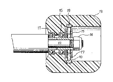
lS FIG. 1 is a cross-sectional view of a spark-producing mechanism in accordance
with the subject of the present invention;
FIG. 2 is an exploded view illustrating component parts of the present
invention; and
FIG. 3 is an embodiment of the present invention in use.
DETAIL~3D DESCRIPTION OF THE PREFERRED EMBODIMENT
Referring now to PIGS 1 and 2, an exemplary preferred embodiment of a
spark-producing mechanism for wheel assembly of the present invention is illustrated
in which a bearing (11) (its bushing has one side outwardly extended) closely fits to
one extreme end of the shaft (12) of the wheel and comes into contact with the
extension of the shaft (12) thereto, said shaft (12) haYing both ends threaded. A
wheel (13) having a recess on one lateral side at the central part thereof is compactly
combined with the bearing (11). A second bearing (16) also closely fits the shaft (12)
of the wheel and touches the bearing (11) by means of its outwardly extending
bushing. Both extensions of the
A

~)0~ 9
CANADA505KS ~ 3 -
bearing bushing are joined together to form a circular
zone. The wheel (13) has a inner flange so as to fit
the circular zone to keep the bearings in a fixed
location. There is a clearance between the flange and
the beaxing bushing to prevent them from touching each
other. Another recess is provided opposite to the
central part of the wheel (13). The bearing (16) is
mounted within the wheel (13) with both ends of the
bearing bushing extending outwardly and providing
enough extension to make a fixing ring (15) fit closely
thereto. The extended bushing of the bearing (16)
closely fits the fixing ring (15) by being inserted
through the inner hole of the same. There are a
plurality of holes (23) and threaded holes (24) along
the circumference of the fixing ring (15). Preferably,
these holes are provided symmetrically. Each of the
hole ~23) contains a flint (10) and a spring (22). The
flint (10) is substantially cylindrical and has a
flange near to the bottom thereof for supporting the
spring (22). A compression ring (17), providing
circumferentially a plurality of holes (25,26) with
equal number corresponding to the fixing ring (15), is
fitted on the outer rim of the fixing ring (15). The
compression ring (17) and the fixing ring (15) are
fastened to each other by a plurality of screws (27)
via the holes (26). A grindstone (19), which is a
circular ring, is inserted in the interior of the wheel
(13) during the fabrication procedure and is adjusted
in order to come into contact with the projecting flint
(10). By means of rotating the wheel (13), the flint
(10) rubs against the grindstone (19) to produce
sparks. After abrasion, the flint ~10) is pushed
outward by means of the restoring force of the
compression spring (22). The flint (10) can produce

2~)05~9
CANADA505KS - 4 -
sparks continuously by means of rotating the wheel (13)
until the flange of the flint (10) comes into contact
with the inner wall of the compression ring (17). The
outside of the wheel (13) forms a concave part in the
center for easy assembly and disassembly. A nut (14)
screws onto the screw end of the shaft (12) of the
wheel to fasten the wheel (13) into position.
FIG. 3 is an embodiment showing a skateboarder
using a skateboard.
While the invention has been described with a
certain degree of particularity, it is manifest that
many changes may be made in the details of construction
and the arrangement of components without departing
from the spirit and scope of this disclosure. It is
understood that the invention is not limited to the
exemplified embodiment set forth herein but is to be
limited only by the scope of the attached claims,
including the full range of equivalency to which each
element thereof is entitled.

Representative Drawing
A single figure which represents the drawing illustrating the invention.
Administrative Status

2024-08-01:As part of the Next Generation Patents (NGP) transition, the Canadian Patents Database (CPD) now contains a more detailed Event History, which replicates the Event Log of our new back-office solution.

Please note that "Inactive:" events refers to events no longer in use in our new back-office solution.

For a clearer understanding of the status of the application/patent presented on this page, the site Disclaimer , as well as the definitions for Patent , Event History , Maintenance Fee  and Payment History  should be consulted.

Event History

Description Date
Time Limit for Reversal Expired 1998-12-18
Letter Sent 1997-12-18
Grant by Issuance 1993-10-26
Application Published (Open to Public Inspection) 1991-06-18
All Requirements for Examination Determined Compliant 1989-12-18
Request for Examination Requirements Determined Compliant 1989-12-18

Abandonment History

There is no abandonment history.

Owners on Record

Note: Records showing the ownership history in alphabetical order.

Current Owners on Record
LUCKY STAR ENTERPRISE & CO., LTD.
Past Owners on Record
CHENG-SIUNG YEH
Past Owners that do not appear in the "Owners on Record" listing will appear in other documentation within the application.
Documents

To view selected files, please enter reCAPTCHA code :


To view images, click a link in the Document Description column. To download the documents, select one or more checkboxes in the first column and then click the "Download Selected in PDF format (Zip Archive)" or the "Download Selected as Single PDF" button.

List of published and non-published patent-specific documents on the CPD .

If you have any difficulty accessing content, you can call the Client Service Centre at 1-866-997-1936 or send them an e-mail at CIPO Client Service Centre.


Document
Description 
Date
(yyyy-mm-dd) 
Number of pages   Size of Image (KB) 
Abstract 1994-07-15 1 12
Drawings 1994-07-15 3 67
Description 1994-07-15 4 125
Claims 1994-07-15 1 40
Representative drawing 1998-06-17 1 13
Maintenance Fee Notice 1998-01-28 1 179
Fees 1996-11-06 1 52
Fees 1995-11-08 1 51
Fees 1994-11-30 1 37
Fees 1993-09-19 1 57
Fees 1992-11-11 1 37
Fees 1991-11-24 1 37
PCT Correspondence 1993-08-10 1 50
Courtesy - Office Letter 1990-06-07 1 18
Prosecution correspondence 1993-01-19 1 45
Examiner Requisition 1992-09-27 1 60