Note: Descriptions are shown in the official language in which they were submitted.
20060 22
RELATED APPLICATIONS
Canadian Patent No. 1,300,575 and the following
related Canadian patent applications refer to subject matter related
to the subject matter of this application:
Application Serial No. 2006018, filed December 19, 1989
Application Serial No. 2006019, filed December 19, 1989
Application Serial No. 2006023, filed December 19, 1989
Application Serial No. 2006024, filed December 19, 1989
Application Serial No. 2006025, filed December 19, 1989
Application Serial No. 2006026, filed December 19, 1989
Application Serial No. 2006027, filed December 19, 1989
FIELD OF INVENTION
This invention relates to document collating and
envelope stuffing machines, and in particular to an automatic
machine of the foregoing type capable of higher speeds and increased
reliability and flexibility.
BACKGROUND OF THE INVENTION
U.S. Patent No. 4,169,341 describes an automatic
document collating and envelope stuffing machine comprising a main
flow
_,_
sg/lcd _
20060 22
path employing a continuous conveying mechanism to an envelope
stuffing station, in which one or more feeding stations deposit
documents onto a platform associated with each feeding station.
The documents in each platform are picked up seriatim by the con-
veying mechanism and subsequently stuffed into envelopes. The
feeding stations are each in parallel with the main conveying
mechanism, which operates continuously to pick up whatever docu-
ments are present on each feeder platform.
While this machine operates satisfactorily for its in-
tended purpose, it does have certain inadequacies which limit its
flexibility and speed. For example, the speed is determined
solely by the main conveying mechanism, which proceeds at the
same velocity even though documents are not present on the plat-
forms. Moreover, it is difficult to keep track of the collation
contents from station to station. Still further, it is dif-
ficult, if not impossible, to employ a single address document
with coding to indicate the collation contents which can control
each of the feeding stations in turn.
Particularly, it is difficult to establish a communica-
tion protocol between modules in a modular insertion system which
will permit maximum speed of operation while not restricting the
manner in which modules inter-communicate. This is an important
aspect for features such as queuing, pass collations, rejecting
erroneous collations, passing error messages recognizing and ad-
ding new modules without the requirements of changing switches or
-2-
2006022 ~:~
re-programming memory, and mufti-language capability for non-
English language countries.
DESCRIPTION OF THE PRIOR ART
The patents to Tomlinson et al 4,564,901 and Ward
4,636,947 each relate to parallel processing systems utilizing
concurrent data transfer, the former specifically directed to
asynchronously intercoupled microprocessors.
Prodel et al (4,646,245) and Ropelato (4,771,374) relate
to modular manufacturing and process controls; Stiffler et al
(4,608,631 and 4,484,273) teach modular computer systems per se;
Crabtree et al (4,604,690) provides for dynamic reconfiguring of
a data processing system for added devices; and Shah et al
(4,589,063) and Vincent et al (4,562,535) disclose automatic con-
figuration in single computer systems.
The patent to Davis et al (4,354,229) shows a loop in-
itialization process.
The patent to Innes (4,615,002 and 4,595,908) relates to
the multilingual features.
SUMMARY OF INVENTION
An object of the invention is a document collating and
envelope stuffing machine that can operate at high speeds.
A further object of the invention is a document collating
and envelope stuffing machine that provides complete control of
the collation contents.
Another object of the invention is a document collating
and envelope stuffing machine that is more flexible in its opera-
-3-
~oooo~~
tion, by which is meant that the machine can control the contents
of each collation by programming each feeder station, or by
providing an address document coded with the collation contents
which controls each feeder, or by an operator manually instruct-
s ing each feeder station of the documents it is to contribute to
the collation.
These and other objects and advantages as will appear
hereinafter are achieved with a novel document collating and en-
velope stuffing apparatus characterized by a plurality of local
0 feeding stations with each located in series in the main document
flow path. Each local feeding station is provided with a local
queuing station directly in the main flow path. Each feeding
station, in turn, captures the global collation created by the
previous upstream feeding stations, adds if desired one or more
documents to the collation, and then passes on to the next
downstream station the resultant global collation. A computer
record is kept of the global collation, and as documents are
added the computer record is updated and passed on to the next
feeding station. The basic system may be called on-demand feed-
ing. Each local feeding station in turn notifies the next local
feeding station when its collation is complete so that the next
feeding station is prepared to accept and contribute its own
documents if desired to the global collation. The last feeding
station, on demand, then feeds the resultant global collation to
the envelope stuffing station, which can be followed if desired
023.002.PIT-273(C-452) -4-
2UUUU~~
by a flap moistening and sealing station and ultimately by a
sorter or postage machine if desired. In accordance with another
feature of the invention, the accumulated collation record is
checked for completeness, and if incomplete, the stuffed envelope
is ejected from the main flow path.
This invention is also directed to a material processing
system comprising a plurality of material processing stations, a
base material processing station, and means directing material to
be processed serially through the plurality of stations in a
given order to the base station; the improvement wherein each of
the plurality of stations and the base station comprises a sepa-
rate data and control processor, and further comprising a commu-
nication loop interconnecting the processors of the plurality of
stations in the given order to the processor of the base station
and interconnecting the processor of the base station to the pro-
cessor of the first of the plurality of stations; the processors
of the plurality of stations comprising means responsive to a
determined signal from the processor of the base station to the
processor of the next succeeding station of the identification
data that the respective station has assigned to itself, whereby
the processor of the base station receives data from the last of
the plurality of stations corresponding to the number of the
plurality of stations connected to the communication loop.
Principal benefits derivable from the machine of the in-
vention include:
023.002.PIT-273(C-452) -5-
20060 22
1) the ability to add on additional feeding stations as
modules without changing the basic operation. These additional
feeding stations can include sheet feeders. bursters~ which separate indi-
vidual sheets from perforated fan-folded continuous paper,
folders and like document handling apparatus;
2) the speed of the machine is not fixed, but is instead
dependent primarily on the time required for each local contribu-
tion to the collation. Thus, if no local contribution is made,
no unnecessary delays are encountered at that feeding station;
3) the collation record which is passed on from station
to station is kept up to date and provides a reliable record of
the collation contents at every station in the machine.
4) the up-to-date collation record can readily be used
to control subsequent machine operations, such as ejection in
case of a defective collation;
5) if an address document is used, it retains its posi-
tion on top of the collation stack and thus can be readily
scanned to control the machine, and, when the global collation is
stuffed in the enveloped, the address on the address document can
be readily positioned to be visible through a window in the en-
velope.
The system employs asynchronous operation with no
reciprocating motion. Previous inserter systems have operated
asynchronously, but they have used a ram type reciprocating oper-
ation for insertion. This organization and structure reduces the
-6-
2006022
vibration and noise and allows a lighter machine to be constructed.
The queuing station arrangement and queuing device accumulates and
holds documents in collation order until a downstream module calls
for the collation to be transferred. If a jam is encountered in one
station, jam clearing becomes much quicker because it is not
necessary to disturb other collations in different module queuing
stations, as all the other queue stations are in the wait state.
The user only has to clear one station. A two belt system is
employed for positive drive of collation through the insertion
station. Positive high speed control is obtained by a continuous
belt insertion drive mechanism. The continuous belt insertion
provides a new form of insertion not previously used. Prior art
devices use a large wheel with a small roller which has to be
operated synchronously. The use of the same device for both
conveying a collation and also inserting it into an envelope is
unique. After insertion, the envelope is turned 90 degrees and sent
to the next module for moistening and postage application. The
device also provides for asynchronously operating the envelope
turner in relation to the inserter operation. The asynchronous
relationship between the envelope turner and the inserter allows the
inserter to reject erroneous collations without having to operate
the turner and other downstream equipment. The electronic control
of the present invention uses a unique communication arrangement
which combines command/response and peer to peer communications.
When the system is on but not running in insert mode, the
communication is a command/response, master/slave communication
sg/lcd
2ooso 22
arrangement. This is a one-to-one command/response protocol where
the master, the base envelope feeder microprocessor, retains command
and control over the various inserter module microprocessors.
However, while the system is running in insert mode, the
communication technique changes to a peer to peer or module to
module transfer mode wherein each module creates a record of its
activity, known as a piece record, and passes it onto the next
module. Master/slave communication is precluded during this mode
of operation. Normal communications between modules during insert
mode (not during, for example, a jam requiring user intervention)
are transparent to the user. This allows the use of a single UART
for dual purpose communications. It allows the throughput of large
volumes of information because the processing is in parallel in each
module and the data transfer throughout the modules is concurrent.
The system also allows for automatic configuration of
equipment on power up, and generates (each time it powers up) the
necessary operating configuration information of the equipment.
Prior systems require a configuration PROM installed in the
equipment. For each configuration change, a new configuration PROM
had to be generated and physically changed. It should be noted
that such equipment allowed the user to select features within the
configuration, but not to change the configuration itself.
The ring of topology of the present invention
facilitates geographic addressing for module identification. The
sys-
-g_
sg/lcd
_w
2UUUU~~
tem employs a master controller operating in conjunction with the
module computer. The system configuration analysis command from
the master controller during the power up sequence requires each
module in the inserter to send data back. Because of this ar-
rangement, the base system will have stored therein the number of
modules and their respective addresses. The base need not know
the particular nature of the modules. This allows for the addi-
tion of new and as yet unknown modules to the system. The soft-
ware architecture is such that all messaging is displayed on the
base module (all inserter configurations have an envelope
module). Because all messages that are displayed are generated
by the various inserter modules and transmitted to the base
module microprocessor for display on a display screen (in any
language the operator selects) the system is flexible and allows
the addition of new modules that do not presently exist. This
permits module additions without having to change any of the ex-
fisting software. Modules such as bar code readers, OCR readers,
scanners, sorting devices, etc., can be easily added.
Error messages can also be passed from module to base
unit directly without passing through other modules along the
second channel communication link. Error messages are pre-stored
in each module. The prestoring of error messages also allows the
automatic selection of foreign language error messages.
The electronics in each module allow for generation of a
piece record in software regarding each collation. A piece
023.002.PIT-273(C-452) -9-
200UU22
record is generated by the electronics and is passed from module
to module, without passing through a master controller, asyn-
chronously through the inserter, from one microprocessor to an-
other. The piece record corresponds to the physical collation
which is being moved from module to module. It represents an im-
age of the physical collation. Because of this architecture, one
can pass a large amount of data in block format from module to
module. Modular prior art systems typically worked in a master
slave relations and the concept of direct module to module or
peer to peer communication in this context is unique. The piece
record is a dynamic data structure and accommodates different
sizes of collations in different runs. The piece record is
passed in a sequenced arrangement, module to module, but not
necessarily passed between the modules synchronously with the
physical movement of the documents. Since, the piece record is
dynamic, it can include data for running a printer and/or any
currently unknown or new I/O device.
A preferred embodiment of the invention will now be de-
scribed in greater detail with reference to the accompanying
drawings, wherein:
DESCRIPTION OF THE DRAWINGS
Fig. 1 is a perspective view of one form of apparatus ac-
cordance with the invention;
Fig. 2 is a schematic side of the apparatus of Fig. 1
showing the main document transfer devices and sensors;
023.002.PIT-273(C-452) -10-
2ooso~~
Figs. 3a-3d illustrate schematically the asynchronous op-
oration of the apparatus of Fig. l;
Fig. 4 is an illustration of the reject mechanism of
Fig. 2.
Fig. 5 is a block diagram of the interrelating electron-
ics system for operating the apparatus of Fig. 1;
Fig. 6 is a block diagram of the electronics of a single
module.
Fig. 7 is a block diagram of the electronics of the base
unit.
Fig. 8 is a block diagram of the microprocessor employed
within a single module.
Fig. 9 is a block diagram of the microprocessor employed
within a base unit.
Fig. 10 is a flow chart illustrating the program routine
and system flow within the base unit.
Figs. 11A and 11B are flow charts illustrating the pro-
gram routine and system flow within a module.
Fig. 12 is a continuation of the program routine within
the base unit.
Fig. 13 is a supplemental flow routine.
Fig. 14 is a flow chart illustrating the messaging sub-
routine.
Fig. 15 is a memory map illustrating the translation
routine.
023.002.PIT-273(C-452) -11-
2006022
Fig. 16 is a program routine and system flow chart
illustrating the translation routine.
DESCRIPTION OF THE PREFERRED EMBODIMENT
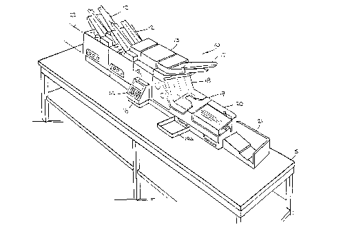
Fig. 1 of the drawings shows a perspective view on a
table 5 of the machine 10 of the invention provided with two
document feeding stations 12, feeding station keyboard for data
entry 12a, a transport station 13, electronics control station 14,
with associated message display screen 15 and data keyboard 16, an
envelope feeding station 17, an envelope stuffing station 18, a
turning and ejection station 19, a moistener and sealing station 20,
and a stacking station 21. Although only two document feeding
stations are shown, it will be appreciated that many more feeding
stations can be added on to the front end of the machine, which has
been indicated by the dashed lines 22 shown at the left end, and the
operation of the overall machine does not change. Such feeding
stations or modules include bursting and folding modules also. The
ability to add additional modules without the necessity of
reconfiguring both mechanisms and the central electronics is an
important feature of the novel machine of the invention. The
keyboard 16 is used to provide operator input as to start, operating
instructions, reset functions and the like. The display 15 is
employed to show error messages, module status, echo keyboard
instructions and the like.
The following detailed description will be more
understandable with the brief description of the underlying concepts
sg/lcd -12-
200G0~~
and operation of the machine now outlined. Each feeding station
is independent of other feeding stations and its operation is
controlled by a local microprocessor. Each feeding station, of
which one or more may be included in the machine, is typically
provided with a hopper for storing a stack of documents, and a
plurality of sensors connected to its local microprocessor for
controlling the feeding of one or more of its documents to the
global collation, and signalling the receipt and departure of the
global collation. Each feeding station contains a queuing sta-
tion for temporarily capturing and holding the global collation.
When the queuing station of the current feeding station
is empty, its local microprocessor is signaled and deposits into
its local queuing station the one or more documents it is in-
structed to contribute. This instruction may come manually from
an operator through the keyboard located on the side of the
feeder, be programmed into the local microprocessor through the
base unit keyboard, or be derived from a coded address document,
typically the top document of the collation, which has been read
by a scanner at an upstream feeding station and the information
passed on to the local feeding station. When the local contribu-
tion is completed, the upstream microprocessor is signaled to
send down the so-far accumulated global collation, which is ac-
complished by opening a gate at the previous queuing station and
activating a feeder mechanism which then deposits the global col-
lation on top of the local contribution at the current queuing
023.002.PIT-273(C-452) -13-
2ooso 22
station. This process, it will be noted, ensures that an address
document, previously on top of the collation, remains on top at
the current queuing station. Each local microprocessor is passed
in turn a collation record, which records the documents contrib-
uted to the global collation, and each microprocessor in turn up-
dates the collation record and passes it downstream to the next
feeding station, or, if the last, to the envelope stuffing sta-
tion. When the global collation is completed at the current
feeding station, the next downstream feeding station or envelope
stuffing station is informed. The global collation remains at
the current queuing station until the next downstream station is
ready to receive the global collation. This is the basis for the
on-demand feeding label, which is essentially an asynchronous op-
eration in which local stations control the collation feeding
while within the local domain, i.e., its local queuing station.
There is also a main computer or microprocessor which can commu-
nicate with each of the stations in the machine, but the colla-
tion record is transferred directly from local microprocessor to
local microprocessor, instead of via the main computer. The op-
eration of the envelope stuffing machine is similarly locally
controlled by the state of the immediately upstream feeding sta-
tion, except that any defects in the collation records passed on
to it will result in election of that stuffed enveloped from the
main flow path.
The schematic side view of Fig. 2 provides cross-
sectional detail of the modules of Fig. 1. Each feeding station
-14-
20060 22
12 comprises a hopper for stacking a supply of documents desig-
nated 50 at the first station and 51 at the second station. The
operation of both feeders 12 is the same, hence the description
given below for the second feeder applies equally to the first.
Transport means shown as rollers 34 feed one or more documents
from the stack 51 down an inclined deck 23 onto a transport means
shown as a belt drive 24. The belt drive is preferably two
parallel belts, 24A and 24B (not shown) ~ which provide positive hiqh_ speed
drive control on each side of the documents. At the right end of
LO the belt drive 24 is a queuing station 25, represented by a gate
26 which blocks advance of documents and a solenoid 27 for lift-
ing the gate 26 to allow documents to advance to the next
downstream station. The queuing station also includes a pressure
roller 33. The queuing station operation is a two-step process,
L5 involving rotary motion of the, station arm 35 about the pivot
point 36. The document transport is via the belt drive 24 which
is blocked by the gate 26. 4Ahen the downstream module is ready
to receive the document or documents resident at the queuing sta-
tion, the solenoid 27 is activated, causing rotation of arm 35
?0 about the pivot 36, and causing the gate 26 to rise out of its
position blocking movement of the documents and placing pressure
roller 33 down, forcing the document against the belt 24, result-
ing in transport of the document by the belt 24 to the next
module. The rollers 34 are activated by a motor (not shown) and
?5 the transport 24 by a motor 28. Since a dual belt drive is used,
-15-
2ooso22
the queuing station is duplicated on both sides of the document,
once for each belt. This arrangement is duplicated in every
module queuing station.
A plurality of sensors are present, such as, for exam-
s ple, optical sensors that can detect the presence or passage of a
document. The sensors in Fig. 2 are shown as units spaced across
the document path, typically a light emitter and a photo-detector
operating in a transmission mode (well known in the art) for
clarity, but combined emitter-detectors operating in a reflective
mode (also well known in the art) are preferred. Typically, each
place where documents stand or pass is provided with a sensor to
keep track of the document flow. Thus, each hopper has an input
sensor 29 to determine the presence of stacked documents, and an
output sensor 30 for detecting the leading and trailing edge of
l5 passing documents to know how many have passed and when.
Similarly, the queuing stations 25 each have an input sensor 31
to know when documents arrive, and an output sensor 32 to know
when they have left. This sensor arrangement is repeated in each
module in the system.
?0 The envelope stuffer 18 need nct be described in
detail herein.
For present purposes, only the flow is necessary. The envelopes
41, stacked on a hopper 42 with the usual input 43 and output 44
-16-
2006022
sensors, are fed by roller transport means 45 down an inclined deck
46 through transport means 47 where each envelope is stopped at
queuing station 48 comprising a gate 49 and gate-opening solenoid
37. Sensor 38 is the input sensor for queuing station. When the
envelope is stopped at the gate, finger grabbers 52 are activated
to open the envelope, with the result that documents being
transported by belt drive 53 and roller 54 will be stuffed into the
open envelope. The sensor 55 senses proper loading into the
envelope. Assuming proper loading, and readiness of the downstream
module 19, the gate 49 is open, and the associated pressure roller
56 applies pressure to the envelope against the transport belt 57,
causing the envelope to transport to the next module 19.
The stuffed envelope passes to the turner station
module 19. The envelope is transported by transport belt 61, driven
by roller 62, under pressure of pivotable pressure roller 63,
whereupon it comes to rest against a stop 64. Reject mechanism 65
(not shown), if a reject condition exists, will eject the document
is a direction transverse to the document path. Absent a reject
condition, the envelope is rotated 90°, from a position wherein the
opening of the envelope is transverse to the feed path, to a
position where the opening of the envelope is parallel to the feed
path. Next, the feed path is raised relative to the document stop
64, as shown in Figure 2, so that the envelope is free to move, the
pressure roller 63 driving same against the belt 61, through
pressure roller 66, to the next station 20.
-17-
sg/lcd
.. 2ooso 22
It will be evident that a principal advantage of the
invention is the ability to be able to rej ect an unopened or damaged
envelope, allowing multiple attempts at inserting any given
collation that is being held in queue.
Because the inserter is an in-line system, an
appropriate location to reject the envelope is out of the turn
station 19, 90° to the direction of the mailpath, in to a tray 19A
(Fig. 1) that would be in close proximity to the operator for manual
handling, at a time after the envelope is transported out of the
insertion area and positioned against the stops 64 in the turner 19
before the turning cycle is started. This is an appropriate reject
point because the envelope is not confined on both sides by
transporting or turner mechanisms and it is stationary. The reject
mechanism 65 accomplishes the reject function.
Referring to Fig. 4, the rejection device is made up
of a soft, constantly turning roller 81 on a long swinging arm 82
whose home position is out of the mailpath 83. Positioned under
this roller is a curved ramp 84 that can move up and down by the
action of a solenoid 85. The curve of the deck is such that when
the arm swings through its travel, the ramp will always be below the
turning roller. One end of this curved deck is under the lower left
corner of the smallest envelope 88 that the machine will handle.
When it is desired to reject an envelope the solenoid 85 activates
lifting the deck until it hits its stop 87 which is adjusted such
that the turning roller 81 engages the deck 84 providing the power
to swing the arm 82 in the direction of the envelope 88 which is up
-18-
sg/lcd
_. 20060 22
against the turner reject position 86 and the arm 82 will hit its
stop 90. At this time the turning roller grips the envelope 88 and
sends it out of the machine 91 into the tray 19A. At this time the
solenoid 85 is turned off and the deck 84 drops down allowing the
artn 82 to return to its home position 92 driven by the torque of the
vertical shaft 93 and the return spring 94. A sensor 95 (not shown)
is positioned in an appropriate location to sense the success or
failure of a reject operation. Failure can include a reject report
operation, which repeats all of the foregoing steps. Failure may
include, for example, a dual feed into the turner station, wherein
the reject operation removes only the upper most of the dual feed
documents, thus requiring a repeat reject.
Referring again to Fig. 2, in station 20 the stuffed
envelope passes through a flap moistener represented as a wetted
wick and reservoir 67, a flap sealer represented by rollers 68, and
then transported by the drive belts 69 shown to storage or sorting
facilities, or directly to a
-19-
sg/lcd
2006022
postage meter. The usual condition detection input 20A and out-
put 20B sensors for the moistener are present.
The machine operation will be clearer from Figs. 3a-c,
which show document positions during successive time periods.
For clarity, the rightmost queuing station will be designated
25A, the previous upstream queuing station 25B, and the leftmost
queuing station 25C. Fig. 3a assumes a stack of documents 70,
previously referred to as the global collation, which is at a
rest position at a queuing station 25C of the upstream feeder 22,
with an address document 71 on top (shown smaller for clarity).
A controller meanwhile has instructed the next module 12 to feed
one document 51 from its hopper to be added to the global colla-
tion. So, while the collation 70 waits at its queuing station,
one set of the documents 51 is deposited in the local queuing
station 25B, shown at Fig. 3b. The sensors having informed the
controller that document 51 is present in station 25B, then the
controller opens the gate 72 at station 25C and the global colla-
tion moves downstream to the next queuing station 25B where it is
halted by the gate 26B. The downstream path, indicated by the
curved deck 73, is such as to deposit the global collation 70,71
on top of the document 51. This is shown in Fig. 3c. Meanwhile,
station 25C having been emptied, can now be filled with the up-
stream global collation 74, shown with its address document 75 on
top. Fig. 3c also shows that the downstream feeder 12 has
deposited a document 50 from its hopper onto its queuing station
25A.
023.002.PIT-273(C-452) -20-
2000022
The last view shows another snapshot of the system at a
subsequent time. The global collation 51, 70, 71 at station 25B
has moved downstream to queuing station 25A and placed on top of
document 50. Upstream, a document 51 has been deposited at sta-
tion 25B, and the system is ready to advance global collation 74,
75 downstream to station 25B.
An important feature is that each local station operates
asynchronously, that is, substantially independently of the other
stations, feeding when instructed local documents to its local
queuing station, and calling for the upstream global collation to
be passed on to it as soon as its local feeding is over. Hence,
local deposit of documents at multiple feeders is not syn-
chronized, each feeder doing its own local feeding under control
of a local controller. Similarly, global collation movements
downstream are not synchronized but are passed on, on demand of
and under control of the next downstream controller. Input and
output sensors are employed at each module where appropriate. The
sensors are constantly sending messages to the local controllers
informing them of document arrivals and departures. Each local
controller possesses the ability to transmit information to a
central controller. Similarly, the transport and feed mechanisms
are similarly activated as needed and in an asynchronous manner.
Although not shown, multiple sensors may be employed along each
belt at each station to ensure bilateral symmetry of movement
(absence of skew) along the mail path.
023.002.PIT-273(C-452) -21-
2008022
The operation of the envelope stuffing, turning
moistening and sealer stations is similar. The envelope stuffer
will not call for the global collation at 25A until an envelope is
positioned, opened and ready for stuffing. Similarly, no stuffed
envelopes will feed downstream until the turner moistener and sealer
are ready to receive it. Additional module operations such as
bursters, scanners, postage meters sorters and stackers, whether
upstream or downstream may be employed in this system, with similar
sensor arrangements, local controllers and queuing.
A schematic of a system block diagram in accordance
with the invention is given in Fig. 5.
The overall communication concept employed herein is
a unique communication arrangement of combining command/response and
peer to peer communications . Peer to peer communication is also
termed piece record transfer. When the system is not running the
communication is a command/response, master/slave communication
arrangement. This is a one-to-one command response protocol where
the master controller, here the base envelope feeder microprocessor,
retains command and control over the various inserter module
microprocessors. However, while the system is running, the
communication technique changes to a piece record transfer mode.
Master slave communication is precluded during this mode of
operation. If there is a need to communicate between modules (not
a j am requiring user intervention) such communication is transparent
to the user. This allows the use of a single UART for dual purpose
communications and allows the throughput of large volumes of
information because
sg/lcd -22-
the processing is in parallel in each module and the data trans-
fer throughout the modules are concurrent.
The system also provides for automatic configuration of
equipment on power up, and generates (each time it powers up) the
necessary operating configuration information of the equipment.
The ring of topology of the present invention facilitates a geog-
raphic addressing mode. The system configuration analysis com-
mand initiated by the master controller during the power up se-
quence requires each module in the inserter to identify itself,
serially, by tagging an address onto the command initiated by the
base control unit and to pass the tagged data back to the master
controller. Because of this arrangement, the system knows the
number of modules and each module address. It does not, however,
have to know the particular nature of the modules, i.e., feeder,
burster, etc. This allows for the addition of new and yet un-
known modules to the system.
In the running mode, a serial topology is employed.
Thus, the electronics in each module allow for generation of a
piece record in software regarding each collation. A piece
record is generated by the electronics and is passed from module
to module asynchronously along the serial data link from one
module microprocessor to the next. The piece record corresponds
to a physical collation of the document set which is being moved
from module to module. An example of a piece record structure is
illustrated in Appendix A. It represents an image of the physi-
023.002.PIT-273(C-452) -23-
cal collation. Because of this architecture, one can pass a rel-
atively large amount of data in block format from module to
module. The piece record is a dynamic data structure and accom-
modates different size in different runs. The piece record data
is in a sequenced arrangement and is passed between the modules
in accordance with the communication protocol, and not necessari-
ly synchronously with the physical movement of the documents.
The piece record can include data for running a printer and/or
any currently unknown or new I/0 device. Also, communication
continues between modules on a local level, including local hand-
shake factors for release of queued documents.
The software architecture is such that all messaging is
displayed on the base or envelope module (all inserter configura-
tions have an envelope module). Because all messages that are
displayed on the base are generated by the various inserter
modules and transmitted to the base module microprocessor for
display on the display (in any language the operator selects) the
system is flexible and allows the addition of new modules that do
not presently exist. This permits module additions without hav-
ing to change any of the existing software. Modules such as bur-
sters bar code readers, OCR readers, scanners, sorting devices,
postage meters, printers etc., can be easily added, both upstream
or downstream from the master controller.
The communication system of the present invention will
now be set forth with greater detail in connection with Fig. 5.
023.002.PIT-273(C-452) -24-
2ooso~~
As shown in Fig. 5, the electronics controlling the base unit,
that is to say all portions of the inserter shown in Fig. 1 with
the exception of the add-on modules designated generally as 12,
is designated as block 100. The electronics for each individual
module 12, designated as modules 1, 2 and 3 for purposes of il-
lustration, correspond to elements 102, 104 and 106. It would be
understood that additional modules may be added, the dash lines
between module 106 and base unit control 100 representative of
such additional module insertion. The electronic interconnection
between the base unit control 100 and the module is set forth on
a dual basis. First, local handshake signals are provided from
base unit control 100 along the local handshake data line 108 to
module 102, along bus 110 to module 104, bus 112 to module 106,
and bus 114 to additional modules and ultimately to the base unit
control 100. The function of the local handshake signal data bus
is to interconnect specific interunit communication signals in
accordance with the operation of the device. Thus, the lines are
shown as bi-directional, with the capability of exchanging in-
formation as required between the respective microprocessors con-
tained within each of the units, 100, 102, 104 and 106. The base
unit control 100 is further connected along data line 116 for
point to point unidirectional serial data flow to the module 102.
The module 102 is coupled to the module 104 along the unidirec-
tional serial bus 118, module 104 coupled to module 106 along the
unidirectional serial data bus 120, and the module 106 coupled to
023.002.PIT-273(C-452) -25-
2UUE~U~~
the base unit control 100, through any intermediate module in the
same manner, along unidirectional data bus 122. A second level
of communication is provided between the base unit control 100
and each of the respective modules along the multi drop global
serial-parallel data bus 124. This data bus is also bi-
directional and serves the function of a direct means of communi-
cation between each of the modules and the base unit control.
Thus, two levels of data communication are illustrated, first
providing for serial information exchange from the base unit con-
trot through each of the respective modules, and a second level
of communication providing for direct communication between the
base unit control 100 and each of the respective modules 102,
104, and 106. The purpose of dual level communications is to
maximize the speed of information exchange and thus to maximize
the speed of the operation of the insertion operation.
Referring now to Fig. 6, a generalized diagram of each
individual module illustrating the relative relationship between
respective components in such modules is shown. As indicated
therein, the basic electronics for each individual module is con-
tained within a module control board 130 which has respective in-
put port 132 and output port 134 to input devices 136 and output
devices 138. Input devices will include the various document
position sensors indicated hereinabove with respect to the expla-
nation of the figures 1 and 2, as well as local switch settings
and the like. The output devices will include various solenoids
023.002.PIT-273(C-452) -26-
and relays, and display devices, and also as illustrated
hereinabove. In addition, the control board will drive respec-
tive power sources, including the motor drive indicated generally
as 138, driven by DC motor control 140 under the control of an AC
interlock control unit 142. The motor 138 corresponds to motor
drive 28 shown schematically in Fig. 2. Informational input to
each individual module may be provided by means of a scanner and
scanner control module 144 which may consist of a conventional
optical scanner or the like, suitable for inputting information
from a document, such as the document 71 illustrated in con~unc-
tion with the explanation set forth in Figs. 3A-D or other input
means derived for the purposes of inputting feeding information
with respect to a document stack contained by the respective
module.
As shown in Fig. 5, each of the various modules has means
for passing information relative to preceding modules there
through. Thus, as shown in the module electronics schematic of
Fig. 6, bi-directional module interface signals corresponding to
lines 110, 112, 114 of Fig. 5 are provided into a terminal block
146 along pluralities of data line 148. The point to point
unidirectional serial data bus 116 illustrated in Fig. 5 is shown
generally along the data lines 150. Outputs from the module are
provided through the upper terminal 152, and include the serial
links between each of the modules, the serial link to the first
module from the base unit, the multi drop command line port
023.002.PIT-273(C-452) -27-
2ooso 2 2
coupled to the multi drop global serial-parallel data bus 124,
illustrated in Fig. 5, and other bi-directional module interface
signals required for hand shaking mode and the like.
Referring to Fig. 7, a more detailed illustration of the
functiona7~ relationship of the elements contained within the base
unit control 100 is illustrated. As illustrated in Fig. 7, the
base unit control electronics includes a computerized base unit
control board 160 containing a plurality of input and output data
lines, coupled through port 162. These data lines include the
serial link from the upstream module, the serial link to the
first module in the system, the bi-directional module interface
signals, the system status bus and the mufti drop command lines,
among others. The base unit control electronics 160 further in-
cludes input port 164 and output port 168. The input port 164 is
coupled to a series of input devices 166, which include the
plurality of sensors positioned throughout the various areas of
the base unit module, as shown in Fig. 2. The output terminal
port 168 is coupled to a plurality of output devices 170, which
may include inter-active mechanical components such as the turn-
ing station and reject station noted in conjunction with Figs. 2
and 4. In addition, the control board 160 is also coupled to AC
and interlock control 172, which is in turn coupled to a filter
174 for receiving the AC power from input 176, and provides
filtered AC to the AC output terminal 178 for powering the
modules. The AC and interlock control 172 is also coupled to the
-28-
2ooso 22
motor control circuit 180 which in turn supplied regulated DC
current to the DC motor 182 which is employed for driving the
transport mechanisms and belt drivers illustrated in conjunction
with the explanation set forth above in Fig. 2. Input and output
ports 164 and 168 are also coupled to the motor control circuitry
for communicating signals relative to the control of this motor.
The operator interface module 184 is coupled to output of the
electronic control board 160 for providing an interface between the
keyboard 16 and display screen 15, in the electronics control
station 14, illustrated in conjunction with Fig. 1.
In reference to Fig. 8, a detailed description of the
computer control of the base unit control board 160 is illustrated.
The data link is provided through input data port 190, and through
timer 192 to the microprocessor 194 which is typically of the Intel
8051 family of microprocessors. A port expander 196, which may be
an Intel type 82C55 receives output signals from the microprocessor
194 and places these output signals into various data lines for
interconnection to the respective remote modules. The decoder
section 198 responds to signals received from the microprocessor 194
for interfacing with the timer 192, and the keyboard and display
unit illustrated generally as unit 200. The microprocessor 194
operates in conjunction with random access memory 202 for temporary
data storage and a permanent read only memory 204 for supplying the
program control in the microprocessor 194.
sg/lcd -29-
~0000~~
Referring now to Fig. 9, a more detailed diagram of the
module control board 130 of Fig. 6 is illustrated. Each individ-
ual module is controlled by a local controller, such as the mi-
croprocessor 220, which is preferably of the Intel 8051 family,
coupled to a local data transfer bus 222 receiving local inter-
module handshake signals through the local module handshake in-
terface buffer 224. Local data transfer bus 222 also receives
signals from the local input section 226 which includes the docu-
ment position sensors illustrated in conjunction with the expla-
nation set forth in Fig. 2, local keyboard input, and other input
devices. The data transfer bus also provides output signals from
the microprocessor 220 to the local output section 228 for con-
trolling electromechanical components contained within the module
such as motion clutches for driving the transports, solenoids for
disabling the drive motors and activating the queuing stations,
and relays for activating status lights and other power func-
tions. As set forth above in conjunction with the explanation of
the operation of Fig. 2, the data transfer bus 222 also carries
signals to the buffer 230 for the global multi drop interface bus
124 (Fig. 5). Block 232 includes EPROM for program storage for
local program control and RAM for temporary storage are also
coupled to the microprocessor local data transport bus 222 in a
conventional manner. Microprocessor 220 also receives the sig-
nals derived from the point to point serial interface bus through
buffer 234.
023.002.PIT-273(C-452) -30-
20060 22
With reference now to the block diagram of Fig. 10, the
software routines utilized to establish operation of the elec-
tronic control system of the inserter of the present invention
will be described.
The system provides for automatic configuration of equip-
ment on power up, and generates (each time it powers up) the
necessary operating configuration information of the equipment.
Prior art systems require a configuration PROM installed in the
equipment. For each configuration change, a new configuration
PROM had to be generated and physically changed. It should be
noted that such equipment allowed the user to selected features
within the configuration, but not to change the configuration it-
self.
The system employs a master controller operating in con-
junction with the module computer. The ring of topology of the
present invention facilitates geographic addressing for module
identification. The system configuration analysis command
promulgated by the base unit micro-processor during the power up
sequence requires each module in the inserter to send data back.
?0 Because of this arrangement, the base unit microprocessor will
have stored therein the number of modules and the address of
each. It does not, however, need to Imow the particular nature of the
modules. This allows for the addition of new and yet unknown
modules to the system. The software architecture is such that
all messaging is displayed on the base module (all inserter con-
-31-
2ooso22
figurations have an envelope module) . Because all messages that are
displayed on the base are generated by the various inserter modules
and transmitted to the base module microprocessor for display on a
display screen (in any language the operator selects) the system is
flexible and allows the addition of new modules that do not
presently exist. This permits module additions without having to
change any of the existing software. Modules such as bar code
readers, OCR readers, scanners, sorting devices, etc. , can be easily
added.
Referring again to Fig. 5, the present invention
accomplishes this purpose by utilization of the uni-directional
serial data busline 116, in which the base unit addresses all
modules serially using a global system command sent on the serial
channel. Geographically speaking, the control signal is sent to the
furthest module first. The base unit maintains a table of addresses
of each of the modules in the system. Thus, conceptually, the base
unit initiates a control signal by a command which is sent to module
1, and module 1 applies as a tag to the command signal a local
address indicating its presence and, if desired, its configuration.
The tagged command signal passes along the serial data bus 118 to
module 2, wherein module 2 adds its address and configuration to the
data and so on through module 3 and the remaining modules until it
returns to the base control unit wherein it is stored in memory.
Referring now to Fig. 10, the program routine for the
base module provides first for the initiation of the startup routine
from the base control, in block 300. The next step in block 310 is
sg/lcd -32-
20060 2 2
the performance of local diagnostics within the base control unit.
Next, block 312, a module address assignment is initiated by passage
of a geographic address command along the serial data bus. The
modules respond, as described above, by placing an address and, if
desired, type designation code or tag on the command signal, and
passing same onto the next module, and so on, until the signal
returns to the base unit wherein it is stored in memory.
Thereafter, in block 314, the system branches in accordance with the
optional selections made by the operator regarding the modes in
which the inserter may operate. These modes include START, SINGLE
CYCLE, SET UP TO CHANGE PARAMETER MODE or REPORT MODE. Options are
displayed on the local screen, and the operator chooses by keyboard
inputting a choice. The remaining options in block 314 are SINGLE
CYCLE, SET UP TO CHANGE PARAMETERS and REPORT MODE. In SINGLE
CYCLE, the program runs through only one insert operation and stops .
In SET UP TO CHANGE PARAMETERS the communication protocol creates
a window into each module once the base unit becomes a terminal
which allows the operator to communicate directly with each module.
The REPORT and DIAGNOSTIC (a separate mode not accessible from the
screen) modes operate similarly (i.e., by command/response
communication). If the operator chooses the start mode, the
operation proceeds to block 316 wherein the first stage of the
operation is to shut down the interchannel communication represented
in Fig. 5 by communication between blocks 102 and 104, 104 and 106,
etc. The program next enters block 318 and begins the run mode.
In the run mode, the base unit sends out a global command on the
-33-
sg/lcd
2006022
serial channel that tells each individual module to enter a run
mode, in response to which each module prepares for a document
transfer to process paper. Once entering the run mode, the base
unit awaits the receipt through each module along the serial channel
of the signal indicating each module has effected run mode transfer
operation. This occurs in block 320. Upon receipt by the base unit
control of a confirmation signal through each of the successive
modules, the signal is examined, block 322, to determine whether or
not there are any problem checks, that is to say, whether any
problems have occurred in each of the individual modules . Since
each module has a unique channel address, a problem occurring in
each of any individual modules will manifest itself by the module's
own identification address in the base unit control system. As
indicated in decision block 324, any problems that are determined
to have occurred will cause the system flow to proceed to block 326,
where it is then determined which module has a particular problem.
Through the message capability of the base unit, problems that occur
in any individual module are specifically identified and displayed
to the operator, block 328, in the base unit control electronics
display 15, see Fig. 1. In block 330, operator input is awaited for
purposes of correcting any specific problem which may have been
displayed upon the display screen as a result of the analysis of
block 322. Upon confirmation of the operator of correction of the
problem, the cycle begins again as indicated by the legend "1" in
a circle, corresponding with the circled 1 in the start block of
314, and repeats itself. Assuming the absence of a problem in the
-34-
sg/lcd
20060 22
first or successive cycles, decision block 324 indicating same in
the NO direction, then directs the flow to enter the run mode step
332. After entering run mode, the system transfers its operation,
block 334, from a command/response, master/slave communication
arrangement, which is a one-to-one command protocol where the master
unit retains command and control over the various inserter module
'<
microprocessors, to a piece record, also termed collation record,
transfer mode. The electronics in each module allow for generation
of a piece record in software regarding each collation. A piece
record is generated by the electronics and is passed from module to
module, without passing through a master controller, asynchronously
through the inserter, from one microprocessor to another. The piece
record corresponds to the physical collation which is being moved
from module to module. It represents an image of the physical
collation. Because of this architecture, one can pass a large
amount of data in block format from module to module. The piece
record is a dynamic data structure and accommodates different sizes
of collations in different runs. The piece record is passed in a
sequenced arrangement, module to module, but not necessarily passed
between the modules synchronously with the physical movement of the
documents. Since the piece record is dynamic, it can include data
for running a printer and/or any currently unknown or new I/0
device. The beginning of the collation record generation, block
336, results in all communications between modules being done in a
manner which is transparent to the base unit control, and not along
the serial data channel. Handshaking communications take place
sg/lcd -35-
20060 2 2
along the communications links 110, 112, 114, and piece record
transfer along the links 118, 120 and 122 (Fig. 5). Errors
requiring operator intervention are transmitted to the base control
unit by means of the multi-drop global serial parallel data bus 124,
by which background mode communication is maintained between the
base unit control 100 and each of the respective modules . Thus,
transfer of a large volume information is possible because
processing is in parallel and each module and data transfer takes
place in a concurrent manner.
Referring to Figs . 11A & 11B, a module flow routine is
shown. The piece record generate command block 336 begins the
module flow routine. The piece record, also termed collation
record, represents all of the particular data associated with a
particular run through an individual feeding module. The first step
in the generation of the collation record is the activation of the
motor drive in the first feed module, block 338. In block 340, the
module then scans for the control signal for data which is to
control the operation of the individual feeder. This data may
include a number of specific documents for a run, the number of
individual documents which may be included from that specific
feeder, particular documents which will be required for an insert
operation, and, in the case of downstream modules, information
regarding the receipt of specif is _nformation from upstream modules .
This data may be provided from a control document, read optically
or by bar code, or input on the module keyboard, may be transmitted
from the base unit control, or may be sent as part of a data link
sg/lcd -J6-
2006022
communication from a remote source. The three options are
illustrated as side paths, block 342.
It is also possible for multiple instructions to be
issued in each module. Thus, for example module 1 could contain a
multipart invoice with instructions on collation, module 2 could
contain a check corresponding to the invoice with its own
instruction. In block 344, the operation is commenced. Upon
completion of the operation, a complete record, termed a collation
or piece record, block 346, formed in memory in the microprocessor
circuitry of the feed module is created. The piece record is handed
off from module to module when the current module has completed its
collation operation. However, release of the queuing station and
passing the collation onto the next module, will only occur when the
downstream module signals it is ready to accept same. Thus, the
piece record transfer is not necessarily synchronous with the
collation movement. In block 350, the piece record is handed off
to the next module, along the point-to-point bi-directional serial
data bus 118. At the
sg/lcd
-37-
2008022
same time, a ready signal, indicating that module 1 has its docu-
ments in queue, ready to send, is passed~block 348, to module 2,
the next downstream module.
The next module processor M2 repeats the same routine, Fig. 11B,
as M1, with corresponding operation blocks shown with the same
reference numbers but with "A" suffixes. When M2 has completed
its collation operation, and has its documents ready at its queu-
ing station, it acknowledges same, block 348A by providing its
ready signal back along the bidirectional link 110 to the first
module processor. At this point, block 349, the first module
processor M1 releases its queuing station and the first module
collation passes to the second module queuing station where it is
combined with the second module collation. See Fig. 3a -d .
Meanwhile, a similar operation has occurred at the next
downstream module, if any. It is noted that the piece record,
that is the data status which defines the collation of the first
module, has been forwarded to the next module when the collation
has been achieved at the first module, along the serial data link
118. This operation is part of the handshaking mode. Thus, the
piece record is not necessarily synchronous with the actual pas-
sage of the physical collation from module to module. This
mufti-level communication decreases the processing time of the
present invention.
Each module includes a switch on its key panel for ena-
bling on line, off line and automatic. If, for example, the
-38-
2006022
module is on line and the switch is set for two there are then two
documents in each cycle for each piece. There are two reading
operations in the module. First, the instructions on the incoming
document are checked to see if there are any specific instructions.
If the module is off line, the incoming piece document, which
provides the collation instruction to the module, is ignored. If
the module is on line, applications are defined either by the input
document, by the local hardware where set up was done on the local
keyboard, or its input buffer if there was a set-up instruction
passed through by the base unit.
In the change parameter mode, where the base unit acts
as a terminal for the local module, communication is set up along
the serial data link. The module is addressed by the base unit, in
accordance with the tag signal placed thereon, as explained in the
startup mode. Hence, through the base unit keyboard, the local
module can be programmed for an operation, and those instructions
stored in the input buffer.
The collation or piece record is incremented by the
information added in module 2, and passed on to the next module.
This operation continues through each of the individual modules,
shown by lines 352 and 352A until the collation record is received
and placed into the base unit, block 354 (Fig. 12) . It will be
understood that program steps shown in Figs. 11A and 11B are all
program instructions taking place within each individual module.
Base unit flow chart, which ended at block 334, then resumes at
block 354 when the collation
sg/lcd
-39-
2006022
record is received in the base unit. At this time, block 356,
the base unit causes the insert operation to take place, as was
described in conjunction with Fig. 2. At this point the base
module checks the collation record in block 358 to determine if
any specific errors have been sensed at any stage or step in the
insertion process. The several error checking routines will be
described in further detail hereinafter, however each complete
collation record provides an overall status for reject condi-
tions. If the collation records indicate that a good run has
taken place, decision block 360 sends the program to the turning
step in block 361, Fig. 12, then to sealing, in block 362, and
ends the operation in block 364. If the collation decision,
block 360, indicates a bad collation record, caused for example
by overweight insertions, then block 364, a rejection step takes
place in block 366, energizing the ejection solenoid (Fig. 4) and
the program sends the transmission of an appropriate error mes-
sage in block 368.
Referring to Fig. 13, a subroutine in each module
0 monitors error operation. Thus, timing block 370, and paper
moving block 372 conditions, as examples, are continually
monitored. Failure, N condition, forces a status check, block
374, wherein a Y indicates such condition is proper and the sys-
tem recycles, block 376. An N condition causes a system pause,
block 378, explained in further detail below.
Referring to Figure 14, the error routines and messaging
concept employed in conjunction with the present invention is il-
023.002.PIT-273(C-452) -40-
..
X006022
lustrated. Thus, as shown herein, the first stage of the program
in block 400 is a scan routine. The scan routine is continuous
and operates throughout the entire operation of every insertion
run. During the scan routine, the base unit control 100, along
the multidrop global serial parallel databus 124, interrogates
each of the respective modules 102, 104, 106... The base unit
scans each respective module for conditions which will con-
tinuously report machine status and does so along the multidrop
global serial parallel interface bus 124, illustrated by an arrow
line interconnecting each of the modules to the base unit. Thus,
the base unit scans for problems, block 400, and a decision block
402 detects presence or absence of error messages. In the ab-
sence of an error message, the scan cycle simply continues again,
indicated by the N, or No line emerging from the decision block
402. In the event a problem does occur, the base unit enters a
pause mode, and produces a pause mode signal at block 404, and an
error message is generated. Messaging is handled so that each
module has the entire text of an error message contained within
itself. Each time a module error is signalled, the base unit
simply displays the error message from each module upon receipt
thereof, each module being individually identified as explained
above in conjunction with the start up process by a unique
address placed upon each module in the initial scan routine. The
initiating of an error message may be prompted by a series of
specific error indications, such as out of paper, paper jam, im-
-41-
;, .
~ooso~z
proper movement of a document and the like, indicated in the ex-
planation of Figure 2. The error line may be driven by any
module, and consists of a read-write line which the base unit
samples at regular intervals. Each of the modules continually
checks for a pause signal, block 406. In the event a pause sig-
nal is present, each module begins a shutdown, block 408, wherein
a module operation in progress is completed. Module operation is
frozen at the end of any specific operation convenient for com-
pletion and data stored for later restart, block 410. Stated
simply, the error line is driven by the modules and read by the
base unit. The pause line is driven by the base unit and read by
the modules. The pause mode allows each of the modules to finish
up their operations, reaching a point where each individual
module motor may be turned off and returned to a command-response
mode, block 412. At this point, block 414, the module inserts a
busy line into the multidrop line indicating that each module has
completed its operation to a convenient point, and that individu-
al modules are synchronized with respect to an up or down stream
module. Piece records at this stage are not transferred, but the
serial data link is now clear for the response in command-
response mode, block 416. Beginning at the base unit, a status
request command is issued, block 418, along the serial data bus
116, received first by module 102, with a status request. If the
status request of module 102 returns negative, the signal is
passed along bus 118 to module 104 and a similar request made of
023.002.PIT-273(C-452) -42-
~UU6U~~
module 104. This operation is indicated in decision block 420,
wherein a NO response of a status request to module 102 will
result in the next successive down stream module address added to
the status request, block 422, and the cycle repeating in 418 re-
questing the issuance of a report, this time in the next succes-
sive module. Should this module now respond with an error
response, block 424, an appropriate status report will be pro-
vided to the base unit, along with the message to be displayed on
screen. As indicated above, each module contains the entire text
of the message for each of the respective errors which a module
may wish to display in the base unit display. Thus, the module
responds with its address plus a message, which is passed through
along the serial data link 116 along successive modules to the
base unit for display on the base unit display screen. This is
indicated in block 426. At this point, operator intervention is
awaited, block 428. Additional message indicators may be pro-
vided in each respective module, such as red and green display
lights indicating such errors as OUT OF PAPER, PAPER JAM and the
like. If an OUT OF PAPER is displayed in the operator screen,
the operator then is provided with an indication to that effect,
either in the form of a visual or audible alarm, and the entire
operation of the machine is placed in a suspended operation until
the operator has reset the mechanism to correct the error. At
this point, piece records are still awaiting transfer in their
respective microprocessors in each of the modules, and the system
023.002.PIT-273(C-452) -43-
is on suspension pending restart, indicated in block 430. Once
the error is corrected, the operator re-starts, and the operation
then resumes. Resumption of the operation resumes continuing
successive scans, block 432. The error scan operation then
repeats itself. Along with the resumption of the scan operation,
a record is kept, block 434, of the errors occurring throughout
the system. The base unit keeps an accumulative count of errors
par run, along with the types of errors. The error may be stored
at the moment of storage of block 412, when the module has fin-
fished its preceding operation. This error record is added to the
piece record. The piece record is passed on the serial link from
module to module, as explained above, until it reaches the base
unit. Thus, the base unit may keep track of errors by storing,
from each piece record as it is received, the location and type
of error. Such data may be derived totally from the piece record
after the base unit receives same, and may include other addi-
tional information which is stored as a result of piece record
report requirements, including piece count, collation errors,
dams, etc.
The piece record includes the length of the record, num-
ber of bytes, including control bytes, the control bytes contain-
ing bits indicating whether paper is present, the last piece tag,
whether collation is in error in batch processing, first piece,
last piece, presence or absence of the control document, func-
tions for downstream modules, selections made according to colla-
023.002.PIT-273(C-452) -44-
2006022
tion records or document numbers, and other additional informa-
tion. The current preferred length of piece record is 256 bytes
for the purpose of conserving memory; however, it will be un-
derstood that the piece record may be varied in accordance with
operator needs.
There is a local handshaking operation between modules
and between modules and the base unit, noted in Fig. 5, and
designated in buses 108, 110, 112, 114.., etc. Local handshaking
includes information such as, piece ready, piece record, piece
release, etc., all of which are utilized for specific control of
transmission of upstream module documents by release from the
queuing station to the next successive downstream module. Each
of the respective sensors indicated in Fig. 2 serve as part of
the error indication for each module. The sensors are used to
point out error flags to the local microprocessor and each
respective module on a timing basis for indicating whether or not
documents are in the proper location and the proper sequence.
Any error indicated by improper sensing of documents at the in-
correct time results in the placement of an error flag in the lo-
cal microprocessor, and these errors are picked up during system
status checks periodically made along the multidrop global serial
parallel data bus line, as described above.
The unique operation of permitting each individual module
to have entirely pre-stored error messages within each module al-
lows for multi-language translation to be utilized in conjunction
023.002.PIT-273(C-452) -45-
~oooo~~
with the present invention. In this instance, each module is
provided with an EPROM, containing an plurality of pre-stored
messages, including messages such as OUT OF PAPER, PAPER JAM and
other messages relating to the feeding of multiple documents at
each respective feed stations, translated into as many different
languages as may be conceivably employed for units shipped any-
where in the world. Thus, the advantage of encoding EPROM on
this basis is that individual coding of error messages on a
customized basis depending upon the specific language requirement
of the user need not be done on a customer-by-customer basis.
The system is effected in the present invention by the use of a
mufti-language translation selection, which is selected upon
startup with each respective machine operation. The difficulty
encountered with multiple languages is the difference in the num-
ber of letters for each message, and the present invention pro-
vides a unique method of indexing through a variable character
set, in accordance with how many characters each message con-
tains. The system operates on a pointer basis. Thus, referring
to Figure 15, a memory map shows the arrangement wherein a
plurality of messages, four by way of example, are stored in an
EPROM, each message taking up a specific, but necessarily dif-
ferent, amount of pre-stored space, constituting pluralities of
characters. It will be understood that additional languages may
be feasible, and that many error messages may be present. Thus,
the first message indicated as block 501 may be in English,
023.002.PIT-273(C-452) -46-
2006022
whereas the successive messages constituting the same message but
in another language and occupying a different message length is
shown at 502, 503 and 504 respectively. Thus, the error message
shown on at 501 may be in English, 502 may be in French, 503 in
German, and 504 in Spanish. The translation subroutine for se-
lecting appropriate message is illustrated in Figure 16, and
forms part of the subroutine of the startup operations. The
first step of the subroutine is to index the pointer 506 to the
first message shown in block 510, and referring to EPROM memory
storage location area 501. The system automatically defaults to
English, which is indexed as the first message, and then allows
the operator to switch languages. The sensing of the switching
of languages, block 512, carries in decision block 514. The
sensing may result from a manually set switch or a keyboard en-
tered response to a screen displayed question. A NO response,
indicating that languages are not to be switched, allows the sub-
routine to return to the main program, block 516. Should there
be a language switch, the pointer 506 is reset depending upon the
language selected. The system employs a multiplier concept,
meaning that if the second language is selected, block 502, a
multiplier of 1 is provided. The third language, block 503, is a
multiplier of 2, and the fourth language is a multiplier of 3.
The first character of each language indicates the number of
characters present in that respective language, this block is in-
dicated as first character byte 501A of block 501, 502A of block
023.002.PIT-273(C-452) -47-
2008022 w
502, 503A of block 503 and 504A of block 504. The language
switch step 512, Figure 15, will indicate specific multipliers
for the pointer 506 reset in block 518. As the pointer is reset,
from block 501 to 502 if a number greater than 0 is selected, the
pointer will move to the first byte position 502A from byte posi-
tion 501A by the amount of characters indicated in the first byte
position 501A and amounting to the number of characters stored in
the first message translation plus one. Thus, if there are 40
characters in English, byte 501A will indicate 41 characters
present in message 501. The additional character represents the
byte storing the character information. If the pointer is to be
reset, pointer 506 moves to the first byte portion of the lan-
guage indicated by its multiplier, 1, 2, 3, which is an indica-
tion the number of times the reset operation is to take place.
Thus, if language block 504 selected, the multiplier is 3, the
software routine first analyzes character byte position 501A,
determines the number of characters, and jumps to character posi-
tion 502A. This is only the first iteration. If 3 iterations
have been selected, the operation repeats itself a second time,
moving to block 503A, calculating the move by the number of
character positions stored at the first pointer indexing position
found in block 502A. The operation then repeats again, causing
the translation pointer to point to block 504A, which is the
selected language. Thus, as shown in Fig. I6, after the initial
pointer reset, block 518, the character quantity is read, block
-48-
~ooso~~
520, and the pointer dumps by the character quantity, block 522.
At this point, if the number of dumps equals the language selec-
tion multiplier, decision block 524, then the program routine
returns to the startup subroutine, block 516. If it does not,
then the dump counter is incremented by 1, block 526, and program
returns to block 518 for a repeat of the operation. The opera-
tion continues to recycle until the ~ump(s) equals the selected
multiplier language(s), thereby indicating the pointer now at the
correct language translation error message.
Specific examples of software routines for specific oper-
ations are described in the attached appendix.
Appendix A shows a Collection Record and Queue Structure.
Appendix B shows a Data Table Structure used in the base
unit and extracted from the piece Record for Report Generation;
Appendix C shows an Inter-Module Message Structure illus-
trating a command response from a module during Master/Slave
mode;
Appendix D shows a System Configuration Analysis illus-
trating geographic assignment on Start-Up; and
Appendix E shows a routine for Message Translation.
Without further analysis, the foregoing will so fully
reveal the gist of the present invention that others can, by ap-
plying current knowledge, readily adapt it for various applica-
tions without omitting features that, from the standpoint of
prior art, fairly constitute essential characteristics of the
023.002.PIT-273(C-452) -49-
generic and specific aspects of this contribution to the art and,
therefore, such adaptations should and are intended to be compre-
hended within the meaning and range of equivalence of the ap-
pended claims.
023.002.PIT-273(C-452) -50-