Note: Descriptions are shown in the official language in which they were submitted.
SPECIFICATION
- Vapor phase brazing method of Al or Al alloys
Technical fields
The present invention relates to a brazing method of Al or
Al alloy components and, for example, in the production of heat-
exchanger for cars etc., the inventlon improves the performance
of brazed components and concurrently makes the production cost
inexpensive.
Technical background
Usually, the brazing of Al or Al alloys is performed in a
~ay that the Al or Al alloy components to be joined are fixed
to construct an assembly intervening a brazing material, the
melting point thereof being lower than that of these Al etc.,
and they are heated to a temperature higher than the melting
point of this brazing material and lower than the melting point
of Al or Al alloy components to be joined. As the brazing
material, Al-Si type alloy is generally used and, as the form
of use thereof, this alloy is used in a fonn of plate, wire or
powder or in a form of combined-material(hereinafter, described
as brazing sheet), which is produced by covering a core
material comprising Al or Al alloys with said brazing material.
As conventional brazing methods, flux brazing method using
a flux for-removing the oxidized film on the surface of compo-
nents to be brazed and vacuum brazing method not using this
are used commonly.
Among said flux brazing methods, there are in-furnace braz-
- :
. '.: :
:- ,
`' ',,': '
: ,, ~ ,; ' :
- Z0066~
ing method, wherein the assembly to be joined is dipped into a
chloride-based molten flux and then heated for brazing, etc.
However, since this chloride-based flux is corrosive to Al, it
must be removed completely by washing after brazing, which
makes the production process very complicated.
On the contrary, the vacuum brazing method, wherein the
assembly to be joined is placed in vacuum and heated for braz-
ing, has advantages that the washing is unnecessary for post-
process, that the surface of components after brazing is also
good, and the like, but there are problems that high vacuum is
needed, that the restriction exists materially, and the like.
Furthermore, in recent, as a brazing method for dissolving
said inconveniences, a method to braze in furnace using
fluoride-based flux has become to be used widely. As described
in Japanese Patent Publication No. Sho 58-27037, this method
uses a mixture of KAlF4 with K3A1~6 is nonhygroscopic and
noncorrosive to Al as a flux. This is suspended into water
and coated onto the surface of assembly to be joined for
brazing. As a feature thereof, the fact that the post-treatment
for removing flux is unnecessary can be mentioned because of
using noncorrosive flux.
In the method described in said Japanese Patent Publication
No. Sho 58-27037, however, coating and drying processes for
adhering the flux onto the surface of assembly is inevitably
necessary and further the coated flux drops out most often
from the assembly on the way to carry it to subsequent process
;65~
,
resulting in a low yield of effectively used flux. Moreover,
since the residue of flux rernains nonuniformly on the surface of
joined components after brazing, the surface is more contami-
nated over the conventional vacuum brazing method leading to a
lower commercial value. At the same time, because of the
improved corrosion resistance, the chromate treatment, black-
painting treatment, etc. to be carried out in subsequent processes
end up to become nonuniform and the effect thereof becomes not
to be exerted enough. These and others have been shortcomings.
Still more, since the residue of flux is nonelectroconductive,
for example, when adopting the anticorrosion method for pro-
tecting the tube body through the sacrificial fin in heat-exchanger,
the flow of anticorrosion current ends up to be hindered, thereby
the anti-corrosion effect cannot be obtained enough in some times.
Moreover, when in-furnace brazing the Al alloy components con-
taining Mg by using said fluoride-based flux, the brazability is
poorer over the conventional method. Hence, in order to achieve
a stabilized brazability industrially, the content of Mg in Al
alloys being brazing components must be under 0.6 wt. % (herein-
after, wt. % is abbreviated as % simply). With Al alloys contain-
ing more Mg than this level, the brazing ends up ~o become
difficult, even if the coating level of flux may be increased.
This cause is due to the reaction between Mg in Al alloys and
flux during heating for brazing, and, as a result, such facts
that the composition of flux changes to lose the effect as a
flux, that Mg in Al alloys diffuses to the surface layer to
,
., ..,.. ~ ,,
~,
_~ 2 ~ ~ 6~ ~
increase the concentration of Mg ln ~he surface layer, that the
flow of brazing material is hindered through the occurrence
of phenomena such as coming of flux into the surface layer of
Al alloys etc., and the like take place.
As described, the fact that Al alloys with high content of
Mg cannot be used as the materials for heat-exchanger has been
a significant hindrance in the aspects of durability and lighten-
ing in weight of heat-exchanger.
Disclosure of the invention
As a result of extensive investigations in view of this
situation, a brazing method of Al or Al alloys, wherein the
coating work of flnx is drastically decreased and yet the braza-
bility is good, has been developed according to the invention.
Namely, the first embodiment of the invention is character-
ized in that, in tlle method of brazing Al or Al alloy components
intervening a brazLng material, wi`thout positively coating
potassium fluoroal~minate complex onto the components to be
brazed, these components are brazed in a nonoxidative atmosphere,
the vapor of said complex existing therein.
The second embodiment of the invention is characterized in
that, in the method of brazing Al or Al alloys intervening a
brazing material, with coating potassium fluoroaluminate complex
onto a part of the joining portions of components to be brazed
and without coating potassium fluoroaluminate complex onto the
other part, these components are brazed in a nonoxidative
atmosphere, the vapor of said complex existing therein.
-- 4 --
, . ,:,
.
.
i65~
L~oreover, the third embodiment of the invention is character-
ized in that, in the method of brazing Al or Al alloys intervening
a brazing material, these components are brazed in a nonoxidative
atmosphere, the vapor of potassium fluoroaluminate complex
producible through the reaction of KF, one or not less than two
kinds of fluorides and metallic Al existing therein. And, as
the vapor of potassium fluoroaluminate complex to be produced in
this case, one having KAlF4 as a major ingredient is effective.
Furthermore, the fourth embodiment of the invention is
characterized in that, in the method of brazing Al or Al al]oys
intervening a brazing material, the components to be brazed are
brazed in a nonoxidative atmosphere, the vapor of potassium
fluoroaluminate complex produced through the reaction of metallic
complex containing K and F and further containing a metal except
Al with metallic Al existing therein, and, as the vapor of sodium
fluoroaluminate complex to be produced, one having KAlF4 as a
major ingredient is effective.
Still more, the fifth embodiment of the invention is
characterized in that, in the method of brazing Al or Al alloys
intervening a brazing material, these components are brazed in
a nonoxidative atmosphere, the vapor generating from a melt of
KF and AlF3 existing therein.
As above, by placing the assembly as Al or Al alloy components
to be joined in a nonoxidative atmosphere, in which the vapor of
potassium fluoroaluminate complex in the first through the fourth
of the invention aforementioned or the vapor of melt in the fifth
,~
' ,':
of the inventionl that is, the vapor of potassium fluoroaluminate
complex mainly composed of KAlF4 exists, this vapor adheres to
the assembly in extremely small amount and in uniform state
and destroys the oxidized film of Al on the surface thereof.
Hence, the invention has such features that the wetting with
brazing material is promoted, that the brazing material flows
evenly and that the uniform fillet is formed at the joining
point of assembly.
Further, this vapor combines with moisture and oxygen in the
atmosphere to make the atmosphere more nonoxidative and thus
has an effect to prevent the oxidation on the surface of materials.
For generating such vapor, said complex or raw materials of
complex may be placed beforehand in a furnace for carrying out
the brazing to evaporate simultaneously by the heat of furnace
when raising the temperature thereof, or such methods that this
vapor is generated outside the fu~nace and supplied into the
furnace using nitrogen gas etc. as carriers, and the like are
also possible.
Further, since it is possible to completely covar the
assembly with vapor by allowing such vapor of potassium fluoro-
aluminate complex to exist in a nonoxidative atmosphere, the~vapor
density is settled only in small amount and the consumption of
flux can be decreased. Besides, as the nonoxidative atmosphere,
any atomosphere, for example, nitrogen, argon, carbon nonoxide or
others can be utilized.
Moreover, for carrying out the invention, use of a highly
2~6~S~
., :
i closed furnace is preferable, but, even in a poorly closed fur-
¦ nace, the brazing can be made easily, if the assembly to be joln-
ed is placed in a vessel comprising stainless steel etc. together
with the vapor-generating matter and heated for brazing.
Furthermore, in accordance with the invention, the brazing
becomes possible even for Al-Mg type alloys containing Mg over
0.6 %. This is because of that the vapor of potassium fluoro-
aluminate complex is in extremely samll amount and yet it adheres
uniformly to the assembly. For this reason, the reaction
between the vapor of potassium fluoroaluminate complex to act
as a flux and Mg in the materials becomes very slight, thus such
functions that the effect of said vapor as a flux is not hinder-
ed, that the difference in concentration of Mg due to the diffu-
sion of Mg into the surface layer of the Al alloy ma~erials
containing Mg is not caused in side the materials, that the flow
of brazing material is not hindered because of minor amount of
flux ingredient to penetrate into the surface layer of said
materials, and the like can be achieved.
Besides, the brazing method of the invention is not a method
to positively coat the flux onto the brazing components, but a
method to allow the vapor of complex being the flux to act, so
to speak, a vapor phase brazing method. If utilizing this method~
it is also possible to adopt a method for the Al or Al alloy
components having brazing portions difficult in brazing, wherein~
after the flux was coated slightly onto said portions, the vapor
phase brazing method being the invention is sued in combination.
-- 7
.
. .
~0~66S~?
Namely, if utilizing the vapor of potassium fluoroaluminate
complex etc., the brazing is posslble without directly coating
the potassium fluoroaluminate complex onto the assembly.
However, for such assemblies having the joining portions where
the vapor of potassium fluoroaluminate complex is dlfficult to
exist from the structure thereof, for example, for the heat-
exchangers having the joining portions also inside the assembly
as the cases of drawn-cup type evaporator shown in Fig. 1,
parallel-flow type condenser shown in Fig. 2, etc., the brazing
inside them is generally difficult. There, in such cases, a
method is effective, wherein the potassium fluoroaluminate
complex is coated beforehand onto the joining portions inside
the assembly and dried, and, without coating potassium fluor-
aluminate complex onto the joining portions outside the assembly,
the brazing is made in a nonoxidative atmosphere, the vapor of
potassium fluoroaluminate complex etc. existing therein. More-
over, such partial coating of potassium fluoroaluminate complex
is not confined to the inside of assembly, but, even onto the
outside, the potassium fluoroaluminate complex may be coated
partially and directly for use, when the brazing is difficult
with the vapor alone of potassium fluoroaluminate complex
because of, for example, complicated shape of joining portions.
Moreover, in the potassium fluoroaluminate complexes
utilizable for the first or second brazing method of the inven-
tion, mixtures of compounds represented by a general formula
KnAlFn+3 such as, in concrete chemical formulae, KAlF4, K2AlFs,
-- 8 --
i6S9
K3AlF6, etc. that is KAlF4 ~ K2AlF5, KAlF4 ~ K3AlF6~ K2AlFs -
~K3AlF6 , KAlF4 + Kn-lAlFn+2 , K2AlF5 + Kn-2AlFn+l, etc. are
included and further the vapor generating from a mixture such as
KAlF4 + K2AlFs.H2O is also included.
.
Furhtermore, in the third emobidment of the invention, by
heating for brazing, that is, by heating to about 600C under
conditions, KF, one or not less than two kinds of fluorides and
metallic Al being allowed to coexist, these react and the vapor
of potassium fluoroaluminate complex is to be produced. Besides,
here, one or not less than two kinds of fluorides mean, for
example, simple substances such as ZrF4, KBF4 LiF, SnF2, etc. or
mixtures such as ZrF4+ NaF etc. In addition, any one may be used
if it produces the vapor of potassium fluoroaluminate complex by
reacting with KF and Al and, in particular, one that produces
the vapor of potassium fluoroaluminate complex having KAlF4 as
a major ingredient is preferable.
Moreover, the shape of Al to be used for such reactions may
be any of plate, lump, etc., but it is the best to use fine
powder with a particle size of not more than 100 ~m being easy
to react, if possible, and to react under heat after mixed wlth
the mixtures aforementioned.
Moreover, the vapor of potassium fluoroaluminate complex in
the fourth embodiment of the invention can be produced by allow
ing, as described above9 a metallic complex containing K and F
and further containing a metal except Al and metallic Al to
coexist and by heating for brazing, that is, by heating to about
-- ~oo~
600C.
Besides, as the metallic complexes containing K and F and - -
further containing a metal except Al, there are, for example,
KBF4, KZnF3, K2ZrF6 , K2SiF6 9 etc. In addition, any one may
be used if it produces the potassium fluoroaluminate complex
by reacting with Al and, in particular, one that produces KAlF4
is preferable.
Moreover, as the shape of Al to react with the metallic com-
plex containing K and F and further containing a metal except
Al, for example, Al powder may be used to submit for the brazing
after mixed with said complex, or said complex may be placed on
a Al plate to submit simultaneously for the brazing. But, more
preferably, a method of mixing the fine powder with a particle
size of not more than 100 ~m with said complex for use is the
best in order to make easy to react.
Furthermore, in the fifth embodiment of the invention, it
is also possible to adopt a method of introducing the vapor
generating by mixing solid KF with AlF3 and melting them under
heat, or the vapor of complex generating by melting these
separately under heat into a nonoxidative atmosphere.
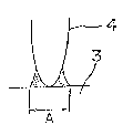
Brief description of the drawings
Fig. 1 is a side view showing the drawn-cup type evapora-
tor, Fig. 2 (A) and (B) indicate the parallel-flow type condens-
er, wherein (A) is a side view and (B) is a cross section at
AA' line, Fig. 3 is an oblique view showing a test piece of
inverted T joint, Fig. 4 is an oblique view showing one example
- 10 -
2(~C~66~
of serpentine type condenser belng a heat-exchanger for air
conditioner, and Fig. 5 is a side view magnified the fin portion
in Fig. 4. Best embodiment for putting the invention into
practice.
~Example 1 and Comparative example 1]
< Example 1 >
As shown in Fig. 4, a tube material (3) made of JIS A1050
(Al: over 99.5 %), which was molded into tube by hot extrusion
according to usual method, was bent in a serpentine shape,
corrugate fins (4) comprising a brazing sheet with a thickness oE
0.16 mm, the both sides of which were cladded with Al-10 % Si-
1 % Zn alloy skin material making Al-l % Mn-l % Zn alloy as a
core material, were inserted between these serpentine-shaped
tube materials (3), further connectors (5) comprising Al-4 % Zn-
1 % Mg alloy were attached and wire materials with a wire
diameter of 1.6 mm comprisng JIS A4047 (Al-ll to 13 ~ Si alloy)
were wound round these joined portions, thereby a condenser of
serpentine type was constructed.
After degreased with organic solvent, this assembly was
mounted on a stainless steel tray to be inserted into the
brazing furnace together with 346 g of KAlF4 per m3 of inner
volume of said brazing furnace. Then, this tray was inserted
into the electric furnace, which had been displaced by a nitrogen
gas atmosphere being at a dew point o~ -40C and containing
oxygen in a concentration of 100 ppm and retained at 610C, and
said assembly was heated for 5 minutes at 610C to perform the
- 11 -
, . ~,, .
06~iS~3
,
brazing.
At this time, KAlF4 melts and evaporates during the time
from having been inserted into the furnace to being raised to
the brazing temperature and covers the assembly as an atmosphere
at the time of brazing, thus it acts effectively as a flux.
Said condenser after the brazing was taken out from the
furnace, then external appearance of surface was observed and
situation of brazing was examined. These results are shown in
Table 1 as the inventive method No. 1. Thereafter, the chromate
treatment and the black painting were performed according to
usual methods and the adherence thereof is put down together in
Table 1 as a chromate processibility and a paintability,
respectively. Moreover, in order to evaluate the corrosion
resistance of this condenser after the painting, CASS test
based on JIS H8681 was carried out for 500 hours and the
existence of piercing pit corrosion was examined. These results
are also put down together in Table 1.
< Comparative example 1 >
~ Next, for comparison, said condenser assembly shown in
Fig. 4 was brazed by conventional method to investigate the
characteristics thereof.
Namely, after degreased with organic solvent, 10 % in
concentration of suspension of KAlF4 were coated onto the assemb-
ly shown in Fig. 4 ànd dried for 10 minutes at 200C. Thereafter,
this assembly was inserted into the electric furnace, which had
been displaced by a nitrogen gas atmosphere being at a dew point
of -40C and containing oxygen in a concentration of 100 ppm and
~retained at 610C, and heated for 5 minutes at 610C for brazing.
Subsequent processes were performed similarly to preceding
Example 1 and this brazed condenser was tested for evaluation
as above, the results of which are shown in Table 1 as the `:
comparative method No. 1.
~0~ 9
. ~ ~r ~
~ I, O ~0 0 bO O
," ~ ~ ~ , 4~
(a J- ~ n ~ 0-~1 tn
O tn a) o ~ o ~ c, o
~-rl O ~I-rl h ~1 C) ~ ~ h ~1
~ ~) aJ ~ ~1 ~ O ~J ~ ~ (I)
O ~ C O ~ 1 0 aJ-I~ O ~
h ~d ~ h ~ Q. ~J C~ ~ CJ E3
, ~ ~ I ~ .
rl ~ ~
,1 ~ P~ Ei
~ E~O
,1 O ~ 1-1 ~ ~ 4-
, tl) U~ ~d ~ O ~1 0 O ~1 _~
Ei ~ ~ C~ o o ~ u~
` O C~ ~ ~-~1 00~ ~S
0 ~1 ~ ~ C ~ ~ _~ t~
_ si h ~1~ __ æ--~ ~ ~
h .~
. ~ U~ ~,
~0 ~ ~ ~
b~ ~ O ~ O
~ ~ O ~ cq
.~1 ~ O O ~) rl U~
N h ' ~:L, E
O _ ~ .
0~ Oc~l 4
.,~ ~ ~ E~ u~ c~ 4 1
O ¢
,~: h a ~ ~ ~ a
~^ X o
~ .~ o ` o 4
E~ ~rl ~ ~ ~ O O r_
~ .~_, ~ ~ .n~ .
~-- ~: a _ ~ o
~ ~ ~ ~ ~ ~a
. o ~ ~l
4~ ~ ~ E~
~4 u~ ~ a) ~ ~3 ~ O E
e~ o 4~ c~ o a) ~I h
o ,
Cd 4~ a) ~ ~ _~
~ ~ ~ ~ rJ~'~
a) u~ .~ ~ ~ t
u) ~ ~ ~ ~ ~ O a) ,~
K c) P~ ~ J~ 4
P~i,~ u~ t~
æ _ h ~1
~ ~ 0
bO . ,l ~a ~ ~
~ '~7 ~ O ~ O ~ ~
N ~: ~ Ei J-) ~ cN
~ ~ ~ ~ O ~ ~ Q)
a~ ~ E c~ E o o
. .___ æ æ
- 14 -
.
~6~59
As evident from Table 1, the surface of the condenser a~ter
brazing according to the inventive method No. 1 was clean. As
for the situation of brazing, too, both the fin portions being ~-
joined portions of fin to tube material and the connector
portions being joined portions of connector-to tube material were
all e~cellent. Further, the chromate processibility and the
paintability were good and the corrosion resistance was also
good.
Whereas, with the condenser according to the comparative
method No. 1, the residue of flux adhered thickly and nonuniform-
ly over whole surfaces, which is not preferable from the external
appearance. Moreover, as for the situation of brazing, fin
portions were good, but connector portions were impossible to
braze. Further, the chromate treatment and the paintability
after the brazing were nonuniform and, as for the corrosion
resistance, the piercing pit corrosion generated particularly
at the curved portions (6) of tube material (3) shown in Fig. 40
[Example 2 and comparative examples 2 and 3]
< Example 2 >
A parallel-flow type condenser as shown in Fig. 2 (A) and
(B) was constructed using following components and brazed for
joining bg the inventive method. Namely, the parallel-flow
type condenser was constructed in such a way that, into a seam-
welded pipe (7), which was produced in a Elat shape by molding
a rolled plate with a thickness of 0.4 mm comprising a brazing
sheet according to JIS BAllPC cladded one side with aluminum
.. ,.; ,.
, : ; ;
_ ~ ~ 0 ~ 6 ~ ~
alloy brazing material containing 6.~ to ~.2 ~ oE Si making JIS
A3003 (Al-0.05 to 0.20 % Cu-l.0 to 1.5 % Mn) aluminum alloy as
a core material after degreased beforehand with organic solvent
and the outside of which is cladded with brazing material, an
inner fin (8) with a thickness of 0.16 mm comprising a brazing
sheet according to JIS BA12PC cladded both sides with aluminum
alloy brazing material containing 6.8 to 8.2 % Si making JIS
A3003 aluminum alloy, onto which 10 % in concentration of
suspensior. of KAlF4 are coated and dried, as a core mateirial was
inserted, further, a plurality of such seam-welded pipes (7)
and a plurality of outer fins (9) comprising Al-0.15 % Cu-1.2 %
Mn-l % Zn alloy and being processed in a corrugate shape were
superposed alternately, side plates (10) with a thickness of 1.2
mm comprising JIS BAllPC were disposed to the ou~side of outer-
most outer fins (9), pipes (11) with a thickness of 1.2 mm and
an outer diameter of 16 mm comprising JIS BAllPC cladded outside
with brazing material were connected to both sides of seam-
welded pipes (7), respectively, and connectors (5) comprising
Al-5.7 % Zn-l % Mg alloy were attached to each end of said pipes
~11) .
This assembly was mounted on a stainless steel, on which
500 g of KAlF4 per m of inner volume of brazing furnace were
placed. And, this tray was inserted into the electric furnace 9
which had been displaced by a nitrogen gas atmosphere being at
a dew point of -40C and containing oxygen in a concentration
of 100 ppm and retained at 610C, and said assembly was heated
- 16 -
~' ''' ~` ' ~
0 6 ~ ~ ~
for 5 minutes at 610C to perform the brazing. At this time,
KAlF4 melts and evaporates during the time from havlng been
inserted into the furnace to being raised to the brazlng tempera-
ture and covers the assembly as an atmosphere at the time of
brazing, thus it acts effectively as a flux.-
Said condenser after the brazing was taken out from thefurnace then, external appearance of surEace was obserbed and
situation of brazing was examined. These results are shown in
Table 2 as the inventive method No. 2. Thereafter, the chromate
treatment and the black painting were performed according to
usual methods and the adherence thereof is put down together in
Table 2 as a chromate processibility and a paintability,
respectively. Moreover, in order to evalua-te the corrosion
resistance of this condenser after the painting, CASS test based
on JIS H8681 was carried out for 500 hours and the existence of
piercing pi-t corrosion was examined. These results are also
put down together in Table 2.
< Comparative examples 2 and 3 >
Next, for comparison, using same components as above, a
parallel-flow type condenser constructed by inserting an inner
fin (8) without KAlF4 coated into a seam-welded pipe (7) was~
brazed under same conditions as those in preceding Example 2 and
the observation of external appearance etc. were made. The
results are put down together in Table 2 as the comparative
method No. 2.
Further, for comparison, said assembly of condenser shown
0~6~ 3
in Fig. 2 (A) and ~B) was brazed by conventional method and
the characteristics thereof were investigated. Namely, after
degreased with organic solvent, this assembly was coated with
10 % m concentration of suspension of KAlF4 and drying was
made for 10 minutes at 200C. This coating and drying processes
with KAlF4 suspension are necessary to be made twice on both
inside and outside.
Thereafter, this assembly was inserted into the electric
furnace, which had been displaced by a nitrogen gas atmosphere
being at a dew point of -40C and containing oxygen in a
concentration of lO0 ppm and retained at 610C, and heated for
5 minutes at 610C to perform the brazing. Of this brazed
parallel-flow type condenser, similar eveluation tests as above
were carried out, the results of which are put down together in
Table 2 as the comparative method No. 3.
,
2~j6~3
~ ~ ~ ~ ~l ~ -
o c~ l o ~o o l o ~o o ~o o
.~ ~: ~ ~ ~ a) ~: ~ , ~ ~
U~: ~ ~ ~ ~ O~rl tn
o ~ a) o c~ o ~ o c) o ~ c, o
u~ ~)~ br~ I h O ~ ) I h
~ ~1 ~ O ~ 5~ ~ a) ~ ~1 ~ o aJ
O U~ O ~ 1 0 O t~ l O 0~0
~ æ ~ ~ Q. c~ æ ~ ~ ~
., ' ':. ~
. :
s~ : . .
?~ ~ O
J-
~ .~ . o,-
a~ ~ ~ ~o ~ ~o)~_~ o~
~ O aJ O a~ P~~
C~ ~ C~ ~ ~ ~ O
~ a) w ~ o ~ 4
o ~ ~^ ~ ~ æ~
O ~ ~ ?~ a o
¢~ ¢~
C~ :4 ~ _, _, _,
~ . a)
O .n
~: ~ rl
C) o ~ ~ ~ U)
~1 O O .~ ~
J-) O O ~ O
~ ~1 C~) t~ ~ Q,
O O o orl E~
~1
't'nl ~_
~ J_) a
.,1 ~ P~
N O ~r~ O
0 P~ r~ ~:1 ~ ~
h I ~) O O O
~:: S~ O O O
~ '~ ~ CO C~ C~
C~l O
O _ ~_ _ _
~1 ' ~ 1~; ~r~ ~1
,n ~ a) .
0 ~ 4~ '
E~ :~ .,1 'O ~ ~ ~,q ~
c~ S~,l O .,~ cq O
~,1 ~ ~ ~ O S O O
Ct~ H S~ O ~ . ~. C~)
~ ~ 1
I
.
~J
~ 0~a ~ a
h ~ C~ ~ ~ ~r~
0 x t~ x ~a x ~ u~
a
a~ ~ ~ a) ~ ~ :~
4~ 4~ 4~ 1
a~ ~n u~ ra
c~ ~ cq ~ ~n 4~ ~ O
~1 0 O a)~l o ~ o 0 ~
t~ ~1 ~ ~ ~1
s ~ ~ a
:~ c
~n ~ ~1 ~d ~ ~ ~ ~ a) ~ o
~r~ ~S ~ ~rl ~S ~ .~ tl7 a.
X 4~ u~ S~ S~ ~n S~ ~ tn ~ ,~
~1 0 O ~d ~ a) 0 ~ a) a
~,C U~ ~,~ ~:;,9 0 ~ a
æ c~ c~
. .
. ~
a) .,,
~ ~ .,~
~1 o ~ ra ~ ~
N ~ S:: O ~ O
0 ~1 (1)
J-
~:1 Ei ~ O O O
H Ei ~ Ei
19 -
~ ~ ~ 6 6~3
., .
As evident from Table 2, the surface of the condenser after
the brazing according to the inventive method No. 2 was clean. ~
As for the situation of brazing, too, all of the joined portions, - ;
that is, joined portions of outer fin to seam-welded pipe, joined
portions of inner fin to seam-welded pipe, joined portions of
seam-welded pipe to pipe, joined portions of Mg-containing
connector to pipe, etc. were excellent in the brazability.
Further, the chromate processibility and the paintability were
also good and the corrosion resistance was also excellent.
Whereas, with the condenser according to the comparative
method No. 2 inserted the inner fin without KAlF4 coated into the
seam-welded pipe, though the situation of brazing at the outslde
joined portions was good, the inside joining portions of inner
fin could not be brazed.
Moreoverj with the condenser according to the comparative
method No. 3, the residue of flux~adhered thickly and non~
uniformly over whole surface, which is not preferable from the
external appearance. As for the situation of brazing, almost
all joined portions were good, but the joining portions of Mg-
containing connector to pipe could not be brazed. Moreover,
the chromate treatment and the painting after the bra~ing were
nonuniform. As for the corrosion resistance, the piercing pit
corrosion generated at the portions of pipe (11) shown in Fig. 2.
[Examples 3 through `6 and Comparative examples 4 and 5]
< Examples 3 through 6 >
Test pieces of inverted T joint as shown in Fig. 3 were
- ~0 -
6 ~ ~
constructed, wherein one edge of rolled plate (1) with a thick-
ness of 1 mm comprising a brazing sheet according to JIS BA12PC
cladded one side of core material according to JIS A3003 Al
alloy with JIS A4343 Al alloy brazing material containing 6.8
to 8.2 % of Si was contacted with the face of respective Al
alloy plates (2) with a thickness of 1 mm, which are shown in
Table 3, so that both plate materials (1) and (2) became to be
perpendicular each other, and the brazing was carried out under
following conditions to investigate the situation of brazing.
Namely, the test piece of inverted T joint in Fig. 3 was
degreased with organic solvent and, after mixed a mixture of
32 % I~F-68 % ZrF4 with Al powder with an average particle size
of 70 ~m in equal amount, 500 g of said final mixture per m3 of
inner volume of brazing furnace were placed in this brazing
furance. And, the inside of this furnace was displaced by a
nitrogen gas atmosphere being at a dew point of -40C and
containing oxygen in a concentration of 100 ppm and further
retained at 610C. The assembly in Fig. 3 was then inserted
into the furnace and heated for 5 minutes at 610C to perform
the brazing.
Thereafter, said joined product of inverted T joint after
the brazing was taken out from the furnace and the situation of
brazing was examined. The results are put down together in
Table 3 as the inventive methods No. 3 through No. 6. Besides,
in the table, mark O indicates a good situation of brazing and
mark X indicates a poor situation of brazing.
, ~ :
,., :
:~0~.6~;~
< Comparative examples 4 and 5 ~
- Also, as the comparative examples, said rolled p~ate (1)
and Al alloy plates (2) shown by the comparative methods No. 4
and No. 5 in Table 3 were constructed to the test pieces of
inverted T joint as shown in Fig. 3 according to the conventional
method and degreased. Then, this assembly was coated with 10 %
in concentration of KAlF4 and dried. Thereafter, similarly to
the preceding examples, this assembly was inserted into the
electric furnace, which had been displaced by a nitrogen gas
atmosphere being at a dew point of -40C and containing oxygen
in a concentration of 100 ppm and retained at 610C, and heated
for 5 minutes at 610C to perform the brazing. The situation
of brazing was investigated similarly and the results were put
down together in Table 3.
Table 3
. _.
Brazing method No. Al alloy plate Brazability
Inventive method 3 JIS A1050 O
- 4 JIS A3003 O
.. 5 Al -0.7 % Mg O
_
6 Al - 1.0 % Mg O .
Comparative method 4 JIS A1050
. .. 5 Al - 1.0 % Mg
As can be seen from Table 3, in the cases of the inventive
methods No. 3 through No. 6, the brazability was good in all
cases and, in particular, good brazing was possible even with
- 22 -
;
2~
the Mg-containing materlals. Whereas, with Al-l.0 % Mg material
of the comparative method No. 5, the brazing was impossible.
[~xample 7 and Comparative example 6]
< Example 7 >
As shown in Fig. 4, a tube material (3) made of JIS A1050,
which was molded into tube by hot extrusion according to usual
method, was bent in a serpentine shape, corrugate fins (4) com-
prising a brazing sheet with a thickness of 0.16 mm, the both sides
of which were cladded with Al-10 % Si-l % Zn alloy skin material
making Al-l % Mn-l % Zn alloy as a core material,were inserted
between these serpentin-shaped tube materials(3), and further
connectors (5) comprising Al-4.3 % Zn-1.3 % Mg alloy were at-
tached, thereby a condenser of serpentine type was constructed.
Besides, these joining portions of currugate fin (4) to connectors
(5) had been joined beforehand by TIG welding using a welding rod
according to JIS A1070 (Al: over 99.70 %).
Next, after degreased this assembly with organic solvent9
500 g in total of equal mols of KF and AlF3 per m3 of inner
volume of brazing furnace were placed in the electric furnace
for brazlng. Said assembly was inserted into this electric
furnace, which had been displaced by nitrogen gas being at a
dew point of -40C and containing oxygen in a concentration of
100 ppm and retained at 610C, and heated for 5 minutes at 610C
to perform the brazing.
Said condenser after the brazing was taken out, then,
external appearance of surface was observed and situation of
~ jfi,t7~
brazing was examined. These results are shown in Table 4.
Thereafter, the chromate treatment and the black painting were
performed according to usual methods and thé adherence of these
films is put down together in Table 4 as a chromate processibility
and a paintability, respectively. Moreover, in order to evaluate
the corrosion resistance of this condenser after the painting,
CASS test based on JIS H8681 was carried out for 500 hours and
-the existence of piercing pit corrosion was examined. These
results are also put down together in Table 4 as the inventive
method No. 7.
< Comparative example 6 >
Further, for comparison, said assembly of serpentine type
condenser shown in Fig. 4 was brazed by conventional method
shown in Comparative example 1. Of this, similar evaluation
tests as above were carried out and the results are shown in
Table 4 as the comparative method No. 6.
- 24 ~
fi~ ~
~ ~ ' ..
~ U ~ ~ o~ .
O ~: h bO 0 ~ O ~1
J~ 1 v ~ ~,~ ~
u~ V ~: 0~ t~ O cq v
O cn al O O h~l O O
h ~1 t~O ~ h h O ~ h E~
. h u~ O ~J v ~ ~:; ~ h
o a~o~,J ri rl Oa) L~l rl O
C~ h æ ~ , ~ o ~ c
_
:~ ~ ~
E
~rl rl ~ h .~
,n ~( ~) ~1 ~ O o
O ~ O ~ E O ~ ~H .r~ :'
.LI C~ ~ O a~ h O a)-~l
~ u~ td C~) ~1 0 b~
E O v ~ ~1 aJ :~)
O C~ ~ .~ ~ O ~ ~ ~
h o ra ~1 ~ Z ~ O O
,S ~ ¢ ~ ¢ ~:
~ ~ _ _, h
_ I ,n
~ .
~ ~0
bO 4~ ~ æ .,
~ o c~ u~ ~n
N ~: v ~~'7 ~1 rl O ~:
. . 4~ o rl
h ~t)~( E~ ~1 ~1
~ g ~ ~ _ ~0 ~ ¢
4~ ~1 ~1 4
O V U~ ~ ,D
oh - --
G) O ~ ~ 4
.~ bO^ ~
. 4~ 0
~ ~ .,~ ~ O o ~ O ~
E~ ~ 4~ ~ a) ~ o o o CR
~ rl V ~ ~ ~ U~
rl ~ O ~a h ~ ,C
U~ 0 '~ h
I ~ ~U
_
O
~~ ra ~ ~ ~ ~ ~0
5-1~) ~ . ~ 1 h 0
0 ~ o v a
X0 ~ . 0 ~ ,~
~ :~ ~ O~ 1 ~ E-( E
P~ ~1 aJ ~1~ ~ ~:: ~ _
0 a) 4~ )4~ ~:) h ~ ~ ~3
C~ C~~ ~;-,1
0 ~ U~4~ ~ O ~ 11 _~
0 4~ O aJ-,~O ~ ~
~ h ~ u~ ~ v
h ~J a) a)aJ ~ S 1
a) ~n ~1 ~ C.l~
J_\ ~ rc ) a) S~l J--) ~1
x ~, .,., ~ ~, .,, tl~ aJ a) ~rl
O u~ h h `0 ~ .~ ~ 4-
a
P~ ~ ,D ~ ~ h 4~
_ ~ O
O
æ r~ ~O
~o
. ~ - .~,
~ o
Q) .,
b~
~ ~ .,~
~, O
N ~C ~ O t~ O ~I C~l
~a v a~ ~ P~ ~
h a) ~ ~ e~ 1~ ~ ~
~q ~ ~ ~ o a) ~ v
H E C~ æ æ
- 25 -
'~ O ~ 5 ~
As evident from Table 4, the surface of the condenser after
the brazing according to the inventive method No. 7 was clean and ~ '
the situation of brazing was also good. Further,'the chromate' `~
processibility and the paintability were also good and the
corrosion res]stance was also good. --
~
Whereas, with the condenser according to the comparativemethod No. 6, the residue of flux adhered thickly and nonuniform-
ly over whole surface, which is not preferable from the external
appearance. Moreover, though the situation of brazing was good,
the chromate treatment and the painting after the brazing were
nonuniform. As for the corrosion resistance, the piercing pit
corrosion generated at the curved portions (6) of tube material
(3) shown in Fig. ~.
[Examples 8 through 11 and Comparative examples 7 and 8]
< Examples 8 through 11 >
As shown in Flg. 3, test pieces of inverted T joint were
constructed, wherein one edge of rolled plate (1) with a thick-
ness of 1 mm comprising a brazing sheet according to preceding
JIS BA12PC was contacted with'the face of respective rolled
plates (2) with a thickness of 1 mm, which are shown in Table 5,
so that both plate materials (1) and (2) became to be perpendicular
each other, and the brazing was carried out under following
conditions to investigate the situation of brazing.
Namely, after the test piece of inverted T joint shown in
Fig. 3 was degreased with organîc solvent and a mixture of 250 g
of KBF4 with same 250 G Al powder with an average particle size
- 26 -
~, :
, ~ :
,,,. . - , , ,:
~ ~ ~ 6 ~
.
of 70 ~m per m3 of inner volume of brazing furnace was placed
in this electric furnace for brazing, the inside of this
.
furnace was displaced by a nitrogen gas atmosphere being at a
dew point of -40C and containing oxygen in a concentration of
100 ppm and further retained at 610C. Into this furnace, said
assembly shown in Fig. 3 was inserted and heated for 5 minutes
at 610C to perform the brazing.
Thereafter, said joined product of inverted T joint after
the brazing was taken out from the furnace and the situation of
brazing was examined. The results are put down together in
Table 5 as the inventive methods No. 8 through No. 11. Besides,
in the table, mark O indicates a good situa~ion of brazing and
mark X indicates a poor situation of brazing.
< Comparative examples 7 and 8 >
Also, as the comparative examples, said rolled plate (1)
and Al alloy plates (2) shown by the comparative methods No. 7
and No. 8 in Table 5 were constructed to the test pieces of
inverted T joint as shown in Fig. 3. Then, the brazing wa.s
carried out by the similar method to comparative examples 4 and
5 and the situation of brazing was investigated similarly to
preceding examples, the results of which are put down together
in Table 5.
- 27 -
~0C~6fi~
Table 5
Brazing method No. ¦ Al alloy Brazability
Inventive method 8 l JIS A1050 _
¦ 9 JIS A3003
¦ 10 Al- 0.7~%:Mgz
" ¦ ll Al- 1.0 % Mg O
I
Comparative method¦ 7 JIS A1050
¦ 8 Al- l 0 % Mg ~ X
As can be seen from Table 5, in the cases of the inventive
methods No. 8 through No. 11, the brazability was good in all
cases and, in particular, good brazing was possible even with the
Mg-containing materials. Whereas, with Al-1.0% Mg material of
the comparative method No. 8, the brazing was impossible.
[Example 12 and Comparative example 9]
< Example 12 >
Similarly to Example 7, a condenser of serpentine type as
shown in Fig. 4 was constructed. Besides, the joining portions
of corrugate fin (~) to connector (5) had been joined beforehand,
similarly to Example 7, by TIG welding using a welding rod
according to JIS A1070.
Next, after degreased this assembly with organic solvent, a
mixture of 250 g of KZnF3 with same 250 g of Al powder with an
average particle diameter of 70 ~m per m3 of inner volume of
brazing furnace was placed in the electric furnace for brazing.
Said assembly, was inserted into the electric furnace 9 which had
been displaced by a nitrogen gas atmosphere being at a dew point
- 28 -
-,. . ...
. . .
6~i~J~
of -40C and containing oxygen in a concentration of 100 ppm
and retained at 610C, and heated for 5 minutes at 610C to -; ;
perform the brazing.
Said condenser after the brazing was taken out from the
furnace, then, external appearance of surface was observed and
situation of brazing was examined. These results are shown in
Table 6 as the inventive method No. ]2. Thereafter, the chromate
treatment and the black painting were performed according to
usual methods and the adherence of these films is shown in
Table 6 as a chromate processibility and a paintability,
respectively. Moreover, in order to evaluate the corrosion
resistance of this condenser after the painting, CASS test based
on JIS H8681 was carried out for 500 hours and the existence of
piercing pit corrosion was examined. These results are also
put down together in Table 6.
< Comparative example 9 >
Further, for comparison, said assembly of serpentine type
condenser shown in Fig. 4 was brazed by conventional method shown
in Comparative example 1. Of this, similar evaluation tests as
above were carried out and the results are shown in Table 6 as
the comparative method No. 9.
- 29 -
__ . ~ G I
t~ c) ~ o Q-~l O
O S ~ bS~ ~1 .,~ c~ h
.,~ t~ a) ~1 ~; ~l ~ ~ 1 . .
U~ ~ ~ O-~ O ~ aJ O
O ~q ~ C~ U ~1 0
,1 ~0 G ~ ~:: O ~ ~:: t~
~1 Ul O ~J J ) O ~: ~ O
o a~ o ~ ~ a~ o
c, s~ æ ~ ~ ~ c~ ~ o ~ u~ E~ .:
I I ~
~ ~_ ~ ' .
.~ P~
,l ~ E
~r~ ~ O a
oq ~ ~3 ~H ~
U~ ~ ~ .,1 ..,~ .
a) ~1 O ~ O
C) ~ ~ ~ ~ ~
O ~,1 0~,1 O ~:: G
1~ ~ O G O O
~a ~) ~ br~ G 4~
o a o
æ
~1
~ ~ a
o ~ ~ P
ra ~ ~ E
¢ d ~ .
c~ ~ ~, ~, æ ~o
_ I G ~:4
b~O ~r~ O
~:: ~ ,_ ~ o G
.~ O C~l ~ ~r~
N _~ i~ oo 4-1
5~ ~ ~ o X 'C
~ v a~ E . .
P G ~0~--~ ~ ~ u~
O ~ ~ ~:
~rl a~1
o v ~ ~ a) 4~ ~:
h ~ ~ 3
G O l 4~ 0
O ~ ~o,_ ~ O
~1 ~ ~ O u~
o o ~q
';:; ~ ~ O O h ~ ,5
,~ ~ ~1 a) ~ ~
I ~ . ~ a~ ~o
r~ V ~ h ~ P~ G
u~ ~ ~ aJ
I ~ 40
a)
G ~ u
~d ~ ~ ~ c~
h X c~ x~a O ~~r~
:~ G u~ E~ ~i
~ ~ ~ ~ ~ ~ ~ _ ~
Q. (~ p h ~ h ~ ~ G Ei
G a) ~ ~ ~3
~d a) 4~ P~ u) 4
CJ O ~1 . O O ~ h ~)
G u~ ~ o h
~J h ~ td O ~,1 1~ a)
G h ~ ~ ~ ~ ~ a) L) .,1~ ) ~_
h ~ ~ ~1 'C) ~ ~ ~1
a) u~ ~ G c) .,~ ~ ~n a) ~,1
~ ~n ~ a) v~ G ~ G :~J~ 4
x ~ ~ al ~ QJ O
O Pi ~ rl P~
~0
. c~l ~ .~ ~
O ~ G G
. u~ o
G ra ~ ~ ta ~ ~
~,1 0 ~:; O h O ~ CN
a~ ~ ~ ~
~ ~ ~ ~ ~ ~ ~ (U
h a~ ~ U~ . ~3 a) ~) ~
~:4 E ~ E ~ . æ Z
~ 30 -
' . ': : .
.~
As evident from Table 6, the surface of the condenser after
the brazing according to the inventive method No. 12 was clean
and the situation of brazing was also good. Further, the
chromate processibility and the paintability were also good
and the corrosion resistance was also good.
Whereas, with the condenser according to the comparative
method No. 9, the residue of flux adhered thickly and non-
uniformly over whole surface, which is not preferable from the
external appearance. Moreover, though the situation of brazing
was good, the chromate treatment and the painting after the
brazing were nonuniform. As for the corrosion resistance, the
piercing pit corrosion generated at the curved portions (6) of
tube material (3) shown in Fig. 4.
[Examples 13 through 16 and Comparative examples 11 and 12]
< Examples 13 through 16 >
As shown in Fig. 3, test pieces of inverted T joint were
constructed, wherein one edge of rolled plate (l) with a
thickness of l mm comprising a brazing sheet according to
preceding JIS ~A12PC was contacted with the face of respective
rolled plates (2) with a thickness of 1 mm, which are shown in
Table 7, so that both plate materials (1) and (2) became to be
perpendicular each other, and the brazing was carried out under
following conditions to investigate the situation of brazing.
Namely, after the test piece of inverted T joint shown in
Fig. 3 was degreased with organic solvent and 500 g of equal
mols oE KF and AlF3 per m3 of inner volume of brazing furnace
.. . .
were placed in this electric furnace for brazing, the inside o~
this furnace was displaced by a nitrogen gas atmosphere belng
at a dew point of -40C and containing oxygen in a concentration -
~of 100 ppm and further retained at 610~C. Into this furnace,
the assembly in Fig. 3 was inserted and he~ated for 5 ~inutes
at 610C to perform the brazing.
Thereafter, said joined product of inverted T joint after
the brazing was taken out from the furnace and the situation of
brazing was examined. The results are put down together in
Table 7 as the inventive methods No. 13 through No. 16. Besides,
in the table, mark O indicates a good situation of brazing and
mark X indicates a poor situation of brazing.
< Comparative examples 11 and 12 >
Also, as the comparative examples, said rolled plate (1)
and Al alloy plates (2) shown by the comparative methods No. 11
and No. 12 in Table 7 were constructed to the test pieces of
inverted T joint as shown in Fig. 3. Then, the brazing was
carried out by the similar method to comparative examples ~ and
5 and the situation of brazing was investigated similarly to
preceding examples, the results of which are put down together
in Table 7.
- 32 -
,,
.
, -::::
.. . .
Table 7
Brazing methodNo. ¦ Al alloy Brazability
, __ , ~ ~,
Inventive method 13 ¦ JIS A1050
,.14 ¦ JIS A3003 O
j Al - 0.7% Mg O
.
"¦ 16 ¦ Al - 1.0% Mg O
_ ~
Comparative method 11 ¦ JIS A1050 O
. I
.. 12 ¦ Al - 1.0% Mg
As can be seen from Table 7, in the cases of the inventive
methods No. 13 through No. 16, the brazability was good in all
cases and, in particular, good brazing was possible even with
the Mg-containing materials. Whereas, with Al-l.0 ~ Mg material
of the comparative method No. 12, the braæing was impossible.
[Example 17 and Comparative example 13]
< Example 17 >
Similarly to Example 7, a condenser of serpentine type as
shown in Fig. 4 was constructed. Besides, the joining portions
of corrugate fin (4) to connector t5) had been joined beforehand 9
similarly to Example 7, by TIG welding using a welding rod
according to JIS A1070.
Next, after degreased this assembly with organic solvent,
500 g of equalmols of KF and AlF3 per m3 of inner volume of
brazing furnace were~placed in the electric furnace for brazing.
Said assembly was inser~ed into the electric furnace, which had
been displaced by a nitrogen gas atmosphere being at a dew point
of -40C and containing oxygen in a concentration of 100 ppm and
- 33 -
~. ,
~ OG6S~
retained at 610C, and heated for 5 minutes at 610C to~perform
the brazing. -
Said condenser after the brazing was taken`out from thefurnace, then, external appearance of surface was observed and
situation of brazing was examined.~ These results are shown in~
Table 8 as the inventive method No. 17. Thereafter, the
chromate treatment and the black painting were performed
according to usual methods and the adherence of these films is
put down together in Table 8 as a chromate processibility and a
paintability, respectively. Moreover, in order to evaluate the
corrosion resistance of this condenser after the painting,
CASS test based on JIS H8681 was carried out for 500 hours and
the existence of piercing pit corrosion was examined. These
results are also put down together in Table 8.
< Comparative example 13 >
Further, for comparison, said assembly of serpentine type
condenser shown in Fig. 4 was bra~ed by conventional method
shown in Comparative example 1. Of this, similar evaluation
tests as above were carried out and the results are shown in
Table 8 as the comparative method No. 13.
. .
~ ~, , , o ~ o ,,
O ~ ~I bl) h ~ 1 t~
.~ t~JO ~ ~ ~ L) C) ~ ' J-l
U~ ~)1::; 0~1 0 t~ ~1 0 O
o u~ a) u o ~ J
~ ~ a) P~
~ ~ O ~ ~ O ~ ~ O
O O O ~ 1 0 4-1 rl ~1 , ,!~
~1Z ~ ,~ Q, U~J ~) 0 ~
~-~1 ~a
~ l l ~
~ ~1 ~::; !::
~P ~ O^ .,~
~ :~ ~ ~ O
a)~ ~ ~ a ~ ~a~e
O ~ ,_ O ~ ~
o s~ ~ o ~ o
6 0 ~ ~ 0 ~1 b~
o ~. ~ e .~-,, O
~ o~ ~ ~ o ~a ~
o æ G ~ S~
~, ~_ ,n u~
~ 4~,_ ~
rl O C~ ~ O
N ,~ J-) Lr~ CN ~1 0
h ~1 ~1 ~ ~ t~) ~1 r l
~ o ~ e~ ~ ~o x ¢
oO ~,1
o
a~ ~ o ' . ,~ ~ ~
o ~ ~ o o~ O ~U 3
U~ t~l ~ ~h ~ O
_ e
~ ~ O
~ ~3 ~ ~
Xu ~ 1~
o ,9 .
,9 h 4~ ~ ~ ~
~d ~~?~tn ~ e ~ ~ ~ e
C)O ~1 .O ~) ~ h ~ ~:
C~ U~ tll O h
çd 4-1 G) h ~ 0 4-l-rl
h~ ~ ~,
U~ ~ C) ~ ~_
a) u~
x 4~ ~ ~ a) tna) ~ ~ o
W O ~ n,1 ~ c~ 4
_ _ h ~1
. ~ ~
æ l- ~ ~ ~
o
~ l ~
b~ ~
.~ O ~ O h
N ,C a) ~ ~::4
~d ~ ~ ~e ~ ~ ~ a)
h CU ~: O0-~ 0 Ll ~
e H eC~ ~ e æ
æ
- 35 -
As evident from Table 8, the surface oE the condenser
after the brazing according to the inventive method No. 17`was
clean and the situation of brazing was also good. Further, the
chromate processibility and the paintability were also good and
. . .
the corrosion resistance was also good.
Whereas, with the condenser according to the comparative
method No. 13, the residue of flux adhered thickly and nonuniformly
over whole surface; which is not preferable from the external
appearance. Moreover, though the sicuation of brazing was
good, the chromate treatment and the painting after the brazing
were nonuniform. As for the corrosion resistance, the piercing
pit corrosion generated at the curved portion (6) of tube material
(3) shown in Fig. 4.
Utilizability in the industry
As described above, in accordance with the invention, the
production cost of, for example, heat-exchanger for cars etc.
becomes more inexpensive over the conventional brazing method
because of shortening of production process, the surface processi-
bility in the post-treatments such as chromate treatment etc. is
good because of clean surface of components after the brazing,
the qualities such as being excellent in the corrosion resistance
etc. are enhanced, and further the brazing of alloys containing
much Mg is also possible. For these reasons and others, the
invention exerts conspicuous effects industrially.
- 36 -