Note: Descriptions are shown in the official language in which they were submitted.
~006~
, ~
INTRAOCULAR LENS_W TH EXPANDABLE HAPTIC
Speci ication
This application is a continuation in part of U. S.
Patent Application Serial No. 07/337,260, filed April 13,
1989.
Backqround of the Inve~tion
Field of the_Invention
The invention relates to an intraocular lens for the
human eye.
. "
Descriptio~ of the Prior Art
It has been a continuing goal in ophthalmology to
develop an intraocular lens which can be placed through the
smallest incision possible. There have been four basic
approaches to intraocular lens design to accomplish this
task:
1. The development of intraocular lens implants made of
flexible materials which are foldable and can be
implanted through a small incision in their smaller,
folded state, to then have the implant unfold to its
full size within the eye. Examples of such foldable
designs are seen in the patent of Mazocco 4,573,998.
2. The development of intraocular lens implants made of
expandable materials which combine witll water and which
are implanted into the eye in their smalle~, dehydrated
state and then expand their volume once they are placed `"
into the liquid-containing interior of t~le eye. ;
Examples of this type of design are seen in patents `~
4,556,998 and 4,734,095 by Siepser, and 4,710,194 by `
Kelman, and 4,449,257 by Koeniger.
3. The development of intraocular lens implants containing
two or more separate or moveable pieces which required
~ .,
;,'
..
, ~ .
2006~2
construction once placed within the eye. In some
designs, the pieces are connected together but require
repositioning (such as sliding) within the eye after
implantation. Examples of this type of design are seen
in patent 4,056,855 by Kelman, 4,636,210 by Hoffer, and
4,6~,716 by Mackool.
4. ~ntraocular lens implants constructed to have an
inflatable optic c~amber or compartment which is
expandable within the eye by means of in~ection of a
suitable fluid-like material into the initially
deflated chamber which then expands to produce the
optic when completely inflated. This type of design is
seen in patents 4,585,457 by Kalb, 4,693,717 by
Michelson, and 4,373,218 by Schachar.
Presently, with currently available technology and
materials, it appears that the inflatable type of
intraocular len~, which can be implanted in its uninflated,
rolled up or compressed condition and then re-expanded in
the eye with injection o~ the proper fluid-like material,
stands the best chance of bein~ the implant design
implantable through the smallest incision. IIowever, all of
the existing inflatable designs proposed to date involve
inf~ating the optic and that is a very unacceptable design
feature because, by involving the optic in the inflation
process, the optical quality of the implant is necessarily
affected by and dependent on the inflation prdcess. More
specifically, the optical quality and function will depend
on the exact volume and quality o~ fluid-like material
injected during the inflation process, and the skill of the
surgeon performing the inflation. Also, the possibility of
leaks from the inflated optic cavity might result in a
change in the optic shape (and therefore its optical power)
and forever threatens the fu~ure optical quality of the
implant. This dependency of the optical quality (and
'''' ;`' S ~ ' ' , o ' :.. , .,".,.~ . ","" ~
;20067~
therefore the i~plant's ability to restore good vision to
the patient) on the inflation o~ tpe optic is a sexious and
permanent design flaw for any infl~table design involving
the optic. This possible optical variability is also a
potential problem in those designs in which the optic
dimensions will change with the combination of the optic
material with fluid, such as the designs of Siepser. To a
lesser extent, the optical quality of foldable materials is
a potential problem which has been largely overcome through
materials development. Potentially, the problems of the
inflatable optic designs can likewise be overcome, however,
there does not appear to be a practical and usable solution `
available in the near future. ~;
Therefore, it would be desirable to develop an implant
design which incorporates the advanta~eous features of
inflation or expansion for volume reduction/enlargement to
allow implantation throuyh the smallest incision possible,
and yet has an optic o~ established and constant optical
quality which is independent of the inflation or expansion
mechanism. ;
Summary of_the I~ve~tio~
It is an object of the invention to provide an
intraocular implant comprising a non-expandable optic which
comprises a haptic means which is expandable by fluid. In
this way, the optic qualities are completely independent,
stable and unchanging regardless of
the success and quality of the expansion process.
Difficulties with the expansion of the haptic, should they
occur, would affect only optic centration and not optic
quality.
It is a further object of the invention to provide an
intraocular implant for use as an artificial lens implant in
a human eye and which comprises a, non-expandable, solid
optic member having a central axis and
.. .... ....
200~7~
an outer periphery and an expandable haptic means coupled to
the outer ~eriphery of the optic member. The haptic
means is expandable after insertion into the eye, in a first
embodiment, py externally injected fluid, and in a second
embodiment by moisture in the eye.
In the first embodiment, the in~latable haptic means
comprises a flexible wall structure coupled to the outer
periphery of the optic member defining at least one enclosed
chamber for receiving a fluid for inflating the haptic
means.
In the second embodiment, the haptic means is formed of
a material capable of combining with or taking up liquid
from the aqueous of the eye resulting in expansion of the
haptic means.
Brief Description of the Drawinqs
Fig. l is a plan view of the intraocular implant of a
first embodim0nt of the invention with the haptic
uninflated.
Fig. 2 is an enlarged cross-section of Fig. 1 taXen
along lines 2-2 thereof.
Fig. 3 is an enlarged cross-section of the intraocular
implant of Fig. 1 with the uninflated haptic in a folded
position.
Fig. 4 is an enlarged cross-section of the intraocular
implant of Fig. l with the haptic inflated.
Fig. 5 illustrates the intraocular implant, in
cross-section, with the haptic inflated and positioned
within the capsular bag o~ a human eye.
Fig. 6 is a cross-sectional view of the intraocular
implant illustrating one-way valves for use for inflating
the chamber of the haptic.
Fig. 7 is a plan view of a modification of the
embodiment of Fig. 1-6 with the haptic members uninflated.
~ ;z ::
~
Fig. 8 is an enlarged cross-saction of Fig. 7 taken
along lines 8-8 thereof.
Fig. 9 is an enlarged cross section of ~he intraocular
implant of Fig. 7 with the uninflated haptic members in
folded positions.
Fig. 10 is an enlarged cross-section of the intraocular
implant of Fig. 7 with the haptic members inflated.
Fig. 11 is a plan view o~ a second embodiment of the
invention with the haptic unexpanded.
Fig. 12 is an enlarged cross-section of Fig. 11 taken
along lines 12-12 thereof.
Fig. 13 is an enlarged cross-section of the intraocular
implant of Fig. 11 with the haptic expanded.
Fig.14 is a plan view of a modification of the
embodiment of Figs. 11-13 with the haptic members
unexpanded.
Fig. 15 is an enlarged cross-section of Fig. 14 taken
along lines 15-15 thereof.
Fig. 16 is an enlarged cross-section of the intraocular ~
implant of Fig. 14 with the haptic members expanded. ~ -
Description of the Pre~erred Embodiments `~
Referring now to Figs. 1-6 of the drawings the
intraocular implant of the invention is identified at 21. It
comprises a solid non-inflatable, non-expandable,
transparent optic member 23 having a central axis 25 and an ;i~
outer periphery 27. Coupled to and circu~ferentially
surrounding the outer per~phery 27 o~ the optic member 23 is
a haptic member 31. The haptic member 31 comprises thin
~lexible wall structure 33 joined to and circumferentially
surrounding the outer periphery 27 defining an enclosed ;
generally annular chamber 35 for receiving a fluid such as a
gas or a liquid or other ~luid-like material for inflating
the haptic member 31. As shown in Fig. 6, one or more small
o~enings 37 may be formed through the wall 33 of the haptic
2~DI[16'7~:~
_~ 6
means 31 to which are coupled ~ubes 39 with one-way valves
41 to allow the fluid to be injected into t~le chamber 35 for
inflation purposes. The one-way valves 41 allow fluid to
flow only into the chamber 35 and prevents the ~luid from
flowing out of the chamber 35.
The inflatable haptic member 31 is constructed to
surround and attach to the outer periphery o~ the central
optic 23. The haptic member 31 is formed of a thin flexible
material which may also be an elastic or resilient material.
It may be formed in its generally annular shape and then
bonded to the outer periphery of the optic 23. In its
uninflated condition (Fig. 2), it is essentially flat and
can be folded over the optic 23 (Fig. 3) minimizing the
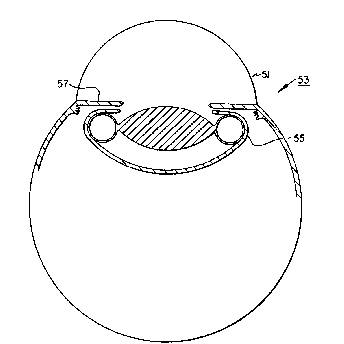
volume of the implant 21 thereby permitting implantation
through an incision size (Pormed through the cornea 51 o~
the eye 53) determined primarily by the dimensions and
volume Q~ the optic. once inside the eye, tlle implant is
intended to be positioned entirely within the capsular bag
55 (behind the
iris 57), where the haptic is then in~lated for fixation and
centration of the optic (Fig. 5). Therefore, it can be seen
that the entire implant, comprised of the central non-
inflatable and non-expandable optic and surrounding
in~latable haptic member (in its uninflated condition), will
be implantable through a very small incision. Further, as
mentioned, the problems with optic quality 'are totally
avoided. Therefore, a lens o~ high and unvarying optical
quality with small incision implantation capability is
provided.
The haptic member 31 is inflated by injecting a
suitably biocompatible fluid, which preferably is a liquid
or other flowable liquid-like material but which may be a
gas, into the chamber 35 whlch is ultimately defined and
limited by the distensibility o~ the material comprising the
:. . . . ..
2~6712
haptic cavity wall 33. The injected fluid-lik~ material or
liquid may or may not develop a certai~ fixed shape or
"harden". It can be seen that requirements o~ such a
fluid-like material are considerably less ~tringent than
requirements for materials which are injected into an optic
space. That is to say, the biological properties of a
fluid-like material which is iniected into a haptic space
are not as demanding as the biological properties o~ a
material injected into an optic space and therefore are not
as dif~icult to develop.
The fluid-like material may be injected into the
inflatable haptic space 35 through the small conduit 39 with
the aid of a small tubular needle with the one-way valve 41
allowing fluid flow in only one direction (toward the haptic
chamber only~ (Fig. 6). The material is injected until the
haptic chamber is seen to be completely distended and the
optic appropriately centered. In one embodiment, the
one-way valve 41 may be of the type disclosed in U.S. Patent
No. 4,585,457, althouyh other types of one-way valves may be
used. Another mechanism for preventing mat.erial leakage is
to employ only the conduit 39 and to seal its opening by
heat, glue or other means after injection is completed. In
an alternative, the conduit 39 may not be employed and a
sharp injection needle used to pierce the wall of the haptic
to inject the fluid into the space 35 after which the needle
is withdrawn and the opening sealed by heat or'glue. Also
the haptic may be ~ormed of a silicone type material such
that the opening ~ormed by the needle becomes self-sealing.
The wall of the inflatable haptic member is constructed of a
thin, "foldabl~" or pliable material which may be an elastic
or resilient material which defines the outer dimensions and
configuration of the inflatable haptic member upon injection
of a suitable biocompatible material. The wall material of
the haptic member is nonpermeable to the injection material
;, ~ .
~g~06t7 ~L~
_~ 8
to prevent leakage of the injection material through the
wall and into the eye.
In the preferred embodiment, the configuration of the
haptic member 31 is generally annular such that the central
optic 23 is surrounded 360 degree peripherally and
circumferentially by the haptic member 31 which when
inflated is in the shape somewhat like that of an inflated
inner tube. This will then give a complete circumferential
type of contact between the haptic and the outer tissue (the
lens capsule when placed within the cap~ular bag) which is
recognized to be probably the most secure and desirable type
of intraocular lens fixation attainable. The cross-
sectional area of the inflated space 35 may be generally
circular (Fig. 4), although it may vary considerably from
this general con~iguration, particularly in decreasing the
anterior/posterior dimension, while maintainillg the radial
dimen~ion. Approximate dimensions for a pre~erred
embodiment of the implant 21 comprises an optic measuring
approximately 6 to 7 mm. in diameter, with the haptic cavity
inflatable to give an overall diameter of the insert 21 of
approximately 10-13 mm. It is to be understood that the
implant 21 may have different dimensions.
In one embodiment, the optic 23 may be formed of
polymethylemethacrylate or other suitable materials such as
a foldable silicone-like material that will return to its
original unfolded shape after it is released fromlits folded
condition. The optic 23 may be circular or oval in shape.
Folding of the optic member may be desirable in
order to ~urther minimiæe the size of the incision in the
cornea. The haptic member 31 may be formed of a suitable
silicone or silicone-like elastomers. The optic 23 and the
haptic member 31 may be formed initially separately and the
haptic member 31 located around the outer periphery 27 of
the optic 23 and bonded or attached to the outer periphery.
~o~
:` 9 `:
The fluid employed to inflate the haptic member 31 may be
solutions of physiologic salts (index 1.33 to 1.44) and
Dertran (index 1.39 to 1.4) or a polymeric material such as
a Silastic as disclosed in U.S. Patent No. 4,585,457. Other
fluid type materials that may be employed to inflate the
haptic member 31 are disclosed in U.S. Patent: No. 4,693,717.
Referring to Fiqs~ 7-lo, the intraocular implant 21 of
Figs. 1-6 has been modified in that instead of having a
single inflatable haptic member 31, two separate inflatable
haptic members 3lA and 3lB are bonded to the periphery 27 of
the optic member 23 such that they are separated by spaces
31S. Each haptic member 31A and 31B is formed of the same
material as haptic member 31 and has a cavity 35 into with a
fluid, of the type mentioned above, may be injected to
inflate the two haptic members 31A and 31B, after the
implant 31 i5 implanted into the eye as descrlbed above.
Each haptic member 31A and 31B may have conduit 39 and a
one way valve 41, as described above, through which the
fluid may be injected into the cavity thereof for expansion
of the members 31A and 31B. In the alternative, each haptic
rnember 31A and 31B may have only a conduit 39 as described
above, through which the fluid may ~e injected and its
opening sealed after the injection is completed. As a
further alternative an injection needle may be employed to
pierce the wall of the haptic to inject the fluid and heat,
glue, or self-sealing haptic material employed to seal the
opening formed by the needle as described above.
The advantage of having at least two inflatable haptic
members 31A and 31B is that folding thereof may be easier
during implantation. In addition, if the fluid to be
injected is the type that "hardens", the use of two separate
inflatable haptic members 31A and 31B has advantages, in
that since each cavity is smaller than the cavity of haptic
member 31, each cavity of haptic members 3lA and 3lB may be
)67~2
filed quicker, thereby minimizing any problems o~
"hardening" of the fluid occurring before the smaller
cavities are ~illed.
Referring now to Figs. 11-13 of the drawings, the
intraocular implant of this embodiment is identified at 121.
It comprises a solid, non-inflatable, non-expandable,
transparent optic member 123, similar to that of member 23,
having a central axis 125 and an outer periphery 127. The
member 123 is circular or oval in plan view as is optic
member 23. Coupled to and circumferentially surrounding the
outer periphery 127 of the optic member 123 is a solid
haptic member 131. The optic member 123 is surrounded 360
degree peripherically and circumperentially by the haptic
member 131. The haptic member 131 is formed of a material
capable of combining with or taking up water from the
a~ueous of the eye result~ng in expansion of the haptic
member after insertion into the eye for enga~ing tissue of
the e~e (the capillary bag) ~or supportin~ the optic member
123 in the desired position in the eye.
The haptic member 131 may be formed in its generally
annular shape and then bonded to the outer periphery of the
optic 123. In the alternative, as shown in Figs. 14-16, the
haptic may comprise two separate arc-shaped solid members
131A and 131B each having a plan view similar to that o~
members 31A and 31B and which are bonded to the outer
periphery 127 of optic 123 as members 31A and 31B are
bonded to optic 23 such that members 131A and 131B are
separated by spaaes 131S.
Suitable materials that the haptic member 131 and
haptic members ~31A and 131B may be formed of are disclosed
in U. S. Patent Nos. 4,556,998, 4,734,095, 4,710,194 and
4,449,257 which are incorporated herein by reerence. In
the preferred embodiment the haptic member 131 and two arc-
shaped solid haptic members 131A and 131B are formed of the
` 2~06~Z
. 11 -
.
material identified in U. S. Patent No. 4,449,257 as
Hydroxyethyl Methacrylate abbreviated as HEMA. Since the
haptic members 131 and 131A and 131B are in the dry state
when the implant 121 is inserted into the eye the members
131 or 131A and 131B may not be folded relative to the optic
123 during the implantation process. Once lnside the eye,
the implant is intended to be positioned entirely within the
capular bag 55 (behind the iris 57). In this position,
over a period of time, the liquid from the aqueous of the
eye will combine with or be taken up by the material of the
haptic member 131 (or the two arc shaped solid haptic
members 131A and 131B) causing it (them) to expand and
engage the inside of the capsular bag and position and
support the optic 123 in the desired position in the eye.
The optic 123 may be formed of the same material as is
optic 23. In the embodiment of Figs. 11-16, the optic 123
may be formed of a foldable material that will return to its
orlginal un~olded shape a~ter it is released from its folded
condition. Folding of the optic member 123 may be desirable
in order to further minimize the size of the incision in the
cornea.
The haptic members 31A and 31B and 131A and 131B may
havs shapes different from that shown. In addition, more
than two inflatable haptic members may be coupled to the
periphery o~ ~he optic 23 and more than two solid liquid
expandable haptic members may be coupled to the'periphery of
the optic 123.
In summary, a unique intraocular lens design
incorporating a central non-expandable optic having attached
to its periphery an expandable haptic member (or haptic
members) which fixates and centers the optic within the eye
(within the capsular bag) is provided. The implant is
inserted into the eye with its haptic in its unexpanded
configuration to minimize insertion wound size requirements,
20~)6~
12
and then the haptic member or members is (are) expanded in
the first embodiment by injection of a suitable
biocompatible material into the haptic once the i~plant is
positioned loosely but completely within the capsular bag
and in the second embodiment by liquid uptake from the
aqueous of the eye. This new design avoids the problems of
optical quality inherent in any design in which the optic is
inflated or expanded, yet still possesses the desirable
features of a small incision lens with excellent fixation
characteristics. This design solution to small incision
implants provides a safer and more practical solution than
those inflatable or expandable designs which involve the
optic.