Note: Descriptions are shown in the official language in which they were submitted.
HOEC~ST ~TIENGESELLSC~L~FT HOE 88tF 385 Dr. ~R~9
Description
Fine-grained pol~ether-ketone lpowder~ pro~e~ iEor the
3nanuiEa~cture thereof r ~d th~ u~5e ~hereof .
The invention relates to a fine~grained polyether-ketone,
to the manufacture thereof in a fluid-bed opposed-~ets
mill and to the use of ~he powder especi~lly or produc-
ing surface coatings.
Polye~her-Xetones are polymers which are obtained by
nucleophilic or electrophilic condensation. They have
been described axtensively in an extremely large numher
of variations both with respect to their structure, their
preparation and their properties and possible applica-
tions. The polyether-ketones are highly esteemed by
those skilled in the art~ in particular because of their
outstanding property pattern. They are high t~mperature-
resistant, have very good mechanical propertieY and are
extremely resistant to chemical and environmental in-
fluences. They have the disadvantage, however, that it
is difficult to obtain them as a finely grained powder.
It is therefore also impossible to obtain crack-free,
uniform and, in particular, smooth coatings, for example
coatings on metal surfaces, hy means of flame-coating.
However, the known polyether-ketone powders or ~xains are
frequently also insufficiently fine for other pxocesses
and purpose~ such as, for example, electrostatic ~pray-
coating, whirl-sintering, ram e~trusion, the production
of pressed composites and the like. Some of the known
powders are also acicular and therefore tend to felting.
Recently, a process for pulverizing PEE~ has been dis-
closed, which is said to allow the production of powders
having a 97 ~ content of grain sizes of less than 20 ~m
("Plastics Engineering", 44 (1988) issue No. 9~ page 63).
Our owql tests have shown, however, that the data giYen
therein are insufficient for repeating the process or
~O~g~
obtaining a powder of this fineness.
The commercially available polyether-ketones ~U~:CTREX
PEEK 150 and VICTRBX PE~K 450 PF have grain 8iZQ8 of
about 100 ~m. Howe~er, ~he si~e of the grain and the
relatively wide grain size distribution of these products
are disadvantageous. No sati~factory results are there-
fore obtained in the powder-coating of metal~ or in
sintering processes.
It is the ob~ect of the invention to overcome the di~ad-
~antage~ mentioned and ~o provide a fine-grained poly-
ether-ketone powder having enhanced ~phericity an~d a
process for the manufacture thereof.
A fur~her ob~ect is to obtain a granulated polyether-
ketone powder which i8 largely free of abrasion by the
grinding device. ~hi~ is particularly important for a
faultlesY surface quality of the coatings.
The invention rela~es ~ a fine-grained polyether-ketone
powder which has a mean grain ~ize ~d50 v~lue) ~maller
than or equal ~o 40 ~m, preferably smaller than or equal
to 30 ~m and especially ~maller than or equal to 20~m.
Further data which are important for characterizing the
powder are the d90 value which i~ smaller than or equal to
70 ~m, preferably smaller than or equal to 50 ~m, and the
dlo value which is smaller than or equal to 15 ~m, prefer-
ably smaller than or equal to 10 ym. This give~ thedistribution range, which can be calculated from the
difference d30 minus dlo- It has values of smaller than or
equal to 55 ~m, preferably smaller than or equal to 40 ~m
and especially smailer than or equal to 20 ~m. The
distribution range defines the range of the grain size
distribution in the powders; the smaller the value, the
better is the processability and hence the structure of
the molding obtained.
The term polyether-Xetones includes all polymers which
have recurring units ~ ~ - O - ~ and ( ~ - CO - ). These
2~
units are mutually linked in ~arious ways, in general in
the p-position. Accord.ing to g~neral parlance, thP first
unit i5 designa~ed as E' (ether) and the second unit a~
~K (ketone). Thus, ~he abovemen~ioned polye~her-Xetone
is de6cribed as PEER. Pre~erred polyether-ketones
accordin~ to the invention are those of the PER and PERK
type~, and PEEK~ is particularly preferred. However,
these polymers can al~o con~ain other recurring units as
copolymer constituents, æelected from the group compri-
10 ~ing E~EE~, EÆR, EEKR, and EXR, but as a rule in quan-
tities of not more than 40 %, preferably not more than
20 % and particularly preferably not more than 5 mol ~.
With a view to the ver~atile applicability of the poly-
ether-ketone powder according to the present invention,
the powders can h~ve a melt index MFI from 400 to 1.0 g,
measured at 400C in 10 minutes ~ASTM D 1238). Their
melting point is in general above 250C, preferably above
300C and especially above 350C, and their softening
point is in general above 130C.
Moreover, the invention also re.lates to a process for
producing the ~ine-grained polyethex-ketone powder%, in
which coarse-grain polyether-ketone i5 cold-ground in a
fluid-bed opposed-~ets mill having a grinding chamber t2)
sub~ected to gas ~ets, a grinding material-charging
device, a ~creening device (5) for separating cn~r~e
material (11) and fine material (lO) t and a bottom (3)
underneath the grinding chamber for added material to be
ground and coa.rse material flowing back from the screen-
ing device, the material to be ground and the coarse
material ~lowing back from the screening device being
cooled by means of a cryogenic refrigerant~
Jet mills are comminuting machines known for a long time,
in which the particles to be comminuted are accelerated
by gas streams and comminuted by mutual Lmpingement.
' There are a number of different ~et mill designs. They
differ in the type of ga6 flow, in the type of
4 200
impingement of the particles on one another or on an
impingement ~urface and in whether ~he par~icles to be
comminuted are carri~d along in the gas ~t or whe her
the gas ~e~ ~npinges upon the particles and en~rains
S them. ~he grinding g~s use~ is normally air or ~uper-
heat~d steam.
In the fluid-bed opposed-jet~ mill, freely expanding gas
jet~ impact upon one another in a grindinq chamber which
contains the grinding material in the form of a fluid
bedO Grinding ~akes place here virtually exclusively by
mutual impingement of the grinding material particles
upon one another, and grinding is therefore almost free
of wear. The fluid-bed opposed-jets mill i8 associated
with a screening device in which the fines obtained are
~eparated off from the coaræe material which ha~ not yet
heen sufficiently comminuted. The coarse material is
returned into the gxinding chamber.
Many materials, for example, plastics, can be ground to
fine grain sizes only with difiEiculty or not at all,
becau~e of their toughnes~. The grinding properties of
~uch tough materials can be improved by cooling, which
results in an embrittlement of the material~. The
propellant gas ~tream in jet mills i~ therefore cooledt
as is described, for example, in German O~fenlegungs-
schrift 2,133,019. Cooling of the propellant gas ~tream
allows materials to be ground which will not be grindable
in ~et mills under normal conditions. In spite of
intensive cooling, for e~ample with liguid nitrogen, and
in spite of the cooling of the pxopellant gas stream
itself due t~ its exp~n~ion, the achievable Lmprovement
in grindability ~till, however, leave~ m~ch to be
desired. Fine grain sizes can admittedly be reached, but
only with extremely high Gonsumption of tLme and enexgy.
The proce s according to the invention therefore achieves
' the object of allowing super-fine grinding of polyether-
ketones to hitherto virtually unattainable very fine
- 5 ~ i9~'~
grain sizes with a substantial increa~e in throughput,
coupled with a low consumption of eneryy and refrigerant.
In this case, it is no~ the propellan~ gas stream, but
the circulating coars~ matexial which is cooled by a
cryogenic refrigerant. The measure according ko the
invention has the efect of a step change in ~mproving
the results of grinding, as can be ~een from the re~ults
listed in the table.
By means of the process according to the inven ion, a
considerable increase in throughput as compared with
grinding under normal conditions can be achieved in
fluid-bed opposed-~ets mills. Particles of highest
fineness with a corre6ponding increase in surface area
and a smooth curface structure can be produced ~-ith
polyether-ketones. The end product becomes readily
flowable and has a high bulk density and tap density.
The refrigerants used can above all be liquefied gases,
in particular nitrogen, but also carbon dioxicle. In the
simplest and frequently most appropriate case, these can
be fed directly into the bot~om o~E the mill. Of course,
indirect cooling of the coarse material is also possible.
Indirect cooling can also be effected by other refriger-
ants, for example brine baths.
A few illustrative examples of the invenkion will be
explained by reference to the attached drawings, in
which:
Figure 1 shows a fluid-bed opposed-jets mill in a
diagrammatic fonm,
Figure 2 shows the coolinq of the bottom of the fluid-
bed opposed-~ets mill of Figure 1,
Figure 3 shows a mixed f~rm of direct and indirect
cooling of the bottom,
Figure 4 show~ an embodiment similar to Figure 3, but
exclusively with direct cooling,5 ~ Figure 5 shows direct cooling of the coarse material
flowing back outside of the bottom of the mill/
- 6
and
Figure 6 ~hows indirect cooling of the coar~e material
flowing back outside o the bottom of the mill.
In the description which follows, the same reference
symbols ha~e been used in all figures for the s~me parts.
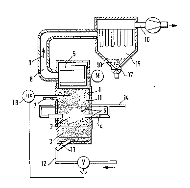
Figure 1 shows th~ fluid-bed opposed-jets mill in a
diagra~ma~ic form. The mill comprises a housing 1 which
contains the grinding chamber 2 and the bottom 3. The
propellant gas enters the grinding chamber 2 through the
nozzles 4. The hou~ing 1 i5 ad~oined by the ~creening
~evice 5. The coarse material to be ground is in the
form of a fluid bed 6 in the yrinding chamber. The
grinding material is fed in through the lock 7. The
fines 10 separated off in the screening device 5 are
withdrawn through the fines outlet 8, as indicated ~y the
arrow 9, and fed to the filter unit 15. The latter
possesses a branch 16 for the exit gas and a discharge
lock 17 for the fines 10 produced. The coar~e material
11 flows from the screening device 5 baclc into the
grinding chamber 2. The propellant gas charged to the
nozzles 4 is introduced through t.he feed line 14.
According to the invention, the l~oarse material present
in the bottom 3 of the mill is cooled down by liquid
nitrogen. The lat~er is introduced through ~he line 12
and the porou~ charging body 13. Porous charging bodies
are particularly suit~ble for ~mall mills. ~or mills of
larger diameters, other charging systems, for e~mple
nozzle plates, are to be preferred, in order to enable
the nitrogen to be introduced a~ finely di~ided a~
possible. The nitrogen feed through the line 12 and the
porous charging body 13 takes place as a function of the
temperature control 18. The charging of the grinding
material t~rough the lvck 7 can also take place direc~ly
in~o the bottom 3. The fines fraction of the fine
~ material 10 is determined by the spQed of rotation of the
screening device 5. The coar~e material 11 flowing back
9~'~
-- 7 --
from the ~creening device 5 together with the grinding
material entering from the lock 7 forms the fluid bed 6.
The liquid nitrogen entering through the porous charging
body 13 vaporizes and cools the bottom of the mill, i.e.
the coaræe material 11 flowing back from the screening
device 5 and any freshly charged grinding material. The
vaporized cold ni~rogen flows of upwards thxough the
material and enters ~he grinding zone. Cold gas, coarse
material and grinding material form a first fluid-bed
zone underneath the grinding ch~mber 2 in the bottom 3.
Figure 2 shows the lower part of the fluid-bed opposed-
jets mill of Figure 1 in a diagrammatic ~orm, but with
the lock 7 for the grinding material located directly on
the bottom 3. The arrows 19 clearly indi~te the mixture
of cold gas, propellant gas, coarse material and fine
material flowing upwards to the screening device.
Figure 3 ~hows a variant with indirect and direct heat
exchange between the nitrogen feed and grindîng material.
The liguid nitrogen i~ fed through the lines 20 and 21.
The liquid nitrogen entering through line 21 passe~ into
a double-walled pipe 22 closed at the end faces. Thi~
double-walled pipe 22 has inward-E)ointing outlet orifices
23. The entire lower part of the mill housing is like-
wise constructed as a double-walled chamber 24. The line
20 leads into the latter. The chamber 24 has outlet
orifices 25, arranged in the bottom 3, for the nitrogen
fed through the line 20. The coarse material 11 flowing
back from the screening device is thexefore first cooled
indirectly in the region between the doubled-walled tube
22 and the chamber 24. Subseguently, direc~ cooling
taXes place by the nitrogen isæuing from the outlet
orifice~ 23 and 25.
Depending on the mode of operation, this nitrogen can be
still liquid or already gaseous.
Figure 4 show~ another embodLment similar to Figure 2,
oo
but with an ex~ended bottom 3. A certain type o flow
is here impressed upon the coarsP material 11 and the
cold ga~ by a pipe-shaped apron 26. The apron 26 separ-
ates the grinding chamber into a central shaft 37, where
the grinding process takes place, and an annular shaft 38
for the coarse material flowing back. Liquid nitrogen
feed takes place at two points, namely through line 12a
directly into the bottom 3 and through line 12b into a
spray system 39 in the annular shaft 3B. Accordingly~
the nitrogen introduced through line 12b directly cools
the coarse material flowing back from the screening
device.
Figure 5 shQws a Yariant with direct but extPrnal heat
exchange between refrigerant and coarse material. The
coarse material separated off in the externally arranged
~creening device 5 passes through the line 27 into the
filter 28. The exit gas escapes through line 29, while
th2 coarse material together with any grinding material
added through the line 30 enters a helical screw 31.
Liguid nitrogen entering through the line 32 i8 fed to
the helical ~crew 31. The mixture of cooled c~arse
material and vaporized nitrogen flows through line 33
into the bottom 3.
Figure 6 shows a variant of the embodiment according ~o
Figure 5. The coarse material from the filter 28 and any
grinding material fr~m the line 30 here enter a heat
ex~h~nger 35. From there, they pass indirectly cooled
into the bottom 3. The cooling is effected by liquid
nitrogen which i8 introduced through line 34 in~o the
h~at exchanger 35. Vapori2ed ga~eous nitrogen then
passes as cold gas through the line 36 likewise into the
bottom 3, where subsequent fur~her direct cooling takes
place.
There are still numexou~ further possibilities for
' cooling the coarse material flowing back from he
screening device by a refrigerant. For example, a
- 9 ~
plurality of grinding zones with a bottom can be arranged
in series in the form of a cascade. In this case, the
mix~ure of fines and coarse material leaving the grindiny
zone is separated from ~he exit ga~ in the filter and fed
to the ne~t grinding zone. The bo~tom located underneath
sach grinding zone i6 here cooled according to the
invention. A screening device is associated onl~ wi h
the last staye.
The fine-grained polyether ketones according ~o the
invention can advantageously be used for coating sur-
faces, for example by flame-coating, electrostatic spray-
coating, whirl-sintering or ram extrusion. Furthermsre,
they are outstandinyly suitable for sintering processes,
for example for producing pressed composites.
Examples:
As the start~ng point for the tests, a polyether-ether-
ketone-ketone (PEEKK) having a melt index MPI of 15 g
~400C/10 min) was used. The particle sizes of this
starting material are listed in t]he table. Moreover, two
commercially available polyether-ketones from ICI under
the names ~Victrex PEEK 150 P and Victrex PEEK 450 PF (Vl
and V4 and V5 respectively) were used as a comparison.
Examples 2 and 3 represent ex~mples according to the
invention.
The particle size analysi6 was carried out on a suspen-
sion of solid, water and wetting agent ~a~ed on
nonylphenol polyglycol ether, using a commercially
available laser granulometer (Manufacturer: Cilas, 91460
Marcousse, France). The dlo, d50 and d~o values were chosen
as repres~ntative value6. For example, the dlo value of
~.4 ~m in Example 2 means that 10 ~ of the end produc~
have a particle size of 6.~ ~m. Examples 2 and 3 differ
in this respect to the speed of rotation of the screening
-' device and the product throughput rate.
i9(~'~
--10--
o
U~ o ~ ~ C`~
U~
E~
H
p
o
U~
_I
O O 0
O
S~
H
~4 . . . .
~ ~ C: CO O t`I` ~D O C~_I ~ ~ O
t~ ~ r-lO CD_~ I
o a~ n ~ o o
~ ~~ ~ '~
E~
P~ ~
P ~ I I~ _l
-
a) -- ~
h
~3 .4
O ~ ~
oC~) 0
O ~
o~ ,1 rl ~s ~ h
1 0 al tD rl N S:~ -- 0
_t ~ O .C h ~ 1 0 ~3 E3
h ~ ~ ~ ~ ,1 0
O
~D ~ Q O ~ .4
rl O -~ Y
~a o N N (D ~ M O ~ ~
o o ~ ta ~ ~ 0 S~ ~ O d 2 cn ~
æ z ~ h ~ rcl ~ ~ a ~ *
9~
The table ~hows that ~he distl-ibution range decreases
when the ~peed o rotation of the screening devics
increases and the product throughput decreases, i.e. a
product having a uniform particle size properties is
obtained in Example 2. A further advantage of these
polyether~ketone powders i8 the l~rgely spheroidal form
of the PE~ paxticles. The increased sphericity of the
particles leads to an improved flowability as compared
with the hitherto known processes. The flowability is
important for uniform application in use, for example in
metal coating. Due to the agglomeration tendency of the
known powders, non-uniform ~urfaces can result from the
hitherto known grinding proce6ses. However, a uniform
suxface is a prerequisite for ~he quality of ~he surface.
Hitherto, only crazed surfaces were obtainable, wherea~
smooth suxfaces are obtained with the polyether-ketone
powders ac:cording to the invention.