Note: Descriptions are shown in the official language in which they were submitted.
Z(~6993
~E-3905
THERMAL SPRAY METHOD FOR PRODUCING GLASS MOLD PLUNGERS
This invention relates to glass mold plungers and particularly to
a method for producing glass mold plungers utilizing thermal
spraying.
~ACKGROUND OF THE INVENTION
Thermal spraying, al60 known as flame spraying, involves the
melting or at least heat softening of a heat fusible material
such as metal or ceramic, and propelling the softened material in
particulate form against a surface which is to be coated. The
heated particles strike the surface where they are quenched and
bonded thereto. A thermal spray gun such as described in U.S.
Patent No. 3,455,510 (Rotolico) is used for the purpose of
heating and propelling the particles. In this type of thermal
spray gun, the heat fusible material is 6upplied to the gun in
powder form. Such powders are comprised typically of small
particles, e.g., between 100 mesh U. S. Standard screen size (149
microns) and about 2 microns. Heat for powder spraying is
generally from a combustion flame or an arc-generated plasma
flame. The carrier gas, which entrains and transports the
powder, may be one of the combustion gases or an inert gas such
as nitrogen, or it simply may be compressed air.
Quality coatings of certain thermal spray materials have been
produced by spraying at high velocity. Plasma spraying has
proven successful with high velocity in many respects but it can
suffer from non-uniform heating and/or poor particle entrainment
which must be effected by feeding powder laterally into the high
velocity plasma stream.
,~ ' ,
6993
ME-3905
Rocket types of powder spray guns recently became practical and
are typified in U.S. Patent No. 4,416,421 (Browning). This type
of gun has an internal combustion chamber with a high pressure
combustion effluent directed through a nozzle or open channel.
Powder i6 fed into the nozzle chamber to be heated and propelled
by the combustlon effluent.
Short-nozzle spray devices are disclosed for high velocity
spraying in French Patent No. 1,041,056 and U.S. Patent No.
2,317,173 (Bleakley). Powder is fed axially into a melting
chamber within an annular flow of combustion gas. An annular air
flow is injected coaxially outside of the combustion gas flow,
along the wall of the chamber. The spray stream with the heated
powder issueæ from the open end of the combustion chamber.
Sprayweld alloys of the boron-silicon-nickel type are known in
the art, and comprise a nickel base to which is added relatively
small percentages of boron and silicon to improve the fluxing
characteristics of the nickel base alloy. Other elements, such
as chromium, are frequently included in nickel base alloys of
this type.
Such alloys are used for welding and brazing and particularly for
coating materials applied a6 a fused or welded over-lay on base
materials, such as steel or steel alloys. The elements boron and
silicon, when added to nickel or nickel base alloys, act as
fluxer of the alloy and of the surface to be alloyed during the
fusing of the alloy when performing the brazing, welding or
coating operation. For this reason such alloys are known as
~self-fluxing alloys~.
2~)06993
ME-3905
One process frequently used for applying fused coatings of boron-
silicon-nickel alloys is known as ~spray-welding~. Spray-welding
comprises the steps of first metal spraying the alloy onto the
surface to be coated such as with a combustion powder spray gun
5 of the type disclo6ed in the aforementioned U.S. Patent No.
3,455,510, and second, fusing the coating in place. The metal
6praying operation can be carried out by any of the known metal
spraying techniques, in which the material to be sprayed is fed
into a heating zone where it is melted or heat-softened and from
10 which it is, in finely divided form, propelled in molten or heat-
plastic condition onto the surface to be coated. After coating6
have been applied by the metal spraying process, they are
thereafter fused in the carrying out of the spray-welding
process. Such fusing may be done in a furnace or,
15 alternatively, by means of heating torches applied directly to
the coated surface. Self-fluxing alloys and typical compositions
are described in more detail in U.S. Patent No. 2,875,043 (Tour).
Although fused coatings of self-fluxing alloys are quite wear
20 resistant per se, further wear resistance is gained by blending
hard particles such as a carbide powder with the alloy powder
prior to spraying. Such a carbide generally includes a metal
binder, such as tungsten carbide $n a cobalt matrix as disclosed
in British Patent No. 867,455. Fused thermal sprayed
25 self-fluxing alloy coatings, with or without carbide, are
susceptible of being ground and polished to a very high finish.
A particular application requiring the wear resi6tance and finish
of such coatings is the production of glass mold plungers. In
30 the manufacture of glass objects such as bottles an early step is
to inject a heated rod-shaped plunger into a small mass of heat
softened glass to produce an initial hole therein. The glass is
.,- -.-,;
, ' ' .
.
Z(~)6993
ME-3905
thereafter blown into shape with compressed air applied into the
hole. It is critical that the plunger have a smooth shape and a
high, mirror-like finish in order to prevent flaws from
developing in the glass objects. Even a small imperfection in
the plunger surface picks up glass to form larger imperfections
in subsequent operations with the plunger.
Because of wear and finish capability, thermal spraying has been
u6ed for many years for making and refurbishing glass mold
plungers. U.S. Patent No. 4,382,811 (Luscher et al.) teaches
such utilization. Although oxide powder blended with the
self-fluxing alloy is taught therein, self-fluxing alloy with or
without carbide is much more commonly used on plungers.
~owever, a continuing problem is that it iB quite difficult and
technique dependent to thermal spray and fuse coatings onto glass
mold plungers without flaws. Spray parameters are critical,
requiring close control of gas flows, spray distance, traverse
rates, spray speed and temperature control. Also, in finishing
the coating, the tapered shape of the plunger results in
overheating of the tip of the plunger. As a result only certain
operators are sufficiently proficient to do the job, 80 it iB
expensive and has a high reject rate.
Therefore, objects of the present invention are to provide an
improved method of manufacture of glass mold plungers, to provide
an improved thermal spray method for manufacturing glass mold
plungers, and to provide for the manufacture of glass mold
plunger6 with reduced technique dependence, rejection rate and
cost.
. .
~'~V~g93
ME-3905
SUMMARY OF THE INVENTION
The foregoing and other objects are achieved by a method for
manufacturing a glass mold plunger utilizing a thermal spray gun
S having combustion chamber means therein with a combustion chamber
and an open channel for propelling combustion products into the
ambient atmosphere at supersonic velocity. The method comprises
preparing a glass mold plunger substrate for receiving a thermal
sprayed coating, feeding through the open channel a powder
comprising self-fluxing alloy particles, injecting into the
chamber and combusting therein a combustible mixture of
combustion gas and oxygen at a pressure in the chamber sufficient
to produce a supersonic spray stream containing the powder
issuing through the open channel, directing the spray stream
toward the glass mold plunger substrate such as to produce a
coating thereon, and grind finishing the coating to a polished
finish.
A preferred the self-fluxing alloy consists essentially of about
10% to 18% chromium, 2% to 4% boron, up to 4% silicon, up to a
total of 9% of one or more of molybdenum, copper, iron and
tungsten, 0.15% to 1.0% carbon, balance nickel and or cobalt.
In a further embodiment the powder is a blend consisting
essentially of the self-fluxing alloy particles and carbide
particles. The carbide particles preferably constitute about 30%
to 70% by weight of the blend and consist essentially of -5
micron tungsten carbide subparticles in a cobalt matrix. The
cobalt constitutes about 12~ to 20% by weight o$ the total of the
tungsten carbide and the cobalt.
In a particular embodiment the thermal spray gun includes a
nozzle member with a nozzle face and a tubular gas cap extending
2()~6993
ME-3905
from the nozzle member these caps having an inwardly facing
cylindrical wall defining a combustion chamber with an open end
and an opposite end bounded by the nozzle face. The method then
comprises the steps of preparing a glass mold plunger substrate
S for receiving a thermal sprayed coating, injecting an annular
flow of a combustible mixture of a combustion gas and oxygen from
the nozzle coaxially into the combustion chamber at a pressure
therein of at least two bar above atmospheric pressure, injecting
an annular outer flow of pressurized non-combustible gas adjacent
to the cylindrical wall radially outward of the annular flow of
the combustible mixture, feeding a powder comprising particles
having heat stable non-meltable cores and heat softenable
surfaces in a carrier gas axially from the nozzle into the
combustion chamber, injecting an annular inner flow of
pressurized gas from the nozzle member into the combustion
chamber coaxially between the combustible mixture and the powder-
carrier gas, combusting the combustible mixture in the combustion
chamber whereby a supersonic spray stream containing the heat
fusible material in finely divided form is propelled through the
open end, directing the spray stream toward a substrate such as
to produce a coating thereon, and grind finishing the coating to
a polished finish.
BRIEF DESCRIPTION OF THE DRAWINGS
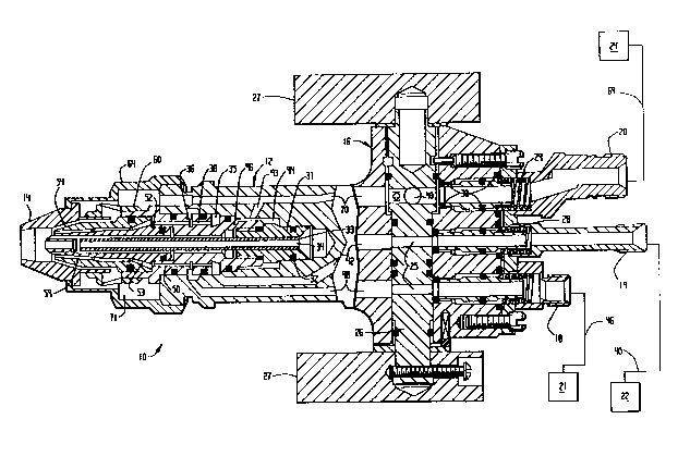
FIG. 1 i8 an elevation of a thermal spray gun used in the present
invention.
FIG. 2 is a section taken at 2-2 of FIG. 1.
FIG. 3 is an enlargement of the forward end of the section of
FIG. 2.
Z')~6993
ME-3905
FIG. 4 is a section taken at 4-4 of FIG. 1, and a schematic of an
associated powder feeding system.
FIG. 5 is a schematic view of the gun of ~IG. 1 producing a
supersonic spray stream according to the present invention.
FIG. 6 is the view of FIG. 5 with a substrate in place.
DETAILED DESCRIPTION OF THE INVENTION
An example of a preferred thermal spray apparatus for effecting
the present invention is disclosed in co-pending U.S. Patent
Application Serial No. 193,030 filed May 11, 1988, assigned to
the assignee of the present invention and detailed herein below.
The apparatus is illustrated in FIG. 1, and FIG. 2 shows a
horizontal section thereof. A thermal spray gun 10 has a gas
head 12 with a tubular member in the form of a gas cap 1~ mounted
thereon, a valve portion 16 for supplying fuel, oxygen and air to
the gas head, and a handle 17. The valve portion 16 ha~ a hose
connection 18 for a fuel gas, a hose connection 19 for oxygen and
a hose connection 20 for air. The three connections are connected
respectively by hoses from a fuel source 21, oxygen source 22 and
air source 2~. Orifices 25 in a cylindrical valve 26 control the
flow of the respective gases from their connections into the gun.
The valve and associated components are, for example, of the type
taught in U.S. Patent No. 3,530,892 (Charlop), and include a pair
of valve levers 27, and sealing means for each gas flow section
that include plungers 28, springs 29 and O-rings 30.
A cylindrical siphon plug 31 is fitted in a corresponding bore in
gas head 12, and a plurality of O-rings 32 thereon maintain a
gas-tight seal. The siphon plug is provided with a tube 33
;:')(~6993
ME-3905
having a central passage 3~. The siphon plug further has therein
an annular groove 35 and a further annular groove 36 with a
plurality of inter-connecting passages 38 (two shown). With
cylinder valve 26 in the open position as shown in FIG. 2, oxygen
is passed by means of a hose ~0 through its connection 19 and
valve 26 into a passage ~2 from whence it flows into groove 35
and through passage 38. A similar arrangement i8 provided to
pass fuel gas from source 21 and a hose ~6 through connection 18,
valve 26 and a passage ~8 into groove 36, mix with the oxygen,
and pass as a combustible mixture through passages 50 aligned
with passages 38 into an annular groove 52. Annular groove 52
feeds the mixture into a plurality of passages 53 in the rear
section of a nozzle member 5~.
Referring to FIG. 3 for details, nozzle member 5~ is conveniently
constructed of a tubular inner portion 55 and a tubular outer
portion 56. (As used herein and in the claims, ~inner~ denotes
toward the axis and ~outer~ denotes away from the axis. Also
~forward~ or ~forwardly~ denotes toward the open end of the gun;
~rear~, ~rearward~ or ~rearwardly~ denotes the opposite.) Outer
portion 56 defines an outer annular orifice means for injecting
the annular flow of the combustible mixture into the combustion
chamber. The orifice means preferably includes a forward annular
opening 57 with a radially inward side bounded by an outer wall
58 of the inner portion. The orifice system leading to the
annular opening from passages 53 may be a plurality of arcuately
spaced orifices, but preferably is an annular orifice 59.
The combustible mixture flowing from the aligned grooves 52 thus
passes through the orifice (or orifices) 59 to produce an annular
flow which is ignited in annular opening 57. A nozzle nut 60
holds nozzle 5~ and siphon plug 28 on gas head 12. Two further
V~993
ME-3905
0-rings 61 are seated conventionally between nozzle 5~ and siphon
plug 31 for gas tight seals. The burner nozzle 5~ extends into
gas cap 1~ which is held in place by means of a retainer ring 6
and extends forwardly from the nozzle.
Nozzle member 5~ is also provided with an axial bore 62, for the
powder in a carrier gas, extending forwardly from tube passage
33. Alternatively the powder may be injected through a small-
diameter ring of orifices (not shown) proximate the axis 63 of
the gun. With reference to FIG. 4 a diagonal passage 6~ extends
rearwardly from tube 33 to a powder connection 65. A carrier
hose 66 and, therefore, central bore 62, is receptive of powder
from a powder feeder 67 entrained in a carrier gas from a
pressurized gas source 68 such as compressed air by way of feed
hose 66. Powder feeder 67 is of the conventional or desired type
but must be capable of delivering the carrier gas at high enough
pressure to provide powder into the chamber 82 in gun 10.
With reference back to FIGS. 2 and 3, air or other non-
combustible gas is passed from source 2~ and a hose 69 through
its connection 20, cylinder valve 26, and a passage 70 to a space
71 in the interior of retainer ring 6~. Lateral openings 72 in
nozzle nut 60 communicate 6pace 71 with a cylindrical combustion
chamber 82 in gas cap 1~ ~o that the air may flow as an outer
sheath from space 71 through these lateral openings 72, thence
through an annular slot 8~ between the outer surface of nozzle
5~, and an inwardly facing cylindrical wall 86 defining
combustion chamber 82 into which slot 8~ exits. The flow
continues through chamber 82 as an annular outer flow mixing with
the inner flows, and out of the open channel at open end 88 in
gas cap 1~. Chamber 82 is bounded at its opposite, rearward end
by face 89 of nozzle 5~.
Z'~06993
ME-3905
Preferably combustion chamber 82 converges forwardly from the
nozzle at an angle with the axis, most preferably between about
2 and 10, e.g. 5. Slot 8~ also converges forwardly at an
angle with the axis, most preferably between about 12 and 16,
e.g. 14.5. Slot 84 further should have sufficient length for
the annular air flow to develop, e.g. comparable to chamber
length 102, but at least greater than half of such lengtb 102.
In addition, the chamber should converge at a lesser angle than
the slot, most preferably between about 8 and 12, e.g. 10
less. This configuration provides a converging air flow with
respect to the chamber to minimize powder buildup on the chamber
wall.
The air flow rate should be controlled upstream of slot 8~ such
as in a rearward narrow orifice 92 or with a separate flow
regulator. For example slot length i6 8 mm, slot width is 0.38
mm on a 15 mm circle, and air pressure to the gun (source 2~) is
4.9 kg/cm2 (70 psi) to produce a total air flow of 425 std l/min
(900 scfh) with a pressure of 4.2 kg/cm2 (60 psi) in chamber 82.
Also, with valve 26 in a liqhting position aligning bleeder holes
as described in aforementioned U.S. Patent No. 3,530,892, an air
hole 90 in valve 26 allows air flow for lighting, and the above-
indicated angles and dimensions are important to allow such
lighting without backfire. (Bleeder holes in valve 26 for oxygen
and fuel for lighting, similar to air hole 90, are not shown.)
The inner portion 55 of nozzle member 5~ has therein a plurality
of parallel inner orifices 91 (e.g. 8 orifices 0.89 mm diameter)
on a bolt circle (e.g. 2.57 mm diameter) which provide for an
annular inner sheath flow of gas, preferably air, about the
central powder feed issuing from bore 62 of the nozzle. This
inner sheath of air contributes significantly to reducing any
993
ME-3905
tendency of buildup of powder material on wall 86. The sheath
alr is conveniently tapped from passage 70, via a duct 93 (FIG.
2) to an annular groove 9~ around the rear portion of siphon plug
31 and at least one orifice 96 into an annular 6pace 98 adjacent
tube 33. Preferably at least three such orifices 96 are equally
spaced arcuately to provide sufficient air and to minimize vortex
flow which could detrimentally swirl the powder outwardly to wall
86 of chamber 82. The inner sheath air flow should be between 1%
and 10%, preferably about 2% and 5% of the outer sheath flow
rate, for example about 3%. The inner sheath may alternatively
be regulated independently of the outer sheath air, for better
control.
Chances of powder buildup are further minimized by having the
inner portion 55 of the nozzle member protrude into chamber 82
forwardly of the outer portion 56 as depicted in FIGS. 2 and 3.
A chamber length 102 may be defined as the shortest distance from
nozzle face 89 to open end 88, i.e. from the forwardmost point on
the nozzle to the open end. The forwardmost point on the inner
portion should protrude forwardly from the outer portion 56 by a
distance between about 10% and 40% of chamber length 102,
e.g.30%.
A preferred configuration for the inner portion is depicted in
FIGS. 2 and 3. Referring to the outer wall 58 of inner portion
55 of the nozzle, which defines annular opening 57, such wall 58
should extend forwardly from the annular opening with a curvature
inward toward the axis. The curvature should be uniform. For
example, as shown, the curvature is such as to define a generally
hemispherical face 89 on inner portion 58. It is believed that
the combustion flame is thereby drawn inwardly to maintain the
flows away from chamber wall 86.
11
Z'~)6993
ME-3905
As an example of further details of a thermal spray gun
incorporating the present invention, siphon plug 31 has 8 oxygen
passages 38 of 1.51 mm each to allow sufficient oxygen flow, and
1.51 mm diameter passages 50 for the gas mixture. In this gas
head central bore 62 is 3.6 mm diameter, and the open end 88 of
the gas cap is 0.95 cm from the face of the nozzle (length 102).
Thus the combustion chamber 82 that also entrains the powder is
relatively short, and generally should be between about one and
two times the diameter of open end 88.
A supply of each of the gases to the cylindrical combustion
chamber i8 provided at a sufficiently high pressure, e.g. at
least 30 psi above atmospheric, and is ignited conventionally
such as with a spark device, such that the mixture of combusted
gases and air will issue from the open end as a supersonic flow
entraining the powder. The heat of the combustion will at least
heat soften the powder material such as to deposit a coating onto
a substrate. Shock diamonds should be observable. Becaose of
the annular flow configuration, an expansion type of nozzle exit
is not necessary to achieve the supersonic flow.
The combustion gas may be propane or hydrogen or the like, but it
is preferable that the combustion gas be propylene gas, or
methylacetylene-propadiene gas (~MPS~). These latter gases allow
a relatively high velocity spray stream and excellent coatings to
be achieved without backfire. For example with a propylene or
MPS pressure of about 7 kg/cm2 gauge (above atmospheric pressure)
to the gun, oxygen at 10 kg/cm2 and air at 5.6 kg/cm2 at least 8
shock diamonds are readily visible in the spray stream without
powder flow. The appearance of these shock diamonds 108 in spray
stream 110 is illustrated in FIG. 5. The position of a glass
mold plunger substrate 112 on which a coating 11~ is sprayed is
12
~'~436993
ME-3905
preferably about where the fifth full diamond would be as shown
in FIG.6, e.g. about 9 cm spray distance. Preparation of the
substrate includes machining to size taking coating thickness
into account, and grit blasting the surface in the usual manner
to clean and roughen it. The 6ubstrate is cylindrical and is
rotated in a head stock while being coated.
According to the present invention a self-fluxing alloy is coated
onto a glass mold plunger substitute by supersonic combustion
thermal spraying, for example with a gun as described in
aforementioned U.S. Patent No. 4,416,421, but preferably with a
gun of the type detailed hereinabove for relative freedom from
internal buildup of coating material and other advantages as
outlined in aforementioned Application Serial No. 193,030. It
has been discovered that the coatings sprayed with high velocity
are so uniform and dense that, when polish finished, the surfaces
are virtually free of defects. It was further discovered,
surprisingly, that the high quality coatings could be achieved
with a substantial reduction in technique dependence and reject
rate over the prior thermal spray method.
Further, with high velocity it often is unneces6ary to
subsequently fuse the coating to achieve a flawless polish
finish, thus eliminating a step that has not only a significant
cost but it6 own technique dependence with a6sociated problems.
However if fusing is deemed neces6ary, it is achieved more easily
and requires les6 grinding because of the quality of the original
deposit. Fusing iR effected by conventional methods such as with
a flame torch or, preferably, a controlled furnace with a
reducing atmosphere.
;993
ME-3905
Coating thickness as sprayed i8 about .7 mm to 1.3 mm. Coating
removal by grinding i6 typically about 0.15 mm to 0.3 mm,
compared with 0.5 mm for prior art sprayed and fused coatings.
The self-fluxing alloy is conventionally of the types disclosed
in the aforementioned U.S. Patent No. 2,875,043 and British
Patent No. 867,455. A preferable type of alloy for coating glass
mold plungers consists essentially of about 10% to 18% chromium,
2~ to 4~ boron, up to 4~ silicon, up to a total of 9% of one or
more of molybdenum, copper, iron and tungsten, 0.15% to 1.0%
carbon, balance nickel and or cobalt to a total of 100%.
The self-fluxing alloy is used as-is but may be mixed with other
metals such as simple nickel chromium alloy, co~posite nickel-
aluminum powder or molybdenum to enhance fusing or other
characteristics.
For optimum wear resistance the self-fluxing alloy powder
particles should be blended with hard, non-metal particles such
as the oxide particles of the aforementioned U.S. Patent No.
4,382,811, a boride or a nitride, or a carbide such as nickel
bonded titanium carbide, or the like. Perfectly the hard
particles are carbide particles, which generally should be in the
range of about 30% to 70% by weight of the blend. More
preferably the carbide particles consist essentially of tungsten
carbide in a cobalt matrix and, for optimum finish, the tungsten
carbide is in the form of subparticles of substantially -5
microns in the cobalt matrix. Most preferably the subparticles
are about 1 to 2 microns. Such particles are produced by
sintering such subparticles with the cobalt which should
constitute about 12% to 20% by weight of the total of the
tungsten carbide and the cobalt. Alternatively the powder is
Z'~ 6993
ME-3905
produced by spray drying such as taught in U.S. Patent No.
3,617,358 (Dittrich).
ExamDle
A glass mold plunger substrate is machined from mild steel stock,
~ith a length of 12.7cm and an diameter of 2.5cm at its gripping
end tapered down to 1.3cm at its plunger end which is rounded.
The surface i8 prepared by grit blasting with G24/40 aluminum
oxide grit at 4.2kg/cm2 (60 psig) air pressure.
A powder blend similar to Metco 34F (except size) sold by The
Perkin-Elmer Corporation, Westbury, NY, i8 prepared consisting of
50S self-fluxing alloy and 50~ tungsten carbide/cobalt. The
alloy consists of 17~ chromium, 4~ iron, 3.5~ boron, 4% silicon,
1% carbon and balance nickel and incidental impurities (vis AMS
4775A alloy). Alloy powder size is - 53 + 10 microns. The
carbide i8 12~ cobalt bonded tungsten carbide, with subparticles
of about 1 to 2 microns manufactured by spray drying
substantially as taught in Example 1 of the aforementioned U.S.
Patent No. 3,617,358. Carbide size is -53 +10 microns.
The blend is sprayed with the preferred apparatus described above
~ith respect to FIGS. 1-3, specifically a Metco Type DJ(TM) Gun
sold by The Perkin-Elmer Corporation, Westbury, New York, usinq a
t3 insert, t3 injector, ~A~ shell, t2 siphon plug and t2 air cap.
Oxygen was 10.5 kg/cm2 (150 psig) and 212 l/min (450 scfh),
propylene gas at 7.0 kg/cm2 (100 psig) and 47 l/min (100 scfh),
and air at 5.3 kg/cm2 (75 psig) and 290 l/min (615 scfh). A high
pressure powder feeder of the type disclosed in the present
assignee's co-pending U.S. Patent Application Serial No.
filed October 21, 1988 tattorney docket ME-3881] and sold as a
;~U6993:
ME-3905
Metco Type DJP powder feeder by Perkin-Elmer is used to feed the
powder blend at 60 gm/min (8 lbs/hr) in a nitrogen carrier gas at
8.8 kg/cm2 (125 psig) and 7 l/min (15 scfh). Spray distance is
20 cm (8 inches).
The as-sprayed coating is ground conventionally with a diamond
wheel, and polished. Diamond wheels are used at 5500 surface
feet per minute (1675 m/min), rough grind with a 240 grit wheel,
size with a 400 grit wheel and finish with a 600 grit wheel. For
a lapped finish, diamond compound is used. (As used herein and
in the claims the term ~grind finishing~ includes all course and
fine grinding and polishing 6teps conventionally used to effect
the finish achievable on the coated surface.) A Dirror-like 5
micron aa finish is achieved. The resulting glass mold plunger
i8 excellent for its purpose.
ExamDle 2
Example 1 is repeated except that a spray distance of 25cm is
used. Similar results are achieved, demonstrating tolerance in
technique dependence.
ExamDle 3
Example 1 is repeated except that the as-sprayed is fused before
the grinding step. Fusing is effected in a furnace with a
hydrogen atmosphere at 1000 - 1075 C for 15 minutes. After
grinding and polishing the finish is 4 microns aa.
16
;2~)(36993
ME-3905
ExamDle 4
Example 1 is repeated except that the carbide is omitted from the
blend; i.e. neat self-fluxing alloy is used. A final surface
finish of 4 microns aa is achieved. Use for producing glass
objects is similar except that the life of the plunger is shorter
due to the greater wear of the neat alloy.
While the invention has been described above in detail with
reference to specific embodiments, various changes and
modifications which fall within the spirit of the invention and
scope of the appended claims will become apparent to those
skilled in this art. The invention is therefore only intended to
be limited by the appended claims or their equivalents.