Language selection

Search

Patent 2007158 Summary

Third-party information liability

Some of the information on this Web page has been provided by external sources. The Government of Canada is not responsible for the accuracy, reliability or currency of the information supplied by external sources. Users wishing to rely upon this information should consult directly with the source of the information. Content provided by external sources is not subject to official languages, privacy and accessibility requirements.

Claims and Abstract availability

Any discrepancies in the text and image of the Claims and Abstract are due to differing posting times. Text of the Claims and Abstract are posted:

  • At the time the application is open to public inspection;
  • At the time of issue of the patent (grant).
(12) Patent Application: (11) CA 2007158
(54) English Title: SAFETY CONNECTION INTO PASSAGES IN A TUBULAR BODY
(54) French Title: RACCORDS DE SECURITE POUR PASSAGES DANS UN CORPS TUBULAIRE
Status: Deemed Abandoned and Beyond the Period of Reinstatement - Pending Response to Notice of Disregarded Communication
Bibliographic Data
(51) International Patent Classification (IPC):
  • F16L 55/10 (2006.01)
  • F16L 55/115 (2006.01)
(72) Inventors :
  • TAYLOR, KENNARD W. (United States of America)
(73) Owners :
  • COOPER CAMERON CORPORATION
(71) Applicants :
  • COOPER CAMERON CORPORATION (United States of America)
(74) Agent: SMART & BIGGAR LP
(74) Associate agent:
(45) Issued:
(22) Filed Date: 1990-01-04
(41) Open to Public Inspection: 1990-07-25
Availability of licence: N/A
Dedicated to the Public: N/A
(25) Language of filing: English

Patent Cooperation Treaty (PCT): No

(30) Application Priority Data:
Application No. Country/Territory Date
07/301,665 (United States of America) 1989-01-25

Abstracts

English Abstract


Abstract of the Disclosure
A safety connection for connecting a plug into a
tubular member, the tubular member having an internal
sealing surface, an internal recess positioned outward from
said internal sealing surface, said recess ending in
inwardly extending lip with a plurality of slots
therethrough and external threads; a plug having a body
with a plurality of radially extending pins positioned to
pass through said slots in said lip, a radially extending
flange and a pin extending radially outward from the plug
at a position immediately axially inward of said flange and
being out of axial alignment with said pins and sized to
fit within one of said slots to position said plurality of
pins out of alignments with said slots; and a securing ring
having an inwardly extend flange for surrounding the
exterior of said plug on the exterior side of said plug
flange and internal threads for engaging the external
threads on said tubular member to secure said plug in said
tubular.


Claims

Note: Claims are shown in the official language in which they were submitted.

- 7 -
The embodiments of the invention in which an exclusive
property or privilege is claimed are defined as follows:
1. An apparatus for connecting into one of the
passages of a choke body comprising a body adapted to fit
within the passage of the choke body, a securing ring
positioned to engage said body and the choke body for
moving said body into its secured position within said
choke body passage, means for sealing between the exterior
of said body and the interior of said choke body passage,
and means for limiting the outward movement of said body
when said securing ring relaxes its securing of the body
within said passage of said choke body.
2. An apparatus according to claim 1 including a port
extending through said securing ring for discharge of
pressure fluid from within said choke body passage when
said securing ring is relaxed without the discharge of said
body from said choke body passage.
3. An apparatus according to claim 1 wherein said
limiting means includes an inwardly extending lip at the
end of said choke body passage, said lip having a plurality
of slots therethrough, a plurality of pins extending
radially outward from said body and having a length to pass
through said slots and when said body is rotated to engage
said lip and prevent discharge of said body from said choke
body passage.
4. An apparatus for connecting into the opening of a
tubular member having external threads around the interior
of said tubular member, an internal sealing surface and a
recess terminating at the outer end of the tubular member
in a slotted inwardly extending lip, comprising a body
having an inner end and an outer end, an external groove
around its exterior near one end, a plurality of radially
extending pins spaced a preselected distance from said
inner end and spaced to be received through the slots of
said tubular member lip, a flange extending radially
outward around said body near said outer end thereof, a
securing ring having internal threads to mate with and

- 8 -
thread on the tubular body external threads and an inwardly
directed flange to be positioned in close spaced relation-
ship around said body and on the outer side of said body
flange, said pins having an external diameter smaller than
the internal diameter of said tubular body recess and
larger than the internal diameter of said tubular body lip,
threading of said securing ring on said tubular member
moving said body into said tubular member, means on said
body for coacting with said tubular member lip to position
said body pins out of alignment with said slots, and means
for sealing between the exterior of said body near its
inner end against said internal tubular body sealing
surface when said body is secured fully within said tubular
body, engagement of said pins with said lip on unthreading
of said securing ring preventing release of said body until
it is positively rotated to align said pins with said
slots.
5. An apparatus for connecting into one of the
openings of a passage in a choke comprising a choke body
having a plurality of passages being in communication with
each other within the body, one of the passages having an
inwardly extending lip at its outer end, an annular sealing
surface at the inner end of said one of the passages and an
annular recess between said lip and said annular sealing
surface, a plurality of slots in said lip, a body to be
positioned within said passage having an inner end, an
outer end, an outer cylindrical surface with a first groove
therein at a position near the inner end of said body, a
plurality of pins secured in said body at a position spaced
outward from said groove and extending outwardly to a
diameter larger than the inner diameter of said lip, a
flange extending radially outward from the outer surface of
said body and a second groove around the exterior of said
body a short distance from the outer end of said body and
an orienting pin secured in said body at a position close
to said flange and spaced axially from said pins, said
orienting pin being out of axial alignment with each of

- 9 -
said pins, a seal ring in said first groove for sealing
against the sealing surface of said passage, a securing
ring having means for engaging the exterior of said body
surrounding said one of said passages, at least one port
extending through said ring from its exterior to its
interior and an inwardly extending flange sized to be
positioned around the exterior of said body in position
between said flange and said second groove, means associ-
ated with said second groove for securing said securing
ring in position surrounding said body and allowing rota-
tion of said ring independent of rotation of said body, the
distance of said plurality of pins from said lip when
installed being greater than the distance of said seal ring
from the recess so that partial rotation of said securing
ring allows said body to be moved outward to a position
with said pins engaging said lip to vent pressure fluids
past said seal and from said body through said nut port.

Description

Note: Descriptions are shown in the official language in which they were submitted.


2~ 5~
4-204 CVE-375
SAFETY CONNECTION INTO PASSAGES
IN A TUBULAR BODY
Back~round
The present invention relates to an improved connec-
tion for a blanking plug and bonnet to ba used in being
secured to a choke body so that they will not be a hazard
while being removed from the choke body or when subjected
to corrosive fluids.
Prior to the present invention chokes designed for use
with corrosive fluids such as hydrogen sulphide have had
threaded connections for connecting the blanking plug and
the bonnet to the choke body. As these threads are sub-
jected to the corrosive action of the fluids passi~g
through the choke, the corrosivs fluids have been found to
attack the threaded connections between the body and each
of the blanking plug and the bonnet.
Additionally, chokes have had a blanking plug con-
nected into the choke body by the use of a securing ring or
`~ nut and have included a tapered sealing shoulder for
engaging the tapered seat within the choke body. This
- structure is illustrated in the drawings and described in
the specification. The disadvantage o~ such structure is
that if the securing rin~ or nut is unthreaded while there
is pressure in the choke body, the blanking plug will be
forcibly ejected from within the choke body.
The U. S. Patent No. 4,133,560 discloses a plug for
connecting into a pressure container and the plug includes
an outer flange and inner opposed projections which pass
through recesses in the hole in the pressure container so
that when the plug is rotated the projections and the
flange enyage opposite sides of the wall of the pressure
contained. This structure is designed to protect th~ plug
. , , , , . , :
,

- 2 - ~ ~ 0
from releasing from the wall if the weld securing the plug
to the container fails.
U. S. Patent No. 3,574,359 discloses a conduit GOU-
pling including a socket and a plug with the plug being
fully inserted into the socket and detents in the socket
held in place by a sleeve threaded to the exterior of the
socket to retain the plug in its desired connected posi-
tion.
U. S. Patent No. 4,249,670 a cap for connection to a
lo pressure tank and having a pressure venting means which
allows tank pressure to be vented prior to unlocking and
removing the cap. The cap assembly includes an internal
tubular member threaded onto a tube connecting to the
pressure tank and a cap surrounding the tubular member and
having a J slot and pin type of connection therebetween.
The cap is biased in a direction to maintain its connection
to the tubular member and at a position in which there is
a seal between the exterior of the tubular member and the
interior of the cap. The cap includes an inner groove
which when opposite the seal allows venting of the pressure
from the interior of the tubular member.
Some companies have in the past provided ~ittings and
joints which involve the inclusion of a plug held within
the passage by a gland nut and a vent port which allows the
venting of any fluid under pressure to which the plug is
exposed prior to the completion of the unthreading of the
gland nut.
;
Summary
The present invention is directed to an improved
connection to a choke body or other type of valve body
which protects ~he connection against release even when
subjected to severely corrosive fluids. The connection is
secured into an opening in a choke body and includes the
element which is to be secured to the body, a nut which is
threaded to the exterior of the body around the opening
into the body, external flange on the element to be engaged

- 3 - Z ~ ~7~5B
by the nut, sealing means between the inner exterior of the
element and the interior of the body opening, a plurality
of pins and a slotted rib providing a safety connection
between the element and the body and means for controlling
the relative rotary positioning of the element within the
body opening to assist in the proper positioning of the
pins and slotted rib safety connection.
An object of the present invention is to provide an
improved connection for securing a body to a structure
containing corrosive fluids under pressure in which the
connection can allow vent of trapped pressure but without
releasing the plug even when the nut holding the plug is
completely released.
Another object is to provide a connection for a
blanking plug or bonnet into a choke which prevents the
launching of the plug and bonnet from the choke should the
pressure containing connection fail under pressure.
Brief Descri~tion of the Drawinqs
These and other objects and advantages are hereinafter
set forth and explained with reference to the drawings
wherein:
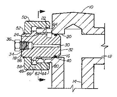
FIGURE 1 is a sectional view of a portion of the body
of a choke adapted to use a flow bean ~or its flow restric-
tion and illustrating the improved connection oP a blanking
plug into the choke body.
FIGURE 2 is a view of the blanXing plug shown in
FIGURE 1 with a portion of the plug being shown in section
and the other portion being shown in elevation.
FIGURE 3 is a sectional view taken along line 3 - 3 in
FIGURE 1 to show the relative position of the choke body
and the blanking plug which form the improved connection of
the present invention.
FIGURE 4 is a sectional view similar to FIGURE 1 but
with the blanking plug moved to its pressure relieving
position.

o7~5B
FIGURE 5 is a sectional view of a prior art choke
having a flow bean mounted in one of its body passages and
a blanking plug secured in another of its body passages.
Description of the Preferred Embodiment
Choke C of the prior art as illustrated in FIGURE 5
includes the body B having passages Pl, P2 and P3. Flow
bean FB i5 threaded into passage P1 and blanking plug BP is
positioned in passage P2. Tapered seat Sl is provided near
the inner end of passage P2 and blanking plug BP includes
seal S on its tapered inner shoulder S2 which sealingly
engages tapered seat Sl. Threaded securing ring or nut N
engages external threads T on the exterior of body B sur-
rounding passage P2 to retain blanking plug BP within
passage P2. Nut N is held in position around blanking plug
BP between snap ring SR and oute.r flange OF on blanking
plug BP. If nut N is unthreaded while there is pressure
within choke body B, the pressure may forcibly eject
blanking plug BP out of passage P2. Nut N includes the
provision of an opening or port O through which some
bleeding of the pressure may occur during the unthreading
after seal S disengages from tapered seat S1.
In the improved structure of the present invention,
choke body 10 is partially shown in Figures 1 and 4 and
includes internal passages 12, 14 and 16 which all inter
sect within body 10 as shown~ Passage 16 is closed by
blanking plug 18 which is used for this function in those
chokes in which the flow restriction is provided by a flow
bean (not shown) or other restriction mounted in one of the
other passages 12 or 14. In the event that a variable
choke is to be provided then a bonnet (not shown) which
would carry the movable plug or needle which coacts with a
seat to restrict flow through the passages is secured to
body 10 and extends into passage 16 in the same manner as
blanking plug 18. In such structure the bonnet would be
constructed similarly to blanking plug 18 to embody the

- 5 - ~ 3
improved connection of the present invention for its
connection into the choke body 10.
Passage 16 includes annular sealing surface 20 extend-
ing from the intersection of passage 16 with passage 14 and
annular recess 22 extending from the outer end of surface
20 to inwardly directed lip 24. Three slots 26 are pro-
vided in lip 24 as best seen in FIGURE 3 for the purpose
hereinafter explained.
Blanking plug 18 includes body 28 having bore 30
extending therethrough from its inner end 32 and ending in
counterbore 34 which is threaded to receive threaded
sealing plug 36. Groove 38 extends around the exterior of
body 28 near its inner end 32 and receives seal ring 40
which seals against sealing surface 20 when plug is in its
sealing position as shown in FIGURE 1. A plurality of pins
42 are secured to body 28 in a position spaced around body
28 as can be seen in FIGURES 2 and 3. Orienting pin 44 is
secure in body 28 at a position to engage within orienting
slot 46 as shown in FIGURE 3. Flange 48 extends outwardly
from plug body 28 at a position slightly outward or away
- from inner end 32. Securing ring 50 is supported around
the exterior of plug body 28 between the outer side of
flange 48 and the inner side of split ring 52 which is
positioned in groove 54 around body 28 near outer end 56 of
body 28. Securing ring 50 includes inwardly extending
flange 58 which is secured between flange 48 and 5plit ring
52 and inner threads 60 engage and coact with external
threads 62 on body 10 surrounding the outer end of passage
16.
Blanking plug 18 is initially provided with securing
ring 50 and when it is secured in place by split ring 52,
plug 18 is inserted into passage 16 with pins 42 positioned
to pass through slots 26 and thereafter plug 28 is rotated
to position orienting pin 44 for entry into orienting slot
46 in lip 24. This rotation moves pins 42 out of alignment
with slots 26. With plug 18 position as described, secur-
ing ring 50 is threaded inward to mo~e pins 42 against

7~
shoulder 64 at the inner end o~ recess 22 and flange 48
against the exterior of body 10 surrounding the outer end
of passage 16.
With the improved present invention installed as shown
it will hold pressure within choke body 10 and in the event
it is to be removed it can be released by unthreading
securing ring 50 until seal ring 40 is within recess 22 and
no longer in sealing engagement with sealing surface 20.
This is the position illustrated in FIGURE 4 and in this
position of blanking plug 18, pressure is vented from the
interior of choke body 10 without any danger that plug 18
will be ejected by the pressure contained in choke body 10~
The pressure fluid is exhausted from the interior of
securing ring 50 through port 66 which extends through
securing ring 50. When the pressure fluid has ~een com-
pletely exhausted, securing ring 50 can be further un-
threaded to allow plug 18 to be completely withdrawn from
the interior of passage 16.

Representative Drawing
A single figure which represents the drawing illustrating the invention.
Administrative Status

2024-08-01:As part of the Next Generation Patents (NGP) transition, the Canadian Patents Database (CPD) now contains a more detailed Event History, which replicates the Event Log of our new back-office solution.

Please note that "Inactive:" events refers to events no longer in use in our new back-office solution.

For a clearer understanding of the status of the application/patent presented on this page, the site Disclaimer , as well as the definitions for Patent , Event History , Maintenance Fee  and Payment History  should be consulted.

Event History

Description Date
Inactive: IPC from MCD 2006-03-11
Inactive: Abandon-RFE+Late fee unpaid-Correspondence sent 1997-01-06
Inactive: Adhoc Request Documented 1997-01-06
Application Not Reinstated by Deadline 1996-07-06
Time Limit for Reversal Expired 1996-07-06
Inactive: Adhoc Request Documented 1996-01-04
Deemed Abandoned - Failure to Respond to Maintenance Fee Notice 1996-01-04
Application Published (Open to Public Inspection) 1990-07-25

Abandonment History

Abandonment Date Reason Reinstatement Date
1996-01-04
Owners on Record

Note: Records showing the ownership history in alphabetical order.

Current Owners on Record
COOPER CAMERON CORPORATION
Past Owners on Record
KENNARD W. TAYLOR
Past Owners that do not appear in the "Owners on Record" listing will appear in other documentation within the application.
Documents

To view selected files, please enter reCAPTCHA code :


To view images, click a link in the Document Description column (Temporarily unavailable). To download the documents, select one or more checkboxes in the first column and then click the "Download Selected in PDF format (Zip Archive)" or the "Download Selected as Single PDF" button.

List of published and non-published patent-specific documents on the CPD .

If you have any difficulty accessing content, you can call the Client Service Centre at 1-866-997-1936 or send them an e-mail at CIPO Client Service Centre.

({010=All Documents, 020=As Filed, 030=As Open to Public Inspection, 040=At Issuance, 050=Examination, 060=Incoming Correspondence, 070=Miscellaneous, 080=Outgoing Correspondence, 090=Payment})


Document
Description 
Date
(yyyy-mm-dd) 
Number of pages   Size of Image (KB) 
Abstract 1990-07-24 1 26
Claims 1990-07-24 3 127
Drawings 1990-07-24 3 86
Descriptions 1990-07-24 6 252
Representative drawing 1999-07-27 1 18
Fees 1993-12-29 1 58
Fees 1994-12-21 1 75
Fees 1992-12-21 1 61
Fees 1992-01-02 1 64