Language selection

Search

Patent 2007471 Summary

Third-party information liability

Some of the information on this Web page has been provided by external sources. The Government of Canada is not responsible for the accuracy, reliability or currency of the information supplied by external sources. Users wishing to rely upon this information should consult directly with the source of the information. Content provided by external sources is not subject to official languages, privacy and accessibility requirements.

Claims and Abstract availability

Any discrepancies in the text and image of the Claims and Abstract are due to differing posting times. Text of the Claims and Abstract are posted:

  • At the time the application is open to public inspection;
  • At the time of issue of the patent (grant).
(12) Patent: (11) CA 2007471
(54) English Title: TAPER-LOC DRAG LINK AND PIN
(54) French Title: GOUPILLE ET ACCOUPLEMENT A BLOCAGE CONIQUE
Status: Expired and beyond the Period of Reversal
Bibliographic Data
(51) International Patent Classification (IPC):
  • B65G 19/22 (2006.01)
  • F16G 13/07 (2006.01)
(72) Inventors :
  • BARTOLETTO, AVELLINO GUISEPPE (United States of America)
(73) Owners :
  • AVELLINO GUISEPPE BARTOLETTO
(71) Applicants :
(74) Agent: GOWLING WLG (CANADA) LLP
(74) Associate agent:
(45) Issued: 1994-07-26
(22) Filed Date: 1990-01-10
(41) Open to Public Inspection: 1990-08-10
Examination requested: 1992-12-01
Availability of licence: N/A
Dedicated to the Public: N/A
(25) Language of filing: English

Patent Cooperation Treaty (PCT): No

(30) Application Priority Data:
Application No. Country/Territory Date
308,462 (United States of America) 1989-02-10

Abstracts

English Abstract


ABSTRACT
Drag chain link and pin construction providing press fit nonrotational
seating of pin ends in bifurcated boss ended arms of each link thereby
excluding introduction of abrasive, wear producing particles, particularly
encountered in cement manufacturing kilns.


Claims

Note: Claims are shown in the official language in which they were submitted.

CLAIMS
1. Drag chain link and pin assembly comprising bifurcated link with
integral arms extending from apertured barrel, said arms having end bosses
spanning the barrel of an adjacent link with barrel-aligned connecting pin
apertures characterized by connecting pin means positively secured against
rotation in said bosses, and tight fit arm boss and connecting pin means for
excluding entrance of abrasive material.
2. Combination of claim 1 wherein said first means includes
interengaging flat surface boss and connecting pin means.
3. Combination of claim 1 wherein said second means includes
interengaging tapered surface boss and connecting pin means.
4. Combination of claim 1 wherein said second means comprises a tight
fit shoulder engagement between said connecting pin and boss at one end, and a
tight tapered surface engagement between said boss and said connecting pin at
the other end.
5. Combination of claim 4 including a press fit locking pin extending
through said tapered end.
6. Combination of claim 4 including an enlarged head adjacent said
shoulder.

Description

Note: Descriptions are shown in the official language in which they were submitted.


~C~07~
TAPER-I~C DRAG LINK AND PIN
BA~G~ND OF 1~3E INV~TI~N
Drag chains employed in the cement industry encounter a hostile abrasive
environment tending to produce rapid wear. Cement is primarily made of
limestone, ~nd hard igneous rock materials in rotary kilns. Kilns are fired at
one end heating the materials which mixe~ under the rotary action of the kiln,
progresses through four chemical reactions at high temperatures ,~nd emerges ~s
cement clinker at the output en~ After this, the clinker is cool~d and moved
to the ~all mills. A sequence of drag links joined to each other by pins
comprise the endless drag chain whi~h is driven by a sprocket and conveys the
abrasive material along the bottom of a trough to the ball mills for final
gri,nding.
Each link of the drag chain has a barrel at one end with side arms
extending lengthwise and outward sufficient to reach the barrel of the next
link. A pintle pin crosses through a hole in the barrel of one link and boss
holes in the extremities of the two side arms of the next link to connect the
successive identical cast drag links and form the endless drag chain.
Conventional pintle pins are normally constructed of uniform diameter steel rod
headed at one end with a headed locking pin inserted in a crosshole at the
other end and retained by a cotter pin. The rods normally have loose fits in
all of the link holes through which they pass and are particularly vulnerable
to the introduction of abrasive ~rit near the ends of the pins in the holes in
the exposed bo~ses on the extremities of the arms of the drag links. Excessive
wear occurs there ,~etween the ends of the pins and the side arm boss holes of
the links engag~d by such ends.

:` ~ 2~ 4~
.
..
BRIEF DESCRIPrI(:~N OF TEIE TAPE:~LOC PIN INV~ION
The ends of the T~PER-LOC PINS are adapted for press fit respectively in
` each of the side arm bosses of the drag link engaging such ends. The usual
pivotal clearance fit is confined to the center barrel element of the link.
The TAPER-LOC PIN is provided with a head seated in a counterbore in one of the
link side arm bosses; a reduced shoulder for a tight fit in the bore extending
through said side arm boss; a further reduced shaft passing through the barrel
with a pivotal fit; a further reduced tapered end having a flat face driven
into the other side arm boss with a tight fit in a matching tapered boss hole
having a matching flat to positively prevent the TAPER-LOC PIN from rotating;
and a cross locking pin press fitted into a hole through the tapered pin near
that end as a redundant safety feature to positively prevent link pin
extraction under any condition.
The tight fit at b~th ends of the TAPER-LOC PIN and the side arm holes
which engage them prevent abrasive grit from entering and the matching flats
prevent rotation between the TAPER-LOC PIN and the boss holes in the drag link
l arms both of which greatly reduce wear which is the objective of the inventio~
_ _ .. . . . ...... . .
BRIEF DESCRIPTICN OF T9E DRAWINGS
Fig. 1 is a fragmentary partially sectioned view of a prior art chain link
and pivotal pin connection;
, Fig. 2 is a view of the connecting and retaining pins per se shown
, assembled in Fig. l;
.j 2
i

r ~ 2al~7~7~L
Fig. 3 is an end view of the pin connection shown in Fig. l;
; Fig. 4 is a partially sectioned plan view of of a drag chain link and pin
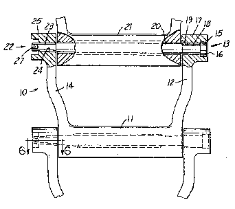
assembly illustrating the TAPER-LOC D~G LINK AND PIN construction of the
present invention;
Fig. 5 is an end view of the chain link illustrated in Fig. 4;
Fig. 6 is a fragmentary sectional detail view of the TAPER-L0C PIN end per
se of the present invention;
Fig. 7 is a view of the link pin and locking pin per se shown assembled in
, Fig. 4;
Fig. 8 is a perspective view of the TAPER-LOC ~RAG LINK AND PIN assembly
of the present invention partially sectioned to illustrate the interlocking
construction;
., ,
DETAILED DESCR~PTICN OF PREFERRED EMBODIMENTS -
; With reference to Fig. 4, bifurcated drag chain link 10 comprises central
~, barrel 11, having integral side arm 12 ~or receiving the headed end of link
1 pivot pin 13, and side arm 14 for receiving the other en~ Pin 13 is provided
`! with head 15 fitting within counterbore 16 in boss 17 at the end of side arm
, ,,
12. Next to the head, a slightly reduced shoulder 18 on pin 13 provides a
tight fit in boss bore 19 followed by further reduced shaft 20 projecting
through barrel 21 with a pivotal fit. Tapered end 22 of pin 13 with flat 23
engages tapered aperture 24 In boss end 25 of side bar 14~ Referring to Fig.
6, flat 26 of the aperture matches pin flat 23 to positively prevent rotation
when driven in place. Locking pin 27 extends through tapered end 22 (Fig. 4)
with a press fit to c~mplete the assembly.
'~
: t

7~1.
In comparison, with reference to Figs 1-3, conventional link pin 28
comprises simply straight shaft 29 headed at 30 and, at the other end, with
locking pin 31 passing through hole 32 secured by bent end 33. Pin 28 has a
loose fitting clearance with all elements of the link providing access for
abrasive grit leading to relatively rapid wear. In oontrast, the press fit of
the present TAPER-LOC PIN in each of the side arm bosses positively excludes
any entrance of abrasive material at eit:her end of the link pin so that only
the relatively protected and inaccessible clearance between the barrel and
bosses of adjacent links offers any potential opening for intrusion of abrasive
particles.
. . .
.
.j ~ .
:':
~i :
. 4

Representative Drawing
A single figure which represents the drawing illustrating the invention.
Administrative Status

2024-08-01:As part of the Next Generation Patents (NGP) transition, the Canadian Patents Database (CPD) now contains a more detailed Event History, which replicates the Event Log of our new back-office solution.

Please note that "Inactive:" events refers to events no longer in use in our new back-office solution.

For a clearer understanding of the status of the application/patent presented on this page, the site Disclaimer , as well as the definitions for Patent , Event History , Maintenance Fee  and Payment History  should be consulted.

Event History

Description Date
Inactive: IPC from MCD 2006-03-11
Inactive: Adhoc Request Documented 1996-01-10
Time Limit for Reversal Expired 1995-07-10
Letter Sent 1995-01-10
Grant by Issuance 1994-07-26
Request for Examination Requirements Determined Compliant 1992-12-01
All Requirements for Examination Determined Compliant 1992-12-01
Application Published (Open to Public Inspection) 1990-08-10

Abandonment History

There is no abandonment history.

Owners on Record

Note: Records showing the ownership history in alphabetical order.

Current Owners on Record
AVELLINO GUISEPPE BARTOLETTO
Past Owners on Record
None
Past Owners that do not appear in the "Owners on Record" listing will appear in other documentation within the application.
Documents

To view selected files, please enter reCAPTCHA code :


To view images, click a link in the Document Description column (Temporarily unavailable). To download the documents, select one or more checkboxes in the first column and then click the "Download Selected in PDF format (Zip Archive)" or the "Download Selected as Single PDF" button.

List of published and non-published patent-specific documents on the CPD .

If you have any difficulty accessing content, you can call the Client Service Centre at 1-866-997-1936 or send them an e-mail at CIPO Client Service Centre.

({010=All Documents, 020=As Filed, 030=As Open to Public Inspection, 040=At Issuance, 050=Examination, 060=Incoming Correspondence, 070=Miscellaneous, 080=Outgoing Correspondence, 090=Payment})


Document
Description 
Date
(yyyy-mm-dd) 
Number of pages   Size of Image (KB) 
Abstract 1997-09-23 1 26
Drawings 1997-09-23 2 84
Claims 1997-09-23 1 47
Descriptions 1997-09-23 4 200
Representative drawing 1999-08-02 1 11
Fees 1993-12-21 1 31
Fees 1992-11-30 1 34
Fees 1991-12-19 1 27
Courtesy - Office Letter 1990-07-05 1 56
Courtesy - Office Letter 1992-12-21 1 41
PCT Correspondence 1994-04-20 2 51
Prosecution correspondence 1990-07-12 1 23
Prosecution correspondence 1990-09-25 1 27
Prosecution correspondence 1992-11-30 1 28
Prosecution correspondence 1993-01-31 1 24