Note: Descriptions are shown in the official language in which they were submitted.
. PRINI~ING SLE}~VE~ AND NE~}IOD~ ~FOR MOUN~ING
AND DIBMOUN~I!ING ~3UCII PRINTING ~LEEVEB
BAC~ROUND O~ ~r~E I~VBN~ION
This invention relates t:o printing sleeves which
' are readily mountable onto and dismountable from
¦ printing cylinders, and more particularly to printing
sleeves which are expandably mountable and dismountable -
employing a pressurized gas.
In past printing operations, flexible printing
plates were mounted onto the outer surface of a
printing cylinder. These plates were used for printing
of ink images onto a printing medium. Typically, the
back o~ the plates was adhered directly to the printing
cylinder. Since these plates were not readily
interchangable from ona cylinder to another, the use of
a multiplicity of printing cylinders to perform a
multiplicity of jobs was reqllired. This presented
severe storage and cost problems to the end user.
Therefore, in an effort to overcome this problem,
printing sleeves were developed which WerQ mountable
onto and~dismountable from the printing cylinder~.
Compressed gas, generally compressed air, passing in a
substantially radial direckion from holes located
within the printing cylinders, was used to expand the
sleeve to a limited extent for ~acilitating the
mounting and dismounting operations.
~ ' ' .
20~ ~98
The first patent to describe this latter mode o~
mounting and dismounting of a printing sleeve was U.S.
3,146,709. In that patent, a "wound" printing sleeve,
i.e., a helically wound paper sleeve, was fitted onto a
hollow printing sleeve. The printing sleeve was used
as a carrier roll for rubber printing plates attached
thereto. Air pressure was radially applied through the
holes in the external surface of the printing cylinder
for limited expansion of the sleeve. The sleeve was
then axially mounted onto the printing cylinder by
moving the cylinder to an upright position and filling
the internal chamber of the cylinder with compressed
air. As the sleeve was moved over the upper end of the
cylinder, the exiting air expanded the sleeve and a
lubricating air film was in~erposed between the inner
sleeve and the outer cylinder. This air film permitted
the axial movement of the sleeve to a position about
the cylinder. When the sleeve was in such a position,
the air ~'low was terminated, and the sleeve contracted
in place about the cylinder.
However, difficu]ty has been encountered when
wound sleeves are employed since expansion does not
ef~'ectively take place unless high pressure air,
substantially higher than the 50-100 psi air generally
available in production ~'acilities, is radially
conveyed between the sleeve and the printing cylinder
to facilitate the mounting and dismounting operation.
2~7~
This expandability problem occurs because of the
thickness of the sleeve walls and the nature of the
materials of construction. If pressures above the
available air pressure at the production facility are
required to expand the sleeve, auxiliary sources of
compressed air must be purchased. For example, in
printing operations where sleeve thicknesses of about
0.015" or greater are required, such as in the process
printing industry, wound sleeves cannot readily be
employed because they do not undergo the re~uisite
expansion using available production compressed air.
Furthermore, these wound sleeves cannot be effectively
used because of the leakage problems inherent in their
design, which in this case, U.S. 3,146,709, comprises a
polyester film held in position by helically-wound
paper tape. This type of construction forms a leakage
path for the air and reduces-the ef*ectiveness of the
lubricating fluid.
In order to overcome the problems inherent in the
U.S. 3,146,709 wound printing sleeve, U.S. 3,978,254
has provided a mechanically adhred wound printing
sleeve in which three layers o~ adhesive tape are
helically wound about a mandrel to form a carrier
sleeve, with two of the helixes being wound at the same
angle and the remaining helix being wound at a
different angle. The convolution of the helixes are
said ~o impart some degree of strength, rigidity and
- %~7g~8
leakage protection to the printing sleeve. Neither of
the printing sleeves of U.S. 3,146,709 or U.S.
3,978,254 is unitary in const:ruction, but is instead
fabricated of a composite of wound materials.
Furthermore, the outer surface of the U.S. 3,978,254
wound sleeve has a plurality of surface irregularities
formed therein and is therefore not "round" to the
extent required by the flexographic printing industry.
These carrier sleeves are made of a flexible, thin tape
material which provides a minimum of structural
integrity which exhibit minimal strength and durability
properties. Moreover, as the printing plates are
adhered to the printing sleeve they are moved from one
position to another as they are aligned on the plate
sur~ace. In order to trim excess material from the
plate from the sleeve surface, they must be cut with a ~-
sharp instrument such as a knl~e. The synthetic
plastic tape used to form the above-described sleeve
cannot withstand even the minor cutting action required
in positioning of the printing plates.
Another type of printing sleeve is one which is
made of a metallic material. As in the case of wound
sleeves, metallic sleeves are not readily expandable
and therefore must have a wall thickness which is be
quite thin, i.e., thicknesses of up to only about
0.005", in order to be capable of undergoing the
limited expansion required of printing sleeves. ~s
2~7~
indicated above, this minimum thickness level required
of metallic sleeves is a problem in applications such
as process printing and the like. Moreover, printing
metallic sleeves are not durable and are readily
damages. For instance, they can easily form kinks in
their outer surface when they are stored without being
supported by a printing cylinder.
Dimensional stability is a problem in printing
applications requiring that the outer surface of a
printing sleeve structure have a true cylindrical
shape. In some cases, this true cylindrical shape must
even be within a 0.001"-0.0025'l tolerance level in
order to be acceptable in, for example, uses such as in
the process printing industry. The outer printing
surface in these applications must accurately conform
to a uniformly constant, cylindrical outer shape in
order to accurately imprint a print image onto a
printing medium. Many o~ these prior art printing
sleeves do no~ meet these requisite tolerance levels.
U.S. 4,144,812 and U.S. 4,144,813 provide non~
cylindrical printing sleeves and associated air-
assisted printing rolls designed in a tapered or
stepped-transition configuration, the change in the
sleeve or printing cylinder diameter from one end to
the other being progressive, i.e., increasing or
decreasing according to the direction one is moving
along the printing sleeve or roll~ The printing roll
.. . . . . . . .. .. .. .. .
7t)~
comprises an outer surface having one end o~ a diameter
greater than the other longitudinal end~ The printing
sleeve has an inner surface clesigned to form an
interference fit with the outer surface of the printing
roll only at thP designated working position, and not
along the entire axial uniform cross-sectional extent
of the tapered sleeve.
This non-cylindrical sleeve is fabricated of a
highly rigid material having a low degree of
expandability. These sleeves have a thickness of about
0.015". An extremely high air pressure, in excess of
125 psi, and typically about 250 psi or higher, is thus
required to be introduced as the sleeve is being fitted
onto the underlying air-assisted, printing roll in
order to extend the radial dimension of the printing
sleeve to a position capable of achieving complete
coverage of the printing cylinder by the sleeva.
Complete coverage i5 required in thi~ system to achieve
a proper interference fit. Since a pressure in excess
of 125 psi is required herein, the syst~m must satisfy
various governmental regulations relating to pressure-
rated conta:iners. Conventional cylindrically shaped,
air-assisted printing presently on hand cannot readily
be retrofitted to accommodate this non-cylindrical
configuration because they cannot meet the above-
described pressure-rating requirement. There~ore, they
must be replaced, at great cost, by new non-cylindrical
~n~7~
printing cylinders capable of meeting these government
regulations.
U.S. 4,119,032, describes an air-assisted printing
cylinder mounted in a printing machine in such a way
that a printing sleeve on its outer surface can be
removPd axially while the roll remains substantially in
- its working position. One end bearing of the printing
cylinder is removably secured to a side of the machine
frame. For axial positioning, an adjustable restrainer
engages the roll axle at that end. Beyond the other
I side ~rame a counterpoise acts on the printing cylinder
axle to support the printing cylinder when one end
bearing is removed.
Finally, in U.S. 4,089,265, a flexographic
printing roll is provided comprising a rigid base tube
having perforations in the form of a plurality of small
apertures and a printing sleeve on the tube strained to
grip the tube to retain the sleeve securely on the
tube. There is no underlying printing cylinder in the
conventional sense in this system.
Therefore, a need exists for a cylindrically
shaped printing sleeve which is unitary and airtight,
which can be Erictionally mounted onto conventional
cylindrically shaped printing cylinders having a
complementary outside diameter, which is readily
expandable using a low pressure ~luid, and which has a
~ q2r~
., .
wall thickness and a true outer wall surface capable of
being used in process printiny applications.
!
~UM~ARY OF THE INVENTION
This invention relates to a cylindrically-shaped
printing sleeve which meets the aforementioned needs
and overcomes the above-described problems associated
with prior art sleeves, particularly sleeves for the
process printing industry.
First, the printing sleeve of the present
invention comprises a printing sleeve body
cylindrically-shaped having a constant cross-sectional
diameter. This printing sleeve is therefore readily
axially mountable on, and dismountable from, a
complementary cylindrically-~haped printing cylinder
having a constant cross-sectional diameter. In this
way, conventional printing cylinders in use in various
manu~acturing facilities do not have to be replaced at
great cost to the user.
The present invention provides for a printing
sleeve structure having a printing sleeve body which is
unitary and substantially airtight. Thus, this sleeve
is strong, durable, and does not leak, all of which
being problems which exist with re~pect to prior art
wound print:ing sleeves. More specifically, the subject
~leeves preferably have are unitary structures because
they are substantially seamless inner and outer
` 20~7698
. .
:.'
-
cylindrically-shaped wall surfaces, and are airtight
because they are constructed of materials which are
high strength and non-permeable in nature. Strength
and durability are properties clearly lacking in thin-
i 5 walled (0.005") metallic sleeves~ The preferred
printing sleeves of this invention have a wall
thickness of at least about 0.015".
Mounting of the printing sleeves of the present
i invention onto a conventional printing cylinder can be
readily accomplished by expanding the diameter of these
sleeves by the introducion of a relatively low fluid
pressure between the inner wall surface o~ the sleeve
and the outer wall surface of the printing cylinder.
Prei~erably, in the printing sleeves of this invention,
each of the inner and outer wall surifaces of the
printing sleeve body has a substantially constant
radial diameter. The printing sleeve is contractable
by removing the expanding forces.
Typically, th~ expanding forces are applied using
a low pressure fluid, such as low pressure air and the ;
like. The low pressure fluid is typically introduced
at a pressure, at ambient temperature, of not more than
about 100 psi, preferably not more than about 80 psi,
and more pre~erably not more than about 50 psi, whereby
the cross-sectional diameter of the printing sleeve is
expanded for mounting of the printing sleeve onto the
printing cyLinder. The ability to use lower pressure
7~
gas is important since most production facilities do
not have, for example, high pressure yas available for
conducting the mounting and dismounting operations.
Moreover, since this pressure is below 125 psi, there
is no problems with ~overnment regulation as a
pressure-rated container.
The printing sleeve exhibits certain preferred
physical properties. These include a printing sleeve
flexural modulus of at least about 6 x 10⁵ lbslin2, and
more preferably at least about 10 x 105 lbs/in2. This
provides excellent structural integrity but at the same
time the low flexural modulus value permits the
required level of expandability with the above
described introduction of a relatively low pressure
fluid. For purposes of this invention, flexural
modulus was determined using ASTM D2412.
The printing sleeve of the present invention can
also be fabricated with a wall thickness substantially
greater than conventional metal printing sleeves.
Preferably, this wall thickness is at least about
0.015", more preferably at least about 0.020 ", and
most preferably at least about 0.040". In this way,
printing plates having a much higher range of
thicknesses can be employed. Although sleeves having a
larger wall thickness can be fabricated by the
teachings of this invention, a practical upper limit
may be a wall thickness of about 0.120".
~:~i7~
By employing the subject printing sleeve, a
stiffness factor, can be attained of at least about
7.26 x 105 inch-pounds. This clearly describes a
printing sleeve construction having a high level of
strength and expandability. The stiffness factor was
determined using ASTM D2412(10.2).
The printing sleeve.s of this invention is
typically fabricated of a non-metallic material,
preferably a polymeric material. The printing sleeves
preferably comprise a reinforced non-permeable laminate
structure including at least one reinforcing internal
layer of a woven fabric of synthetic fibers or organic
fibers, for particularly providing high tensile
strength. A second internal layer may also be included
which comprises at least one non-permeable internal
layer, typically synthetic fibers. Preferably, the
synthetic and organic fibers are of high strength, and
the reinforced non-permeabl~ internal layers comprise a
non~woven fahric of synthetic fibers.
The outer wall surface of the printing sleeve
exhibits a limited dimensional tolerance whereby
printing plates can be mounted ~or complementary
frictional engagement onto the outer wall surface of
the printing sleeve so that the printing elements of
differing colors located on the printing plate surface
register within the exact specifications required for
conducting process printing operations. Prefexably,
2 ~3 ~rl~ ~ 9 8
:`
12
the printing sleeve exhibits a maximum difference in
the trueness of its outer wall surface, when the sleeve
is mounted on a true cylinder, is not more than about
0.005", preferably not more than about 0.0025", and
most prsferably not more than about 0.001".
This invention also contemplates a method for
axially mounting the previously described non-metallic,
airtight, unitary, cylindrically-shaped printing sleeve
of constant cross-section configuration, which includes
substantially saamless inner and outer cylindrically-
shaped wall surfaces of constant cross-sectional
diameter, onto a complementary cylindrically-shaped,
printing cylinder and for dismounting the printing -~
sleeve therefrom. This is accomplished by expanding
the printing sleeve to a cross-sectional diameter
slightly greater than the diameter of the printing
cylinder. This can be readily accomplished because o~
the above-described physical proper,ties of the sleeve.
The expanded printing sleeve is then axially moved to a
position onto the printing cylinder. Then, the
expanded printing sleeve is contracted to ~orm a
minimum interference fit between the printing cylinder
and the printing sleeve, respectively, and thereby
mounting the printing cylinder onto the printing
sleeve. For dismounting purposes, the sleeve is
expanded, as provided above, and then axially removed
from its position about the printing cylinder.
-l 13
: The foregoing and other objects, features and
advantages of the invention will become more readily
apparent from the following detailed description of a
preferred embodiment which proceeds with reference to
the drawingsO
BRIB~ DE8CRIPTION OF TH~ DRAWINGS
FIG. 1 is a sectional view of an enlarged,
cylindrically-shaped printing sleeve of the present
invention as mounted on a printing cylinder.
FIG. 2 is a perspective view of the cylindrically-
shaped printing sleeve of FIG. 1.
FIG. 3 is an enlarged sectional view taken along
, 2-2 of FIG. 2.
~'. 15
DE~AILBD DE5CRIPTION OF THB PREFERRED EMiBODIMENT
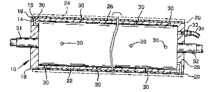
Referring now to ~IGS. 1 and 2, a cylindrically-
`, shaped printing sleeve 10 is provided which comprises
cylindrically-shaped inner and outer walls 14 and 15
which define a hollow inner chamber 16, and a pair o~
end sections 13 and 20. Sleeve 10 is depicted mounted
on an illustrative conventional printing cylinder 22,
such as described in FIG. 3 of U.S. 3,146,709.
Typically, sleeve 10 will serve as a support for
the application of printing plates 24, preferably
~lexographic printing plates (see FIG. 3 in phantom),
which are generally made of of a flexible polymeric
~30~6~3
14
material. Any suitable indicia for printing onto a
printing medium may be set on these printing plates.
Alternatively, outer wall 15 may itself be employed as
the means for printing onto a printing medium. Various
methods can be employed to engrave the outer wall 15.
For example, one could employ chemical or photochemical
engraving techniques to form the requisite means for
` printing the print indicia.
The printing sleeve 10 and the printing cylinder
22 are cylindrical and have a constant diameter. The
outer wall 23 of the cylinder 22 has a slightly larger
diameter than the inner wall 14 so that the sleeve will
firmly frictionally fit onto the cylinder. The
cylinder 22 is hollow and has a cylindrical chamber 25
` 15 which is used as a compressed air chamber. The
cylinder 22 comprises a cylindrical tube 26 fitted with
airtight endplates 28 and 29. A plurality of spaced-
apart, radially-extending apertures 30 are provided in
the tube 26 through which air from the chamber 25 may
pass for expanding the sleeve 10 during mounting and
diæmounting operations. Air is introduced into the
chamber 25 through air hose 32. Trunnions 31 and 32
are provided for rotationly supporting cylinder 22. A
coupling element 33 is disposed within endplate 29 and
provides a means for connecting air hose 32 to cylinder
22 for introducing compressed air to the cylinder
chamber 25.
:'. -,'.
6~
The cylindrically-shaped printed sleeve 10
typically comprises a reinforced, non-permeable
laminate structure. An example of a typical formation
process for producing such a reinforced non-permeable
laminate printing sleeve is as follows: A typical
internal steel mandrel of about 5.5 feet in length and
about 1.5-15 inches in diameter is employed as the
structural form in the fabrication of the reinforced
non-permeable laminate printing sleevs 10. The mandrel
is a cylindrically-shaped printing cylinder having a
hollow internal chamber and a substantially
cylindrically-shaped outer wall surface including an
array of holes located in the cylinder wall. The
pressurized air employed to expand a printing sleeve
passes from the internal chamber outwardly through the
array of air holes. In the printing sleeve formation
process these air holes are first taped shut in order
to prevent the synthetic resin employed in forming the ~
printing sleeve from passing through the air holes into ::
the central chamber of the mandrel. The diameter of
the outer wall section o~ the printing cylinder is
sized to produce a printing sleeve having an inner wall
surface of substantially constant diameter, the
magnitude of such inner wall being slightly smaller
than the diameter o~ the outer wall section of the
printing cylinder on which it will ultimately be
7~
16
mounted to promote an interference fit of the sleeve
about the ultimate printing cylinder.
The printing sleeve formation process can be
initiated by applying a mold-release agent such as
polyvinyl alcohol and the like, onto the outer wall
section of the mandrel. The use of this agent allows
the sleeve to be readily removed from its position
about the mandrel after the formation process has been
completed. Next, a synthetic resin capable of being
formed into a unitary, airtight printing sleeve body
having the physical properties previously described is
applied to the outer wall section of the mandrel. For
example, Derakane~, a vinyl ester resin manufactured by
the Dow Chemical Company, can be employed for this
purpose. The catalyst used in curing the resin is a ;~
methyl ethyl ketone peroxide material, such as Hi Point
90 manufactured by Witco Chemical Corporation. The
resin, when cured, has a high degree of toughness,
chemical resistance, impact resistance and a high level
of tensile strength.
An internal reinforcing layer of high strength
synthetic or organic fibers can then be applied about
the resin material. Typically, at least one
reinforcing composition layer is employed for this
purpose because o~ its generally high strength and
.. ..
lightweight properties. In the preferred case, as
shown in FIG. 3 a single layer 17 of a woven composite
" . ~'
6~3
17
. .
of synthetic fibers, such as aramid fibers manufactured
by DuPont under the registered trademark Kevlar~, is
used herein. Kevlar~ is ava:ilable in a number of
fabric weaves. In this case, a single layer of 1.8 oz
per square yard Kevlar~ a,ramid fibers was employed as
the reinforcing composite material. Alternatively,
woven fiberglass filaments in the ~orm o~ a composite
boat cloth fabric can be employed as the internal
reinforcing layer. For instance, a boat cloth
composite fabric manufactured by Owens Corning can be
used herein.
At least one layer of an non-permeable material,
such as a non-woven, non-apertured synthetic material,
is then preferably wrapped about the internal
reinforcing layer. in this case, as depicted in FIG.
3, four layers of the non-woven, non-apertured material
13 were applied. A polyester non-woven polymeri~ web,
such as Nexus'~, manufactured by Burlington Industries,
is useful for this purpose. This material provides the
overall printing sleeve structure with machinability,
shock resistance, and, when saturated with resin,
provides a ~luid-tight, and particularly an airtight,
barrier. The remaining portion of the resinous
material was then applied thereto.
Next, the completed structure was allowed to cure
for a period of time so that the resin would become
cured and crosslinked and dimensionally stable. This
~(37~&
18
was accomplished under exothermic conditions for a
period of time of about two hours. The formation
mandril was continually rotated during the exothermic
period. The printing sleeve was then removed from the
mandril and post-cursd for a period of time and at an
elevated temperature. Here, the post-cure was
conducted for a period of 30 minutes at a temperature
of 170F, in a post-cure oven. The printing sleave was
then removed from the oven and allowed to cool to
ambient temperature.
At that time, the interference fit was checked to ~-
determine whether it was within acceptable parameters.
Preferably, the interference fit of the sleeve about
the printing cylinder is from about 0.007" up to about
0.015", and more preferably from about 0.009" up to
ahout 0.013". The printing sleeve was then machined to
the requisite outer cylindrically-shapQd wall section
dimension, employing a lathe.
The dimensional tolerance of the printing sleeve
was detexmined by using a dial indicator to measure the -
overall axial variation in the diameter of the entire
surface of the outer wall section o~ the printing
sleeve. For flexographic printing use, the limited
dimensional tolerance of the printing sleeve should be
not more than about 0.001. This type of printing is
known as process printing. The printing sleeve
produced herein met the criteria for process printing
7~;~8
19
use. However, for other uses such as line printing,
which includes bread bag printing and the like, a
limited dimensional tolerance of not more than 0.0025
is acceptable. Finally, in newsprint applications or
the like where fine printing i5 not a critical
parameter, limited dimensional tolerances of not more
than about 0.005" can be employed.
Having illustrated and described the principles of
my invention in a preferred embodim~nt thereof, it
should be readily apparent to those skilled in the art
that the invention can be modified in arrangement and
detail without departing from such principles. We
claim all modifications coming within the spirit and
scope of the accompanying claims.