Note: Descriptions are shown in the official language in which they were submitted.
~-~ 32405CA
~LKYLATION CATALYST ISOLATION
This invention rela-tss generally to method and apparatus for
handling fluids. In one aspect i-t relates -to apparatus for fluid
handllng in an alkylation process. In another aspect it rela-tes to a ..
method for reducing spillage of acidic materifl1 in the event of a leak
in an alkylation process.
~ack~_ound of he Inven_:Lon
It 1.s common practice in the petroleum ind~lstry -to produce
high octane motor fuel by fllkylnt.ing an iæopara:Efi.n with an olefin :In
the presence of a cfltalyst which preferably is l:lquid hydrofluoric acid
: or hydrogen fluoride (~IF). Such a process is commonly known as an HF
alkylation process or merely an alkylation process. The effluent from
the alkylation reactor containing hydrocarbon and acid, is usually
passed -to a generally vertical arranged settler vessel at an
intermedlate point along the leng-th of the settler vessel. A
hydrocarbon phase is separated from an acid phase in the settler vessel,
:. wtth the hydrocarbon phase contained in the upper portion of the settler
vessel and the acid ph~se contained in a lower portion of -the settler
., vessol. Accord:Lngly, fl ~Lquid-liquLd :interface between the acid phase
and hydrocart)on phase :ls formed within the sett:l.er vesse:L. As used
. hercin, the liqui.d-llquid lnterface ls located flt a po:lnt along the
: heigbt of -the set-tler vessel where the flcid concentration of the
l material in the settle:r vessel is greater by a predetermined amount than
the acid concentration in the alkylate product supplied to -the settler
~; from the reactor. The hydrocarbon phase is fractionated to separate low
.
.
;~ 9~t7
r ~ 32~05CA
boiling hydrocflrbons ~from the alkylate product while the acid phase is
; cooled and recycled to the alkylation reactor for reuse in the
alkylation process. As necessary, acid catalyst can be withdrawn from
the system for purification. The purified acid catalyst and, as
necessary, additional fresh acid is re-turned to the alkylation reactor.
It is known to improve the economics of an alkylation process
by employing two or more alkylation reactors and passing the individual
alkylflte product streams to a common set-tler vessel, -thereby forming a
common pool of acid catalyst in the lower por-tion of the common settler
vessel. Acid catalyst is then withdrawn from the common pool and passed
in individual s-treams to the respective alkyla-tion reactors. While an
alkylation sys-tem employing multiple reactors and a common acid catalyst
pool is effective for reducing equipment cost while main-taining a
desired hydrocarbon/catalyst ratio for each reactor, and is also
effective Eor increasing production of high quality gasoline boiling ;
range materials, the system presen-ts certain safety considera-tions. For
example, wLth a common acid cataly.st pool, a leak ln one. reactor could
result In spillflge of the entire catalyst pool which supplLes the
multiple reactors.
~ cid catnlyst fluld handlin~ systems assoclated with
alkylation processes are designed w-Lth due concern Eor providing a
non-leaking catalyst fluid handling sys-tem. In order to provide greater
safety, however, it is desirabl0 to reduce, as much as possible, the
spillage that would occur in -the event of a leak affecting the li~uid
acid catalyst.
Accordingly, it is an object of this invention to improve
safety in operating an alkylation process. ~`
A ~Eurther ohlect of this invention is to increase the safety
of a pe-troleum r~E:Lning process and the appara-tus employed thsrein.
~ nother obJect of this tnvention is to provide npparatus and
method for reducing the spillage of acid catalyst in the invent of a
leak in the acid catalyst handling system associated with an alkylation
process.
Summarv o~ the lnvention
,.`~ ' .
. ' , .
... . .
~ . ,.
iJ~ 7
32405CA
` 3
In flccordnnce with one aspect of this lnvention, multiple
chambers are provided in the bot-tom of a common acLd settler vessel to
con-tain the acid catalyst. The number of chambers provided a-t least
corresponds -to -the number of respective reactors which supply alkylate
product to the common settler vessel. Sepflrate acid re-turn streams for
each reactor are also provided so that a leak in one reactor, or i-ts
associated acid cooler, would result in liqnid spillage of no more than
the amount oE the acid catalyst in the chamber of the common settler
vessel associated with that reactor.
In accordance with another aspec-t of -this invention the common
settler vessel is opera-ted with bo-th liquid and gaseous hydrocarbon
phasas at lower pressures, so tha-t -the leak rate resulting from a leak
in a reactor would be minimized.
In a preferred embodiment of this inven-tion a common se-ttler
vessel is provLded wi-th at ieast one baEfle extending from wall to wall
at the bot-tom of the common settler vessel arld upwardly Lnto close
prox:Lmlty, or abt-v~, the interEflce betwe~n the lLquLd ~cLd catfllyst
phase and thc lLquid hydrocarbon ph~se In the common settler vessel.
The bflefle sepflrates the lower portLon of the settler ve~sel Into two or
more chnmbers flnd prevents lLq~lid communLcat:Lon between the quan-tities
of liquid acid ca-talyst which are contained within -the chambers and are
to be recycled to the respective reac-tors. ~ separato outlet is
provided for each chamber in the bottom Oe the common settler vessel for
re-turn of the acid catalyst to the respective reactor and associated
cooler.
Should the acid cfltfllyst level lower :Ln one chamber due to
leakage or spillage, liquid hydrocarbon Erom the correspondingly lowered
: hydrocarbon pha~ thereabove displaces the acid catalyst volume lost and
thus provide6 a llquid seal for the acid catfllys-t in the non-]eaking
chambers. Also fino-ther material which is less dense flnd of hLgher
boiling point than the acid catalyst, could be injected to replace the
spilled acid catalyst and provide the liquid seal.
In fl preferred embodiment of the present invention, four
reactors, each having an associated cooler, are utili~ed. Two riser
reactors are positioned on -two opposite sides of a vertically oriented
.,.. . , . - . ~ :
.:; . : , . . .
,. - . :
32405CA
' 4
settler vessel. Alkylate product streams of the two reactors on one
slde of tlle settler are combined at or above the e,levation of the
settler inlet, and enter the settler in a combined stream. In a similar
manner the alkylate product of the two reactors on th~ other side of -the
se-ttler vessel are combined and en-ter the settler vessel in a single
s-tream. Four separate streams are provided for returning the acid
catalyst from the se-ttler -to four corresponding riser reac-tors via four
corresponding acid catalyst coolers.
Additional. objec-ts and advantages of the invention will be
apparent from the following detailed description of the preferred
embodiment of the invention as illustrated by the drawings in which: ' '
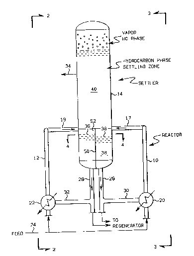
FIG. 1 is a diagrammatic elevation of riser reactors, a
settler vessel and coolers provided in an arrangement suitable for
carrying out the invention. :,.'
FIG. 2 is a side elevation -taken along line 2-2 of FIG. 1. ~'
FIG. 3 is a side elevation taken a].ong lines 3-3 of FIG. 1.
FIG. 4 is a cross secttonal view taken along li.ne 4-4 of ~
FIG. .l. ,
Deta:Lled _escr.Lpt.tol_of the _r ferred Emb_d_ ent
In the following discussion, parts which appcar i.n more than
one of the drawing figures shall be referred to by the same re:Eerence
numeral in each of the drawing figures i.n which -the part appears.
Referring now to the drawings and in particular to FIGS. 1, 2 and 3,
four upwardly extend:ing tubular renctors, referred to hereinafter as
riser reactors, are designated by the reference characters tO, 11, 12
and 13 and are in open communication at the tops thereof with a
generally vertically di.sposed settler vessel 14 via conduits 16, 17, 18
and 19. The settler vessel 14 defin~s a vertically extending separation
æone therew:~thin hflv:i.ng a lower por-tion, an upper port:Lon and fln
intermediate port:Lon. The settler vessel 14 provides means for , .
separating a mixture containing a heavier liquid and a lighter liquid.
~ffluent alkylate, -together with acid ca-talyst, is introduced into a ',-
lower portion of the settler 14 from the outlets of reactors 10, 11, 12
and 13 through condllits 16, 17, 18 and 19. Although four reactors are
37
32405CA
illustra-ted in FIGS. 1~4, any number oE reactors can be used in -the
prac-tice of the invention.
The lower ends of riser reflctors 10, 11, 12 and 13 are in open
fluid communication with coolers 20, 21, 22 flnd 23, respectively.
~Iydrocarbon feed i9 provided via conduit 24 to coolers 20, 21, 22 and 23
along with additional fresh acid where cooled recycled or rerun acid
catalyst is picked up to form a hydrocarbon and acid catalyst mixture.
The hydrocarbon and acid catalyst mixture is dispersed upwardly wi-th
high velocity through the coolers 20, 21, 22 and 23 and into the
corresponding inlets of riser reactors 10, Il, 12 and 13, respectively.
At the bottom of common set-tler vessel 14, ou-tlet conduits 26,
27, 28 and 29, which extend downwardly from settler vessel 14, flre
provided for the withdrawal of liquid acid catalyst for recycle.
Conduits 26, 27, 28 and 29 are connected at the lower ends thereof with
coolers 20, 21, 22 and 23, respectively via corresponding concluits 30,
31, 32 and 33. At an intermediate point along the length of the settler
vesscl 14 an outlet conduit 3~ is provlded for the removal of the
separnted liquicl hydrocarbon product.
In operatlon, a llquld hydrocarbon Eeed mlxture comprlsing a
mixture of an alkyLatlng agent, such as a low boillng olef:ln, e.g.
butylene, and an alkylatable hydrocarbon, sllch as a low boiling
isoparaffin, e.g. isobutane, is introduced through conduit 24, as well
as fresh makeup acid catalyst. The feed mixture is dispersed at high
velocity in the shells of coolers 20, 21, 22 and 23 which contain cooled
liquid acid catalyst, -thus inducing acid ca-talyst circulation into the
hydrocarbon feed mixture by densi-ty difference between the settled acid
38 from the se-ttler 1~ and the fresh makeup acid catalyst dispersed with
the hydrocarbon feed. In this manner acid catalys-t is pLcked up by the
flow act:lon of the llquld hydrocarbon feed mixture. Tlydrocarbon feed
m:lxture flnd cooled recycled acid catnlyst pass through the reactors 10,
11, 12 and 13 in co-curront flow which results in formation of hlgher
molecular weight hydrocarbon material or alkylate of increased oc-tane
valuc, as is well known in the art.
Reaction effluen-t, containing alkylate (i.e. hydrocarbon
product), catalyst and unreacted feed hydrocarbon, passes from reactors
,~ 32405CA
10, 11, 12 and 13 and enters settler vessel 14 through conduit 16, 17 18
and 19. Within settler vessel 14, the effluent from reac-tors lO, 11, 12
and 13 separates into a lower liquid acid phase and an upper liquld
hydrocarbon phase. In accordance with -the inveIltion, however, settler
vessel 14 is preferably operated with both liqu:Ld and gaseous :~
hydrocarbon phases, as illustrated in FIG. 1. ~,,:.,
A liquid-liquid interface is formed at fl point 36 in se-ttler
vessel ],4. The interface occurs at the level betwaen -the lower haavy
acid phase 38 and the lighter hydrocarbon phasc 40. As used herein the
interEace 36 is considered to be the point along -the ver-tical length of "-~;-.<,
the chamber of the common settler vessel 14 where the acid concentration
of the material set-tled in the lower portion of settler vessel 14 is ',
equal to, or greater by a prede-termined amount, than the acid ~
concentration in the reactor affluent material supplied to the common ..
set-tler vessel t4, through conduits 17 and 19. :~:
As most clearly illus-tra-ted in FIG. 4, the lower portion of - '
common settler vassel 14 is provided wlth ba:E:Eles S0 and 52 which divide .,~
tha lower porti.on of v~sscl :l4 into :Eou:r chambers 54, 56, 58, and 60.
~s tllustrated most clearly in Fl~. 1, 2 and 3, -the ba:Efles 50 and 52
axtend from the bottom of -the settler vessel 1~, at least into close
proximity to the interfac~ lavel 36. Thus, ac:Ld cata:Lyst suppliad to
settler vessal 14 from a pair of r:Lser reac-tors on one side of the ~.
settler vessel 14, and which descends mostly along the walls of settler
vessel 14, is for the most part returned to the respective pair of riser
~ reactors.
An alkylation unit such as shown in the drawings may be
operated such -that the interface level 36 is d:Lfferent in the various ' :.
chambers 54, 56, 58 and 60. The baff:Les 50 and 52 -therefore may extend
~Ipwardly to near proximity o:E the inter:Eace lavel in one chamber whilo
extending sL~n:lficant:Ly above the intarfnce level in an ad~acent
~' chamber. Accordl:ngly, the baffles 50 and 52 may be any des:Lred height ::
: and may extend sign:Lficantly into the hydrocarbon se-ttling zone 40 ifdesired. The requirement for tho baffles 50 and 52 is that they extend ~ :
to a height suf:Eicient to assura that the chambers 54, 56, 58 and 60 ',
, ,' ~ .
. ,. . -, :. , , . ~. :
~. 32405GA
contain substantially all of the acid catalyst l.n -thc lower por-tion oE
settler vessel l4.
The acid ca-talyst is withdrawn from -the chambers 54, 56, 58
and 60 through outlets 62, 64, 66 and 68, resp~ctively, :Lllustrfl-t~d in
FIG. 4, which ou-tlets are provided in the bottom of common settler
vessel 14 and are connected in fluid flow communication with conduits
28, 26, 27 and 29, respec-tively, and the acid catalyst is recycled to
the riser reactors via the coolers and interconnecting conduits.
The invention is not dependent upon specific reaction
conditions, or reactants, as these are conventional and well known in .
the art. It is, however, as previously s-tated, desired to operate the
common settler 14 less than liquid full and at a low pressure, so as to
minimize the leakage rate in the event of a fa:ilure.
For reasons of brevi-ty, conven-tional auxiliary equipment such
as pumps, additional feed lines, additional heat exchangers, measurement
and control devices, etc. have not been included in the above
descrlption as they play no part in -the explanation of tha invention.
The .Lnvention :Ls thus broadly appl:Lcable to containing heavy
l:l.qu:Ld in n settler vessel. Vari.oQs mod:L:flcat:Lons of th:Ls inven-t:Lon,
sucll as provid:Lng add.tt:Lorlal chnmbers for the contai.nment of -the ac:Ld
catalyst, cnn bo mnde in view of the foregoing disclosure and the
appended claims. Such variations and modifications are with`in the scope
of tha present invention as claimed.
.