Note: Descriptions are shown in the official language in which they were submitted.
2~ 35
BacXground and Field o~ the Invention
The invention relates to an apparatus for telecommunication,
in particular telephone, notably cordless telephone or
wireless communication apparatus or terminal station of a
intercommunication installation comprising a subunit
5including at least the loudspeaker and microphone and which
is designed to be held in the hand.
Discussion o~ prior art
The oral communication between persons or groups of persons
separated spatially or even timewise plays a vital part in
the function o~ businesses, public and private offices,
10etc. This includes on the one hand communication via the
telephone network in which case an increasing demand exists
to record such conversations for the purposè of minuting or
checking. On the other hand instructions or dictations are
increasingly not transmitted in writing, but by means of a
5sound recording medium with a view to the speed (difference
in speaking and writing speed) and easier understanding
~poorly legible handwriting, especially when taken down
quickly). Finally, the constant availability, often just for
leaving messages etc., gains increasing significance for
2~firms, businesses and also public offices.
To record dictations, apparatus have long been known which
by means of a microphone part, which in most cases also
includes the operating controls, store the spoken
information on a recording device, mostly magnetic tapes.
25ApparatUs of this kind may for recording of telephone
conversations also be connected to the body of a telephone
set by appropriate connectors. This also applies to
conventional answering machines.
Advancing developments in the sector of micro electronics,
' :' ' " ~ -
made possible progressive reductions in the size of tape
recorders and thus the construction of today's wide-spread
dictation apparatus which house all necessary components in
a single small and light weight casing. The recording media
have also been reduced correspondingly. Analogous to the big
5appliances mainly used stationarily, these small tape
recorders also ofEer the possibilities of a connection to a
telephone set.
However, all these appliances show the disadvantage that the
user, in order to change the recording medium, e.g. in the
lOcase of long conversations, has to return repeatedly to the
basic set. Also, in the event of immediate checking of a
dictation, playback of a recording respectively, for
example of a telephone conversation just conducted, a return
to the basic set is necessary. Even in the case of cordless
telephones with extended receiver cables, in particular
however in the case of the increasingly wide-spread
cordless telephones, one loses the advantage of mobility
during the telephone conversation.
In the case of portable radiotelephone sets as are
20used e.g. by police, fire brigades, security companies, it
would often be of help to have a record at hand of wireless
communications. If for that purpose a tape recorder of the
conventional kind were to be used, this would mean in most
cases encumbering the carrier of the appliance with the
25additional recording device, the connection means and the
additional operation of the second appliance.
Even at the desk efficiency is not improved if a separate
appliance has to be operated for each function, or if these
appliances have to be coupled and then uncoupled again etc.
30With such appliances it is furthermore very important,
especially because of the further use o-f the sound carrier
...., :
.; . : :: :, . :
~8~35
in playback appliances when taking down minutes or final
copies of recorded information, that the recording is of
good quality. An important aspect in this context is the
condition of the power source. The necessary good recording
5quality is only assured with a correspondingly good power
supply.
With conventional appliances it is necessary for a good
power supply even after pro].onged recordings or recordings
in rapid succession to keep at hand or regularly exchange
lOat least two, sometimes even several power sources, i.e.
rechargeable or non-rechargeable batteries.
When using mains adapters or battery chargers, an important
advantage of such appliances is lost, namely the free
utilization, especially in cases where no power outlets are
i5available, e.g. in a train, aircraft etc.
Objects of ~he Invention
:: :
The object of the invention was therefore -to provide an
apparatus of the type set out in the introduction which
avoids the disadvantages mentioned above.
It was a further object of the invention to improve the
20aforesaid apparatus to the extent that functions, previously
associated mainly with stationary installations, or which
were only attainable by means of separate instruments, can
be combined in an apparatus whilst utilizing its designed
features. Purely by way of example, we refer to radio,
25paging receivers, electronic notebooks etc..
A further object was to adapt the power supply to the
demands for the free mobility of the apparatus. .
- ~ - ,
- .-. ~
20~)35
General Description of t~e Invention
The apparatus according to the invention attains these
objects in that a dictating instrument unit comprising a
drive mechanism for a recording medium, a recording ancl
playback unit, and the associated operating control means
5are structurally integrated in the subunit and are coupled
to its loudspeaker and microphone.
In order to attain the aforesaid object, it is, however,
also possible for an apparatus as set out in the
introduction, to comprise the features at the subunit as
lOdesigned for the structural as well as electrical coupling
of a complete dictation apparatus comprising at least a
drive mechanism for a recording medium, a recording and
playback means as well as the associated operating control
means and an electric power source.
15According to a further feature of the invention, a radio
receiver unit is structurally integrated in the subunit.
According to a further feature, a paging receiver is
structurally integrated into the subunit.
Accoraing to yet a further feature of the invention, an
20 apparatus for the remote answering of installations such as
alarm installations, sensors etc. is structuraily integrated
in the subunit.
According to a further feature, a TV apparatus is
structurally integrated in the subunit.
25 According to yet a further featurel an instrument for
acoustic space monitoring is structurally integrated into
the subunit.
, . ~
~0~ )35
According to a further feature, an electronic storage means
with indicator means is structurally integrated into the
subunit.
According to a further feature of the invention, the subunit
5 is designed for the structural as well as electrical
coupling thereof to a radio.
According to a further feature, the subunit is designed
for the structural as well as electrical coupling to a
paging receiver.
10 ~ccording to a further feature, the subunit is designed for
the structural as well as electrical coupling thereof to an
instrument for acoustic space monitoring.
According to a further feature, the subunit is designed for
the structural as well as electrical coupling to an
15apparatus for remote controlled response to other
installations such as sensors, alarm installations etc..
According to a further featuref the subunit is designed for
the structural as well as electrical coupling thereof to an
electronic storage means.
20According to a further feature of the invention, provision
is made, at least in part, for solar cells, preferably
liquid solar cells to serve as electric power source, or
according to another feature of the invention the power
sources are at least partly rechargeable by solar cells,
25preferably liquid solar cells.
The following description serves to explain further features
and advantages of the apparatus according to the invention
with reference to the drawings.
~a~3~i
Brie~ Description of the drawings
Fig. 1 represents an embodiment wherein the said subunit is
represented by the receiver of a cord tel.ephone or intercom
installation and in which the dictation apparatus unit is
integrated in the receiver,
Sfig. 2 represents a receiver for a cord telephone which is
adapted for the connection thereof to a dictation apparatus
by means of a groove and connecting rail system;
fig. 3 a represents a mobile telephone set, wherein the
dictation apparatus unit is integrated in the receiver,
lobeing the mobile element;
fig. 3 b represents an installation modification, alternative
to fig. 3 a;
fig. 4 likewise represents the mobile portion of a cordless
telephone installation, adapted for a dictation apparatus to
15be inserted into the mobile part;
fig. 5 represents a receiver of a cordless telephone in
which, analogous to fig. 2, a dictation apparatus unit is
adapted to be coupled on;
fig. 6 represents a wireless transmitter receiver with
20integrated dictation apparatus unit;
fig. 7 illustrates a wireless transmitter receiver with a
dictation apparatus unit adapted to be inserted therein,
fig. 8 a represents a receiver of a cordless telephone in
which the groove and connecting rail syste~ for coupling the
25dictation apparatus unit thereto is provided on a hinged
cover,
Z0~ )3~
fig. 8 b represents a modification of fig. 8 a with a
differently designed cover;
fig. 9 a represents the receiver of a cordless telephone
with a trough shaped depression for receiving the dictation
5apparatus;
fig. 9 b represents a receiver corresponding to fig. 9 a
including a covering means for the depression composed of
two hinged covers; and
fig. 9 c represents a receiver corresponding to fig. 9 a
lOwherein the depression is adapted to be covered by a
slidable plate;
fig. lO a represents a receiver for a cord telephone with
integrated radio;
fig. lO b represents the receiver adapted for being coupled
15to a radio;
fig. 11 a represents a wireless transmitter receiver,
adapted for being coupled to a paging receiver;
..;,~
fig. 11 b represents a wireless transmitter receiver with
integrated paging receiver;
20 fig. 12 represents a receiver of a cordless telephone with
integrated electronic data storage; and
fig. 13 represents a wireless transmitter receiver with
integrated TV apparatus.
.
....
,- . ~,. ., ~;
)3~
Description of specific embodiments
Fig. 1 shows a cable telephone comprisiny a body 1, which
includes the dialling device 2 and the electrical circuitry
to establish telephonic connections and a receiver 4, which
in this embodiment represents the said subunit, connected to
S the body 1 via a receiver cable 3. The receiver contains a
microphone 41 and a loudspeaker 42.The telephone body 1, as
illustrated, can also take the form of a body of a
stationary radio installation or a built-in car telephone
or similar appliances where a receiver is linked to the
lObasic appliance by means of a connecting cable. However, it
could also represent a terminal station of an
intercommunication installation. According to a first
embodiment of the invention a drive mechanism 43 and a
recording- and playback component of a dictating unit have
15 additionally beeninstalled in the receiver. A slider 44
serves as at least one operating control, as also used in
conventional tape recorders. Preferably the slider is fitted
on one of the narrow sides of the receiver to permit a
simple operation during a telephone conversation with the
20hand holding the receiver while the other hand is free to
perform other functions. Instead of the slider an on - off
button can be provided, or separate on- and off- pressure
buttons may be provided. Pressure sensitive pads or, if
desired, turning knobs may also serve as controls.
.
The drive mechanism 43 can be installed, as shown in fig. 1,
on the inner side of the receiver 4, however, installation
on the outer side of the receiver is also possible, as
demonstrated in fig. 3 b for cordless telephones. This is
necessary e.g. in the case of receivers with integrated push
buttons, which are mostly situated on the inner side,
because of the resultant lack of space on the inner side of
the receiver.
- : - , :. :
, .
- . : .: ~
. '- , ::
)3~
A further embodiment is illustrated in fig. 2. On the
reverse side of the receiver 4, there is at least one
receiving means 45, coacting as an integrated system with at
least one corresponding device 71 on a complete dictation
apparatus 7, to secure this to -the receiver. In the example
shown in fig. 2, the device 71 consists of two rails of T-
shaped cross sections, by means of which the dictaphone 7
with two complementarily shaped grooves, representing in
this example the receiving means 45, is pushed onto the
receiver 4. ~Iowever, other fixture possibilities are
conceivable.
.
One part of the mentioned system consisting of at least one
groove and complementary raillike formation means can be
provided at the inner side of a hinged cover 68 (see fig. 8a)
instead of being directly mounted on the receiver 4. The
dictation apparatus is for example pushed on rails 71 in the
direction represented by arrow A onto the hinged cover 68 and
is thereby coupled to the latter. Then the cover 68 is closed
and ~he dictation apparatus is inserted in a trough shaped
depression 69'. Fig. 8bshows a further embodiment of a
receiver 4 where the cover 68 is mounted to the receiver 4 in
a different way.
;: ~
The coupling of the dictating set with the microphone 41 and
the loudspeaker 42 of the receiver 4 allows both for
recording of telephone conversations wi-th subsequent
possible control of the recording via the receiver as well
as the transcription of dictations via the receiver, when
the telephone connection is blocked. In this case the use
of a signal light 11 is suitable for indica-ting an incoming
call. The installation of the drive mechanism in the
receiver now permits changing the recording medium regardless
of where the user is with the receiver.
. . . . .
. ~ . ~ . . .
. .
~0~)3~
This advantage is of particular importance in the case
of the modification of the invention illus-trated in figs. 3 a
and 3 b which illustrates the installation in a cordless- or
mobile telephone, but also in the case of portable wireless
sets of all kinds, exemplified in figs. 6 and 7, e.g. CB or
police radio, or similar devices.
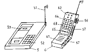
Cordless -telephones comprise a stationary part 5 with
connection to the power- and telephone grid, which includes
an aerial 51 and control lights 52 for various operating
conditions and the cradle 53 for the mobile part 6. This,
in addition to the microphone 61 and loudspeaker 62, further
includes a dialling device in the form of a keyboard area 63
~'
9 a
. ~ . .
,-.......... .
. -. : ",,
- . .: . . ~
03~
and further operating controls 64, like e.g. a disconnection
key, volume control etc. Due to that there is only little
free space on the inner sider of the receiver 6 for the
installation of the drive mechanism 65 of the dictaphone
5unit, as can be seen from fig. 3 a. Therefore one would
rather choose the embodiment shown in ~ig. 3 b, where the
drive mechanism 65 is situated on the outside of the
receiver 6. In the case of the aforementioned radio
communication sets, the stationary part 5 is inapplicable,
10at least during use..
Furthermore control lights can be provided to indicate
various functions. Individual or all of those lights can be
adapted to be switched on or off by means of an additional
switch so that it is possible to switch these on in the dark
15to more easily find the put down appliance.
Preferably a slider 66, or at least one push button, a
pressure sensitive pad or the like, which preferably is
situated on one of the narrow sides of the receiver 6 serves
to operate the dictation set analogous to the first
20embodiment. The power source for the dictating set, usually
accumulators, is also integrated into the receiver in both
described embodiments, in accordance with a further feature
of the invention. This entails that even in the case of a
necessary change of the power source the user need not
return to the basic appliance and therefore mobility is
maintained.
This advantage is further enhanced if - according to an
additional feature of the apparatus according to the
invention, the power source is re-charged by solar cells, or
~if these even provide the power supply during operation.
The installation ofthe dictating unit into a wireless
communication set can proceed analogously. Due to the
: - ,,: -
,:
3S
` increased available space on the front o~ the apparatusrepresenting the subunit 6, such installation can take place
on the front ~fig. 6).
Figs. 4 and 7 show a further embodiment for coupling the
5 dictation set 7 to the aforesaid subunit 4, 6, the receiver,
respectively the wireless telecommunication set, which,
however, can obviously also be applied to cord telephones.
The dictation set 7 is in that case slid into an aperture,
preEerably a lateral slot 69 of -the subunit 4, 6, and the
loelectrical contact elements may be provided inside the said
slot 69. Advantageously, the dictating set is inserted in
such a position that the operating controls remain
accessible, so that a second set of operating controls on
the receiver can be dispensed with. Fig.5,being a simple
15alternative embodiment to the aforegoing, represents a
connecting system, composed of rails 71 and grooves 45,
analogous to the embodiment of fig. 2.
Further embodiments of the apparatus according to the
invention are illustrated in figs. 9 a, 9 b and 9 c by way
of the example of a receiver 4 for a cord telephone. A
trough shaped depression 69' designed for the insertion of a
dictating set, is shown in all of the aforesaid
illustrations. In fig. 9 a moreover a releasable snap
mechanism is shown which fixes the dicating set in the
25depression. A catchlike component 80 which may essentially
extend over the entire length of at least one side of the
depression, for that purpose catches benind an edge or
groove on one or more sides of the dictating set. For
` releasing the fixation, a slider 81 or similar operating
means may be provided, which acts onto the component 80 and
by pivotal or rectilinear retraction effects disengagement
from the groove on the dictating set. Instead of a component
80 extending over essentially the entire length of one side
of the depression, it is e.g. also possible to provide a
~ 3t;
narrow pin or projection 82, as shown in fig. 9 b. If the
component 80,respectively the pin or projection 82, is not
made of rigid material,the action thereon by the slider 81
can be dispensed with and the fixation may be released by
5 lifting the dictating set and by elastic deformation of the
component 80, respectively 82.
In fig. 9 b, two hinged covers 83 and 83' are illustrated
for covering the depression 69', covering the entire area.
Fig. 9 c inally illustrates a furthe~r working example for a
10 cover according to the invention in the form of a plate
8S slidable in guide means 84.
The hinged cover 68, 83, 83' as well as the slidable plate
85 may be utilized in addition to or as alternatives to the
aforedescribed~means ~or fixing the dictating set on or in
15the subunit 4, 6. The aforesaid lateral slot 69 for the
introduction of the dictating set into the subunit 4, 6
described with reference to figures 4 and 6 may additionally
be provided with such cover means.
The installation of a magnetic fixing means may serve as a
0further example~for a possible m~eans for mounting or
securing the dictating set to the subunit 4, 6.
Electric contact is established by at least one contact
element 72, preferably a series of plugs or so-called
contact pins which engage after having brought about the
25complete mechanical connection with the corresponding
elements on the receiver. When the dictating set is
separated, the latter are preferably protected against
damage or dirt by a cover. This can be removed either
manually before fitting the dictating set, or automatically
30during the fitting process by any means, like levers,
sliders or simllar items, by the dictaphone ltself.
12
.
- :. -
.. :
' ~
3'~
Fig. 2 shows a modification with a lever 47, pushing
aside the cover 46.
In a manner analogous to that described so far for dictating
sets, other accessory apparatus may be integrated in the
5subunit or be coupled thereto by means of the above
described connecting systems. Even the simultaneous
application, respectively the simultaneous installation of
two or even more accessory instruments is possible under
favourable conditions and likewise the installation of one
apparatus inside the subunit and the coupling thereto to
such subunit of at least one further apparatus.
A radio receiver unit may, as illustrated in fig. 10 a, be
installed for example in the receiver 4 of a cord telephone.
~; Turning knobs 100 and 101 or similar control elements serve
5e g. for volume control, respectively the selection of the
transmitter station, and 102 denotes the frequencyl
respectively station indicating means. The loudspeaker 42 of
the subunit 4 may advantageously also serve for the radio
unit. When a radio apparatus 103 is coupled onto the
20receiver 4, as illustrated in fig. 10 b by means of the
above described groove and fixing rail system 45, 71, the
electrical connection is likewise established analogously to
; the afore explained design, preferably by way of contact
pins 72, and the turning knobs 100, 101 are, of course,
2sprovided on the radio apparatus 103. The contact elements
are preferably also protected by a removable cover 46.
In fig. 11 a, a wireless apparatus 6 is shown which in a
manner analogous to fig. 4 or 7, is designed for being
coupled to a personal call receiver 110, a so-called
30"pager". It is inserted into preferably a lateral slot 69 of
the subunit 6, and may be coupled by way of internal contact
elements to the subunit 6, in particular to the loudspeaker
62. In this context the pilot light 111 of the pager 110 may
13
~. :
2~ 3~
remain visible, although its ~unction may also be adopted by
a globe 112 on the component 6. In fig. 11 b, a wireless
apparatus 6 with integrated pager means is shown, in which
the globe 112 is notorious and also that operating means 113
5Of the pager 110 must be provided on the casing of the
subunit 6~ ~-
In correspondi~g and constructionally analogous manner, in
further developments of the inventive concept, apparatus may
for example be integrated in the subunit 4, 6, serving for
lOacoustic space monitoring ~"babysitter"-Eunction),
apparatus for the remote answering of alarm systems, sensors
etc. and other similar instruments incluaing the associated
operating means and control elements, or the subunit may be
designed for being coupled to the said accessory
15in5truments.
Finally, the integration, respectively coupling
of instruments with optical indicator means is possible.
Thus fig. 12 represents a receiver 6 for a cordless
telephone with an integrated electronic data storage means,
20also known as an electronic note*ook. 120 denotes the
display means for alpha-numeric symbols or where applicable,
special symbols, and for communication with the storage
means, the keyboard 63 already present, can be used, where
appropriate, with the inclusion of element 64. However, if
25space permits, a separate keyboard may also be provlded.
Fig. 13 finally illustrates as the last example a wireless
apparatus with built-in TV receiver. In that case, operating
elements, e.g. turning knobs 140 for adjusting the volume or
the brightness and the contrast o~ the display screen 141,
30and at least one element 142 ~or channel selection are
provided on the subunit 6. The sound is provided by way of
the loudspeaker 62 of the wireless apparatus 6.
..~ ,
2~ 35
It stands to reason that for fitting all of the aforesaid
apparatus, the modifications illustrated in figures 8 a to
9 c, using a dictating set as example, can also be used. The
same applies to the electrical contact elements and their
5 optionally provided cover means, which likewise may be
designed to be automatically removab]e by the appliances
when being coupled on.
The solar cells 67 for running the dictating set or any
other accessory instrument in the subuni-t, are connected
with each other in series and/or in parallel, according to
the number of accumulators in which context electronic
devices can be providad in the usual manner which prevent
an over- or undercharging, as well as discharging of the
accumulators by way of the solar cells. Likewise a DC to DC ~ 15convertor ~an be provided to increase, when necessary, the
charging voltage.
For additional surface area enlargement for positioning
solar cells, swing out panels 67' can be provided as shown
in fig. 5, which are linked to the subunit 4, 6 by optional
20hinge-like connections. These can accommodate further solar
cells 67 and can therefore increase the power output, at
least during the re-charging operation.
; Particularly ln the case of embodiments according to figs.
3 a and 3 b, and 5, the cordless telephone and also all
25similar appliances that are independent of a basic appliance
during operation, especially radio communication sets
(figs. 6, 7), solar cells 67 can be provided on the outside
of the receiver 6, but also in addition on the narrow sides.
The solar cells, provided they are suitably laid out, can
charge the dictating set as well as the accumulator of the
telephone unit leading to a reduced energy consumption from
the mains supply.
,,
)3~
Should a surface area with solar cells larger than that
offered by the receiver be necessary for charging, then,
instead of this being on the stationary part, it could also
be connected with a solar cell unitof the xequired size via
5charging contacts, which are designed analogously to the
contacts of the fixed part.
Although the power supply in the case o~ cordless telephones
according to fig. 1 can be brought about easily by the
existing connection to the power grid via the receiver
lOcable 3 and the basic appliance 1, the use of solar cells
also in this case offers the advantage of cost reduction
due to low consumption from the mains.
With cordless telephones, for reducing the weight of the
receiver, the power source can be provided also in the
15basic appliance 1, which also provides larger surfaces for
the installation of solar cells.
;
For optimal utilization of incoming radiation the most
modern solar cells are preferably used, such as the
recently developed fluid solar cells.
~These offer the advantage of storing the energy taken in
during the day and releasing it automatically at dark. Thus
by using these and/or a combination thereof with
conventional solar cells and appropriate dimensioning of
the surface ar~ea of the solar cells the operation of the
~appliance without energy consumption from the us~al energy
sources for such appliances is possible substantially for
the entire duration of use.
However, in order to safeguard the operation of the
appliances even under unfavourable light conditions, mains
- 30 adapters or chargers are preferably provided. In the case of
telephone- and dictation sets according to the cordless
16
:.- : - -
2~)~8~3~i
principle, these are preferably integrated into the receiver
6, the mobile component, or alternatively already existing
charging contacts, present in any case in the event of
cordless telephones, are used also for the dictating unit.
5For appliances according to the conventional cordless
telephone principle, the charging device, respectively the
mains component is pre~erably also accommodated in the unit
body.
To check the condition of the power source, a pilot lamp can
be provided which flashes when the appliance is in operation
and the available power is adequate. In the alternative
case, i.e. with run down power source, the pilot light does
not come on. Advantageously a further pi lot light can be
provided which flashes if the solar cells have taken over
15the power supply, or perform the charging of the power
source when the appliance is switched off.
Qne or both of these lights can be designed to be switched
on or off by means of an additonal switch so that it is
possible to switch these on in the dark to enable easier
20finding of the appliance, when put aside. On one of the
narrow sides of the appliance casing, the slider 5, or at
least one push button to operate the tape recorder is
situated. The remaining area on the long narrow sides as
well as between the intended parts on the upper side of the
25casing, may be used for the installation of solar cells 67.
On the bottom side of the casing additional solar cells can
be also provided, unless the space is required by the lid of
the battery or accumulator holder.
The sturdiness of the appliance can be enhanced by the
30 preferred application of protective coatings of transparent
but shatterproof material and this furthermore allows the
complete utilization of all empty surface areas on the
casing for the installation of solar cells. However, with
Z~ )3~
regard to handling, putting down, and transport, the degree
of caution must not be ignored which is normal with
conventional appliances of this kind.
Furthermore the complete utilization of the exposed sur~ace
5area is of advantage in that tape recorders of this lcind are
operated in various situations and positions. During the
recording oE discussions or telephone conversations e.g.
(through connection 9 for a telephone adapter) they mostly
rest with the bottom side on a support, wh;le, on the other
lOhand, they are often held in the hand such that in the
latter case a considerable part of the surface, mostly also
on the bottom side, is covered. For the power supply, during
operation of the tape recorder, solar cells on the upper-
and side areas of the tape recorder are thus of advantage,
5while the large area on the bottom side can be used, if not
in operation, to quickly recharge the accumulator, by
placing the appliance upside down, or rather pointing it in
the direction of strongest light radiation.
A further advantageous embodiment of the invention provides
20that the dictating set can optionally be switched on
manually, i.e. by means of a further control element to be
provided, or is automatically set into operation by incoming
calls, so that for safety sake every call is recorded.
In addition it is also possible by simple circuitry, to
25adapt the dictating unit as a telephone answering machine,
so that texts which have been recorded on the recording
medium, are played back and also room is provided for
messages of the caller on the inserted recording medium.
The playback of the stored information, or changing
30thereof, may, of course, also be carried out from any
desired other communication installation, respectively
telephone etc.. However, in order to prevent unauthorized
18
, ,
)35
persons from doing so, a further feature of the invention
provides the installation of a code recognition circuitry in
the recording and, respectively/or playback instrument 9,
which permits the aforesaid acts only after the input of a
5 recognition code.
In the modification involving an intercom installation, the
dictating set, similar to the function of a telephone
answering machine, can play back a message to a visitor
after the actuation of the doorbell or the like and/or may
10record and store a message from the visitor.
Preferably magnetic tape cassettes, optionally on a digital
basis, are used~as recording and storage medium. Diskettes,
compact discs etc. as well as non-interchangeable stGra~e
media, such as built-in endless tapes, solid state memories
15 or the like, can be used.
: .
For instruments in which secret information is contained on
the storage medium of the dictating set or even the
electronic storage means, it is sometimes desirable for
these to be destroyed before they can pass into unauthorized
2~h~ands. For that purpose, a further operating element may be
provided, which triggers the essentially simultaneous
erasure of the entire information on the storage medium.
What we claim is:
19
: . ~