Note: Descriptions are shown in the official language in which they were submitted.
20~82~9
VENTRICULOSTOMY RESERVOIR
BACKGROU~D OF T~E INVENTION
This invention relates generally to surgically
implantable valves. More particularly, this invention
relates to devices for the drainage of cerebrospinal
fluid from the ventricle of the brain and for
~ 5 monitoring such drainage.
;~ As is well known in the medical arts, to
relieve undesirable accumulation of fluids, it is
frequently necessary to provide a means--for draining a
fluid from one part of the human body to another in a
controlled manner. This is required, for example, in
the treatment of hydrocephalus, an ailment usually
- afflicting infants or children in which fluids which
;, ought to drain away accumulate within the skull and
3~ thereby exert extreme pressure and skull deforming
forces.
In treating hydrocephalus, cerebrospinal fluid
accumulated in the brain ventricles is drained away by
a catheter inserted into the ventricle through the
skull. The catheter is connected to a conduit which
conducts the fluid away from the brain to be
reintroduced into the vascular system, as by extending
`~ through the patient's jugular vein to the atrium
portion of the heart. To control the flow of
cerebrospinal fluid and maintain the proper pressure in
the brain ventricle, a pump or valve is placed in the
conduit between the brain and the heart atrium.
Examples of such pump and valve devices are shown in
U.S. Patent No. 4,560,375, to Schulte et al.
Ventriculostomy reservoirs are often utilized
in connection with such pumps or valves to provide a
convenient location for sampling accumulated
cerebrospinal fluid as close to the brain ventricles as
possible. Such ventriculostomy reservoirs may be
~ placed over a burr hole through the skull to facilitate
,,~ ' q~
. .
,
20~82~9
2--
;
sampling of cerebrospinal fluid before the implantation
of the fluid conduit.
Prior ventriculostomy reservoirs typically
include a metal base having a catheter connector, an
S integral, upwardly extending cylindrical wall portion,
and a flange portion integrally formed with and
overlying the wall portion. A cap made of a silicone
elastomer material i8 typically provided to enclose the
upper end of the base and define, with the base, an
internal reservoir. The cap usually includes an
annular internal recess configured to fit over the
flange portion of the base. -
The cap and the base of such prior
ventriculostomy reservoirs are usually separated prior
to implantation. The surgeon, after drilling a burr
hole through the skull, attaches a catheter to the
, connector at the lower end of the base, and then
I positions the base on the skull. Previously, the
surgeon has then been required to grasp the cap and
stretch its peripheral edges over the upper flange of
the base to position the flange within the recess of
the cap. This has, however, presented difficulties for
the surgeon which the present invention eliminates.
More particularly, during an operation the
2 s surgeon's gloves usually become guite slippery due to
contact with blood and other body fluids. This often
makes the grasping of ob~ects difficult, particularly
when the objects are very small. ~he caps of prior
ventriculostomy reservoirs also tend to become slippery
and dif~icult to handle when they have come in contact
with body fluids. This has made it difficult for
surgeons to quickly and efficiently grasp and stretch
the cap over the upper flange of the base.
Accordingly, there has been a need for a
convenient means for attaching the cap of a
ventriculostomy reservoir to the base, which renders
the device relatively inexpensive to manufacture and
which can be constructed substantially of non-metallic
., .
.. . .
. . . . ;.............. ~. -
::
20~8219
-3-
parts. Such a device would preferably suffer no
degradation in operation within a patient in comparison
with prior ventriculostomy reservoirs, and eliminate,
as much as possible, handling of the cap separately
from the base. In this regard it would be desirable to
provide means for connecting the cap to the base in a
manner providing a fluid-tight seal therebetween, which
; required nothing more than for the surgeon to push the
- cap onto the base at an appropriate time during the
surgical procedure. As will become apparent from the
following description, the present invention satisfies
these needs and provides other related ad~antages.
, .
~ SUMMARY OF THE INVENTION
::i
The present invention resides in a
ventriculostomy reservoir having improved assembly
characteristics, and which fulfills each of the needs
set forth above. The improved ventriculostomy
regervoir comprises, generally, a base configured to
provide an internal reservoir well, and a cap which is
positioned over the base to enclose the reservoir well.
The base includes an inlet and an upwardly extending
wall portion integrally formed with the inlet, and the
cap includes a dome portion and an outlet for the
reservoir. Neans are provided for attaching the cap to
the base to form a fluid-tight fit therebetween.
The attaching ~eans include~ a first means
associated with the base for connecting the base to the
cap, and a second means associated with the cap for
connecting the base to the cap. The first and second
connecting means cooperate with one another to form an
interference fit which prevents fluid leakage. In
forming this interference fit, the first and second
connecting means may include a detent provided in one
of the first and second connecting means, and a
protrusion provided on the other of the first and
t 35 second connecting means, wherein the detent and the
:
.,: .: . : .... , "
.; ~ ~ . . -:
", ~
~ . ,
4_ 20(~8219
- protrusion snap-fit together to securely hold the cap
to the base.
In a preferred form of the invention, the base
is formed of a rigid material such as polypropylene,
and is configured to provide an internal reservoir
well. This base includes a catheter connector defining
a reservoir inlet, and the wall portion is integrally
formed with the catheter connector and extends upwardly
therefrom. 2
The cap is preferably constructed of an
elastomeric material and is placed over the base to
enclose the reservoir well and define, with the base,
an internal reservoir. The cap includes a peripheral
supporting portion formed integrally with the dome
portion, and an outlet arm which defines an outlet
channel. The outlet arm i8 integrally formed with the
;i dome. Reinforced sheeting is attached to the dome
~- peripheral supporting portion in order to minimize
elastic stretching of a lower surface of the dome.
A rigid cap insert is securely affixed to the
;, cap and is positioned for engagement with the base.
The cap insert includes an annular flange-like portion
which is attached to the dome peripheral supporting
portion. The annular flange-like portion of the cap
insert includes a plurality of apertures filled with an
adhesive which tends to secure the cap insert to the
dome peripheral supporting portion.
In one illustrated embodiment, the base
includes a flange portion integrally formed with and
overlying the wall portion, which flange portion
includes an upper planar surface. The dome includes a
lower sealing surface which lies against the upper
planar surface of the flange portion of the base. The
~ cap insert includes a cylindrical portion which extends
.~ 35 dcwnwardly from the annular flange-like portion, and
this downwardly extending cylindrical portion fits
within the upwardly extending wall portion of the
rS base. The first connecting means includes an
.,
r:
~:,
.,, ' ' ' , ~. : :-
20(~8X19
encircling detent on an interior suxface of the wall
portion of the base, which is adjacent to the
cylindrical portion of the cap insert. The second
connecting means includes an encircling protrusion on
an exterior surface of the cylindrical portion of the
cap insert. Engagement between the protrusion and the
detent connects the cap to the base and forms a
fluid-tight seal therebetween.
In a second illustrated embodiment, the
' 10 annular flange-like portion of the cap insert is
captured within the dome peripheral supporting portion
to exteriorly surround an upper end of-the base. In
this embodiment, the first connecting means includes an
encircling detent on an exterior surface of the wall
portion of the base which is adjacent to and surrounded
h by the cap insert. The second connecting means
includes an encircling protrusion which extends
inwardly from the annular flange-like portion of the
cap insert. Again, the engagement between the
protrusion and the detent connects the cap to the base
and for~s a fluid-tight seal therebetween.
In a third illustrated embodiment, the annular
flange-like portion of the cap insert is attached to
the dome peripheral supporting portion to exteriorly
surround an upper end of the base. In this embodiment,
the base includes a flange portion integrally formed
with and overlying the wall portion, and the cap insert
i8 configured to exteriorly surround the base flange.
The cap insert i~ provided a detent which receives the
outer periphery of the base flange, and the cap insert
- further overlies the base flange and includes means
extending into the reservoir well for engaging an
interior surface of the wall portion of the base in an
; interference fit.
Other features and advantages of the present
- invention will become apparent from the following more
detailed description, taken in conjunction with the
accompanying drawings which illustrate, by way of
example, the principles of the invention.
, ,
.. . , :
,. , , . , ~ .. ,; .
2o~82l9
--6--
BRIEF DESCRIPTION OF THE DRAWINGS
` The accompanying drawings illustrate the
invention. In such drawings:
FIGURE 1 is a perspective view of one
~ preferred form of a ventriculostomy reservoir embodying
.~ 5 the invention, illustrated with an upper outlet tube
connected to a straight connector, and with a lower
inlet connector engaged by a catheter;
FIGURE 2 is an enlarged exploded perspective
s view of the ventriculostomy reservoir illustrated in
`~. 10 FIG. 1, illustrating the relationship--of the three
primary components thereof;
FIGURE 3 is an enlarged vertical section taken
generally along the line 3-3 of FIG. l;
.. FIGURE 4 is a vertical section taken generally
s. 15 along the line 4-4 of FIG. 3;
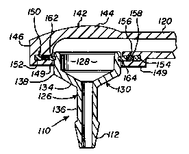
.. ~ FIGURE 5 is a vertical sectional view similar
to FIG. 4, of second embodiment of the ventriculostomy
reservoir of the present invention;
. FIGURE 6 is an exploded perspective view
similar to FIG. 2, of a third embodiment of the
ventriculostomy reservoir of the present invention; and
FIGURE 7 is a vertical section taken generally
along the line 7-7 of FIG. 6, illustrating an assembled
~ configuration of the third embodiment, and particularly
::; 25 the manner in which a cap insert surrounds an upper end
:. of a base to form an interference fit therewith and
. form a fluid-tight seal.
,:....
~ E~ILED DESCRIPTION OF THE PREFERRED EM80DIM~NTS
~'
~: As shown in the drawings for purposes of
illustration, the present invention is concerned with
an improved ventriculostomy reservoir, generally
~: designated in FIGS. 1 through 4 by the reference number
10, in FIG. 5 by the reference number 110, and in FIGS.
~, 6 and 7 by the reference number 210. These improved
.:.
:
.: , .. , ~. . . . . . .
~.' '. ';`, ~ '~ `" ' . ,.' '
- ` - 20082 1 9
--7--
,
ventriculostomy reservoirs lo, llo and 210 are intended
for use in a surgically implanted shunt system for
draining fluid from one portion of the human body to
another. In order to connect, for example, the
reservoir lo in such a system, the reservoir includes
an inlet connector 12 which receives one end of a piece
of surgical tubing or a catheter 14. The inlet tube or
~; catheter 14 slides over the inlet connector 12, and is
secured in place by a single ligature 16. The ligature
16 is preferably secured around the catheter 14 just
inside of an annular ridge 18 formed near the end of
the inlet connector 12. The reservoirs l~, 110 and 210
also include an outlet connector or arm 20 which is
3 dimensioned to receive a straight connector 22 or plug,
having an end resembling the inlet connector 12. The
outlet connector or arm 20 slides over the straight
connector 22, and is secured in place by a single
ligature 24 in the same manner that the catheter 14 is
secured to the inlet connector 12.
When the reservoirs 10, 110 and 210 are used
in a drainage system intended for treatment of
hydrocephalus, the inlet connector 12 and the catheter
14 are inserted through the skull into a brain
ventricle containing cerebrospinal fluid under
pressure. The outlet connector 20 connects to a distal
catheter (not shown) which serves to discharge
cerebrospinal fluid into, for example, the atrium
portion of a patient's heart. A suitable flow control
valve, ~or example either of those illustrated in U.S.
Patent No. 4,560,375, may be interposed in fluid communication between the
reservoir and the distal catheter. Ordinarily, the reservoir will be surgically
implanted on the patient's skull with a flap of skin overlying the reservoir.
Although three preferred forms of the
invention are illustrated in the accompanying drawings,
it is to be understood that each embodiment is the
, ,,~,, ,: :
20~8219
-8-
'
functional equivalent of the other. The reservoirs 110
and 210 shown in FIG. 5 and FIGS. 6 and 7,
respectively, simply illustrate alternative designs in
comparison with the reservoir 10 illustrated in FIGS. 1
..:
through 4. All three illustrated embodiments of the
f~ present invention provide a simplified and hiqhly
reliable ventriculostomy reservoir which is designed to
facilitate implantation and use thereof by a surgeon.
- They are each relatively easy to manufacture, are
quickly understood and easily assembled during a
surgical procedure.
In accordance with the present~-invention, and
as illustrated with respect to the first embodiment in
FIGS. 1 through 4, the reservoir 10 includes a
relatively rigid, unitized molded plastic base 26 which
is formed integrally with the inlet connector 12. The
base 26 i8 configured to provide an internal reservoir
well 28, and includes a wall portion 30 which extends
upwardly from the inlet connector 12, and a flange
portion 32 which is integrally formed with an overlies
; the wall portion. The wall portion 30 of the base 26
includes a lower frusto-conical section 34 which is
formed with a stem 36 of the inlet connector 12, and an
intermediate cylindrical section 38 which extends
between the flange portion 32 and the frusto-conical
section 34. The flange portion 32 includes an upper
planar surface 40.
;;, An elastomeric cap 42 is positioned over the
base 26 to enclose the reservoir well 28 and define,
with the base, an internal reservoir. The cap 42
includes a dome portion 44 which is integrally formed
with a peripheral supporting portion 46, and the outlet
connector or arm 20. The dome portion 44 is designed
to permit injection into the reservoir well 28 by a
hypodermic needle. When the cap 42 is placed over the
base 26, the base functions as a needle shield to
prevent a physician from inadvertently inserting the
needle too far, which could puncture the base and
extend beyond the limits of the reservoir well 28.
,s
:~
`
' .
- 2~ 19
g
In order to strengthen the cap 42 and
facilitate the forming of a fluid-tight seal between
the cap and the base 26, the cap is formed with a
planar undersurface 48 which faces the flange planar
surface 40. Reinforced sheeting 49 is adhesively fixed
to the cap planar undersurface 48, and abuts aqainst
the flange planar surface 40 to form a seal
therebetween. Moreover, a rigid cap insert 50 is
positioned within an annular channel 52 provided within
the peripheral supporting portion 46 of the cap 42,
which cap insert snap-fits into the base 26 to securely
hold the cap to the base and also form- a fluid-tight
seal therebetween.
More particularly, the rigid cap insert 50
includes an annular flange-like portion 54 which is
captured within the annular channel 52 of the cap 42.
As shown best in FIG. 2, the annular flange-like
portion 54 of the cap insert 50 includes a series of
apertures 56 which are filled with an adhesive 58. The
adhesive 58 tends to secure the annular flange-like
portion 54 within the peripheral supporting portion 46
of the cap 42. The cap insert 50 further includes a
cylindrical portion 60 which extends downwardly from
the flange-portion 54 and fits within the upwardly
2S extending wall portion 30 of the base 26.
In order to snap-fit the cap insert 50 into
the base 26, the wall portion 30, and more specifically
the cylindrical section 38 of the base, includes an
encircling groove or recess 62 on an interior surface
thereof, which i5 ad~acent to the cylindrical portion
60 of the cap insert 50 when inserted within the wall
.: portion 30. The cylindrical portion 60 includes an
.............. encircling protrusion 64 which is positioned and
.~ dimensioned to engage the grove 62 to connect the cap
42 to the base 26.
. This protrusion and recess arrangement for
connecting the cap 42 to the base 26 enables a
. physician to quickly and easily assemble the
.~ .
'', - `~ ;, , . ". '
: . , ~ ' ' -
, .
i
,. - , . ~ : ~ - ,: .
20~38219
--10--
ventriculostomy reservoir 10 during a surgical
procedure. During such surgical procedures a catheter
14 is often connected to the inlet connector 12, and
then the base 26 is positioned directly over a burr
, 5 hole through the patient's skull. To complete assembly
of the ventriculostomy reservoir 10, the physician only
~ needs to insert the cylindrical portion 60 of the cap
; insert 50 (which is preassembled with the cap 42), to
place the protrusion 64 within the recess 62. This
arrangement forms a fluid-tight seal, and eliminates
the requirement that the surgeon attempt to manipulate
the cap and stretch it over the flange-portion 32 of
the base 26. In the embodiment of FIGS. 1 through 4,
contact between the flange planar surface 40 and the
reinforced sheeting 49 attached to the cap planar
undersurface 48, tends to create a secondary seal which
` provides a backup against fluid leakage between the cap
42 and the base 26.
Many of these features are also provided in an
alternative second embodiment of the invention,
illustrated in FIG. 5, wherein functionally eguivalent
components common to both embodiments are referred to
in the drawings by corresponding reference numbers
increased by 100. Again, a rigid base 126 is formed
integrally with the inlet connector 112. The base 126
is configured to provide an internal reservoir well 128
and includes an upwardly extending wall portion 130
~; intQgrally formed with the inlet connector. More
particularly, the wall portion 130 includes a lower
frusto-conical section 134 which is formed with a stem
136 of the inlet connector 112. A cylindrical section
138 extends upwardly from the frusto-conical section
134. Unlike the first embodiment described in
connection with FIGS. 1 through 4, the embodiment of
FIG. 5 does not include a flange portion such as that
identified by the reference number 32 in connection
with the first illustrated embodiment.
.: ~
.
Z0~3219
--11--
An elastomeric cap 142 is positioned over the
base 126 to enclose the reservoir well 128. The cap
142 includes a dome portion 144 which is integrally
formed with a peripheral supporting portion 146, and
the outlet connector or arm 120. Further, reinforced
. sheeting 149 is attached to the undersurface of the
- peripheral supporting portion 146.
,.~ In order to connect the cap 142 to the base
126 in a manner forming a fluid-tight seal
therebetween, a rigid cap insert 150 is securely
positioned within an annular channel 152 provided
within the peripheral supporting portion-146 of the cap
142. The cap insert 150 includes an annular
- flange-like portion 154 which is positioned within the 15 annular channel 152. This annular flange-like portion
: 154 is nearly identical to that described above in
connection with the first embodiment, and includes a
plurality of apertures 156 which are filled with an
adhesive 158. The purpose of this adhesive 158 is to
. 20 secure the cap insert 150 within the dome peripheral
.. ~ supporting portion 146.
The ventriculostomy reservoir 110 illustrated
in FIG. 5 differs from the embodiment illustrated in
FIGS. 1 through 4 primarily in that the annular
:~; 25 flange-like portion 154 is positioned within the dome
.. peripheral supporting portion 146 to exteriorly
.. surround an upper end of the base 126. In this regard,
~ . an encircling recess 162 i5 provided on the exterior
.~. surface of the wall portion 130 of the base 126
.~ 30 ad~acent to the cap insert 150 when the cap 142 is
placed over the base 126. The cap insert 150 includes
an encircling protrusion 164 which extends inwardly
from the annular flange-like portion 154 towards the
base 126. The protrusion 164 is configured and
dimensioned to engage the recess 162 to connect the cap
142 to the base 126 and form a fluid-tight seal
therebetween.
.,
:
.. .
200~3219
-12-
A third embodiment of the invention is
illustrated in FIGS. 6 and 7, wherein functionally
equivalent components common to the first embodiment
illustrated in FIGS. 1 through 4, are referred to in
the drawings by corresponding reference numbers
increased by 200. The reservoir 210 includes a
relatively rigid, unitized molded plastic base 226
which is formed integrally with the inlet connector
212. The base 226 is configured to provide an internal
reservoir well 228, and includes a wall portion 230
which extends upwardly from the inlet connector 212,
and a flange portion 232 which is in~-egrally formed
with and overlies the wall portion. The wall portion
230 of the base 226 includes a lower frusto-conical
section 234 which is formed with a stem 236 of the
inlet connector 212, and an intermediate cylindrical
section 238 which extends between the flange portion
232 and the frusto-conical section 234. The flange
portion 232 includes an upper planar surface 240.
An elastomeric cap 242 is positio~ed over the
, base 226 to enclose the reservoir well 228 and define,
;~ with the base, an internal reservoir. The cap 242
;i includes a dome portion 244 which is integrally formed
with a peripheral supporting portion 246 and an outlet
connector or arm 220. The dome portion 244 is designed
to permit injection into the reservoir well 228 by a
. hypodermic needle. When the cap 242 is placed over the
base 226, the base ~unctions as a needle shield.
A rigid cap insert 250 i5 fixed to the cap
242. Like the other cap inserts described above, the
cap insert 250 snap-fits over the base 226 to securely
hold, by means of an interference fit, the cap to the
~, base and also form a fluid-tight seal therebetween.
More particularly, the cap insert 250 includes an
annular flange-like portion 254 which is attached to a
~` planar undersurface 248 of the cap 242. This annular
flange-like portion 254 is nearly identical to those
described above in connection with the first and second
.
, . . . ~ . .
.
,. :. - ..
.,
20~E3219
-13-
embodiments, and includes a plurality of apertures 256
which are filled with an adhesive 258. The purpose of
this adhesive 258 is to help secure the cap insert 250
to the dome peripheral supporting portion 246, as well
; 5 as to support a sheet of reinforced sheeting 249.
The annular flange-like portion 254 of the cap
insert 250 is positioned to exteriorly surround an
upper end of the base 226. The cap insert 250 has an
annular ring-like shape which in cross section
resembles a downturned ~U~. The cap insert 250
overlies the flange portion 232 of the base 226, and
includes a first cylindrical portion 266 which
encircles the periphery of the base flange portion 232,
and a second cylindrical portion 268 which extends
downwardly and fits within the upwardly extending wall
portion 230 of the base 226.
The first cylindrical portion 266 of the cap
insert 250 provides a detent 262 which receives therein
the outer periphery of the base flange portion 232.
The base flange portion 232 functions as a protrusion
264, in much the same manner as previously described in
. connection with the first and second embodiments. The
second cylindrical portion 268 of the cap insert 250
3 engages the interior surface of the wall portion 230 to
:~ 25 create an interference fit.
As with the other illustrated embodiments, to
assemble the ventriculostomy reservoir 220, the
'~ physician only needs to snap-fit the cap insert 250
(which is preassembled with the cap 242), over the
upper end of the base 226.
From the foregoing, it will be appreciated
that the reservoirs 10, 110 and 210 of the present
invention provided a device which permits sampling of
cerebrospinal fluid flowing directly from the brain
ventricle. Each of the ventriculostomy reservoirs 10,
110 and 210 can be fabricated conveniently and
economically, are trouble free and reliable in use, and
are easily assembled during a surgical procedure.
..
;~0~8219
-14-
While three particular forms of the invention
have been illustrated and described, it will be
apparent that various modifications can be made without
departing from the spirit and scope of the invention.
S Accordingly, it is not intended that the invention be
limit-d, xc-pt as by th- pp-nd-d claims.
~ .
:~ .
.~l
.,
.
",
, .
; . , -, .
. ~ ' . ' .