Language selection

Search

Patent 2008363 Summary

Third-party information liability

Some of the information on this Web page has been provided by external sources. The Government of Canada is not responsible for the accuracy, reliability or currency of the information supplied by external sources. Users wishing to rely upon this information should consult directly with the source of the information. Content provided by external sources is not subject to official languages, privacy and accessibility requirements.

Claims and Abstract availability

Any discrepancies in the text and image of the Claims and Abstract are due to differing posting times. Text of the Claims and Abstract are posted:

  • At the time the application is open to public inspection;
  • At the time of issue of the patent (grant).
(12) Patent Application: (11) CA 2008363
(54) English Title: TRANSPORT AND STORAGE CONTAINER FOR FLUENT MATERIAL
(54) French Title: CONTENEUR DE TRANSPORT ET DE STOCKAGE POUR MATERIAUX FLUIDES
Status: Deemed Abandoned and Beyond the Period of Reinstatement - Pending Response to Notice of Disregarded Communication
Bibliographic Data
(51) International Patent Classification (IPC):
  • B65D 61/00 (2006.01)
  • B65D 06/08 (2006.01)
  • B65D 19/10 (2006.01)
  • B65D 88/10 (2006.01)
(72) Inventors :
  • WENDLING, BRUNO (France)
  • HAMM, ANDRE (France)
(73) Owners :
  • SOTRALENTZ S.A.
(71) Applicants :
  • SOTRALENTZ S.A. (France)
(74) Agent: BORDEN LADNER GERVAIS LLP
(74) Associate agent:
(45) Issued:
(22) Filed Date: 1990-01-23
(41) Open to Public Inspection: 1990-08-05
Examination requested: 1997-01-15
Availability of licence: N/A
Dedicated to the Public: N/A
(25) Language of filing: English

Patent Cooperation Treaty (PCT): No

(30) Application Priority Data:
Application No. Country/Territory Date
P 39 03 392.9-22 (Germany) 1989-02-05

Abstracts

English Abstract


17418
Abstract of the Disclosure
A transport and storage container for flowable materi-
als comprises an annular and erect outer wall member in the form
of a gridwork of horizontal rods and vertical bars and having a
lower edge, a generally planar floor member having an outer edge
at the lower edge of the wall member and formed as a gridwork of
horizontal bars not unitary with any of the bars of the wall
member, and an inner vessel composed of a plastic material
enclosed by the outer support member and supported on the bottom
member. The bars of the planar floor member are separate from
and not unitary with the bars of the wall member and the rods of
at least one of the members have L-shaped end extensions that
extend past the respective edge and are joined to the rods of the
other member by welds. The upper edge of the wall member is
provided with an annular collar formed by a profiled steel
element welded to the tops of the steel vertical rods.


Claims

Note: Claims are shown in the official language in which they were submitted.

17418
EMBODIMENTS OF THE INVENTION IN WHICH AN EXCLUSIVE PROPERTY OR
PRIVILEGE IS CLAIMED ARE DEFINED AS FOLLOWS:
1. In a transport and storage container for flowable
materials comprising:
an annular and erect outer wall member in the form of a
gridwork of horizontal rods and vertical bars and having a lower
edge;
a generally planar floor member having an outer edge at
the lower edge of the wall member and formed as a gridwork of
horizontal bars not unitary with any of the bars of the wall
member: and
an inner vessel composed of a plastic material enclosed
by the outer support member and supported on the bottom member;
the improvement wherein
the bars of the planar floor member are separate from
and not unitary with the bars of the wall member;
the rods of at least one of the members have L-shaped
end extensions that extend past the respective edge and are
joined to the rods of the other member by welds.
2. The improved transport/storage container defined in
claim 1 wherein the L-shaped extensions are unitary with the
vertical rods of the wall member and are joined to the horizontal
rods of the floor member.

17418
3. The improved transport/storage container defined in
claim 1 wherein the L-shaped extensions are unitary with the
horizontal rods of the floor member and are joined to the verti-
cal rods of the wall member.
4. The improved transport/storage container defined in
claim 1 wherein every other vertical rod of the wall member has
such an extension welded to a respective horizontal rod of the
floor member and every other horizontal rod of the floor member
has such an extension welded to a respective vertical rod of the
wall member.
5. The improved transport/storage container defined in
claim 1 wherein the floor member is provided with pallet-type
feet element

Description

Note: Descriptions are shown in the official language in which they were submitted.


3~3
17418
TRANSPORT hND STORAGE CONTAINER FOR F~UENT MATERIAL
S~ECIFICATION
Eield of th~l nvention
The present invention relates to a transport and
storage container. More particularly this invention conc~rns
such a container for use with fluent material, that is a liquid
or particles.
Ba~kqround of the Invention
A storage and/or transport container or fluent materi-
al is known which comprises an erect and annular side w~ll and a
~lat and horizontal bottom wall joined together at the outer edge
of the ~ottom wall and lower edge of the side wall to form an
upwardly open vessel, and a flexible bag or bladder within this
vessel that lies against its 1nner surface and that itself
contains the material being transported or stored. The side and
bottom walls are typically made of round-section metal bars or
rods that are spot-welded together in a cross-c.rocsed gridwork
with the bars welded at the intersections. It is also possible
to use profiled bars and is in fact standard to provide a pro-
filed rim element around the upper edge of the side wall.

znO~33~3
17418
.4~requently extra bars are integrated lnto the bottom or side wall
for increa~ed localized stiffness.
In U.S. patent appllcation 07/422,~90 filed 16 October
1989 by G. Roser et al the vertical rods of the side wall are
bent over into the plane of the ~loor panel 80 that they form
this bottom pansl, additional reinforcement bars being added for
s~i~fness if desired. The bent-over bars and ~he laid-in ~ars
are welded to~etherO ~hismakes a very stable package that very
safely reCeivesthe contained bladder. Such an arrangement can
~e bu~lt relatively easily even by automated procedures.
Another system described in German patent document
3,839,999 is of substantially simpler construction. In it the
side wall and the bottom wall are fo~med o~ a ~ingle planar bar-
mesh sections. L-section ~plice Qlements are welded at the
corners between the side wall and botto~ wall. This conta~ner
can be built relatively easily by wholly automated equipment.
Ob~ects of the Invention
It is there~ore an object of the present invention to
provide an improved two-part storage and transport container.
Another object i8 the provision o~ such an improved
two-part storage and transport container which is a~ strong as
thQ above-described systems but which i8 ~ubstantially easier to
manufacture.

36~3
17418
Here described is a variation on a transport and
storage container for flowable materials comprising an annular
and erect outer wall member in the ~orm of a ~ridwork of horizon-
tal rods and vertical bars and having a lower edge, a generallyplanar floor member having an outer edge at the lower edge of the
wall member and formed as a gridwork of horizontal bars not
unitary with any of the bars o~ the wall member, and an inner
vessel composed of a plastic ~aterial enclosed by the outer
10 support me~ber and supported on the bottom member.
The bars of the planar floor member are separate
from and not unitary with the- bars o~ the wall member and the
rods of at least one of the members have L-~haped end extenslons
that extend past the respective edga and are joined to the rods
15 of the other member by welds. The upper edge of the wall member
is normally provided with an ann~lar collar formed by a profiled
steel element welded to the tops of the steel vertical rods.
The L-shaped exten-
sions are unitary with the vertical rods of the wall member and
are ~oined to the horizontal rod~ of the floor member. It ~g
also possible for the extensions to be unitary with the horlzon-
tal rods of the floor ~ember and to be ~oined to the vertlcal
rods of the wall member. In another arrangement every other
vertical rod of the wall member has such an extension welded to a
~5 respectlve horizontal rod of the floor member and e~ery other

~ 333~3
horizontal rod o~ the ~loor me~ber ha~ ~uch an exten~ion welded
to a raspective vertical rod of the wall member. The type o~
welding unit used to make the structure can deter~in~ which style
to use.
It ls also possible for -the
floor member to be provided with pallet~type feet element. These
can blocks welded to the bottom o~ the floor member or can be
integral gridwork feed formed unitarily from the rods or welded
to the rod~ of the floor member as in the above~described copend~
ing patent applicationO
More particularly, in accordance with the invention there
ls provided, in a transport and storage container for flowable
materials comprising:
an annular and erQct outer wall member in the form o~ a
gridworX o~ horizontal rod~ and vertica'l b3rs and having a lower
~dgQ;
a generally planar floor member having an outer edgs at
the lower edge o~ the wall member and ~ormed a~ a gridwork o~
horizontal bars not unitary with any o~ the bar~ o~ the wall
~e~ber; and
an inner ve~sel composed o~ a plastic material ~nclo~ed
by the outer support member and supported on the bottom msmber~
tha improv~ment wher~in
th~ bar~ o~ the planar floor member are separate from
and not unitary with the bars of the wall member;
the rods of at least one o~ the members hava ~-~haped
end extensions that extend past the re6pective edge and are
~o~ned to the rods o~ the other member by welds.
Embodiments of the invention will now be described, it being
understood that any feature described with reference to one
embodiment of the invention can be used where possible with any
other embodiment and that reference numeral~ or letter not
spec~fically mentioned with reference to one ~igurQ but ldentical

33~3
to those o~ another re~er to structure that is functionally i~
not structurally identical, In the accompanying drawlng~:
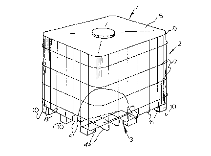
Fig. ~ 1B a small-scale perspeative view of the con-
tainer embodying this invention;
Fig. 2 is a perspective view of the wall member of Fig.
1 upside-down; and
Figs. 3 ~nd 4 are views like Fig. 2 o~ variations on
the system embodying this invention.
~Pec:i~ic~esçrl~orl
As see~ in Figs. 1 and 2 a transport/storage container
1 basically comprises an annular side
or wall me~ber 2, a floor member 3, and a bag liner 5. The wall
member 2 is formed of annular horizontal bars or rods 7 and
vertical rods 4 that are connected together in a gridwork and
wQlded together at their crossing~. The floor member 3 ~
comprised of horizontal rods 4' al80 connected togeth~r in a
gridwork and welded together at their crossings.
A pro~iled reinforcement member 9 is welded to the tops
o~ the vertical rods 4. In addition blocks 10 (shown only in
Fig. 1) can be installed at the corners and middles of th~ side~
of the floor member 3 to allow the system to be handled like a
pallet. These blocks 10 can be formed integrally.of the rods ~'
of the floor 3 or can be ~eparate elements. For clarity of Vi8W,
f~wer rods 4 and 4' are shown than are actually normally used.
In Figs. 1 and 2 the rods 4' of the ~loor 3 have curve~
generally L- haped extensions 6 each o~ who~e lower leg is
un~tary wLth and a continuation of the respectlve rod 4' and each
of whose ùpper legs is welded at 8 to a respective one o~ the
vertical rods 4 of the side member 2.

Z~3363
17418
Th~ system of Fig. 3 has corner extensions 6' that are
~nitary with the side-wall rods 4 and welded at 9 to the bottom-
wall rods 4'. In Fig. 4 extensions 6" are formed alternately of
the rods 4 and 4'.
:
:

Representative Drawing
A single figure which represents the drawing illustrating the invention.
Administrative Status

2024-08-01:As part of the Next Generation Patents (NGP) transition, the Canadian Patents Database (CPD) now contains a more detailed Event History, which replicates the Event Log of our new back-office solution.

Please note that "Inactive:" events refers to events no longer in use in our new back-office solution.

For a clearer understanding of the status of the application/patent presented on this page, the site Disclaimer , as well as the definitions for Patent , Event History , Maintenance Fee  and Payment History  should be consulted.

Event History

Description Date
Inactive: IPC from MCD 2006-03-11
Application Not Reinstated by Deadline 2001-01-23
Time Limit for Reversal Expired 2001-01-23
Deemed Abandoned - Failure to Respond to Maintenance Fee Notice 2000-01-24
Inactive: Status info is complete as of Log entry date 1997-07-04
Inactive: Application prosecuted on TS as of Log entry date 1997-07-04
Amendment Received - Voluntary Amendment 1997-07-02
Request for Examination Requirements Determined Compliant 1997-01-15
All Requirements for Examination Determined Compliant 1997-01-15
Application Published (Open to Public Inspection) 1990-08-05

Abandonment History

Abandonment Date Reason Reinstatement Date
2000-01-24

Maintenance Fee

The last payment was received on 1999-01-14

Note : If the full payment has not been received on or before the date indicated, a further fee may be required which may be one of the following

  • the reinstatement fee;
  • the late payment fee; or
  • additional fee to reverse deemed expiry.

Patent fees are adjusted on the 1st of January every year. The amounts above are the current amounts if received by December 31 of the current year.
Please refer to the CIPO Patent Fees web page to see all current fee amounts.

Fee History

Fee Type Anniversary Year Due Date Paid Date
Request for examination - standard 1997-01-15
MF (application, 8th anniv.) - standard 08 1998-01-23 1998-01-06
MF (application, 9th anniv.) - standard 09 1999-01-25 1999-01-14
Owners on Record

Note: Records showing the ownership history in alphabetical order.

Current Owners on Record
SOTRALENTZ S.A.
Past Owners on Record
ANDRE HAMM
BRUNO WENDLING
Past Owners that do not appear in the "Owners on Record" listing will appear in other documentation within the application.
Documents

To view selected files, please enter reCAPTCHA code :


To view images, click a link in the Document Description column. To download the documents, select one or more checkboxes in the first column and then click the "Download Selected in PDF format (Zip Archive)" or the "Download Selected as Single PDF" button.

List of published and non-published patent-specific documents on the CPD .

If you have any difficulty accessing content, you can call the Client Service Centre at 1-866-997-1936 or send them an e-mail at CIPO Client Service Centre.


Document
Description 
Date
(yyyy-mm-dd) 
Number of pages   Size of Image (KB) 
Claims 1994-03-01 2 49
Abstract 1994-03-01 1 25
Drawings 1994-03-01 2 56
Description 1994-03-01 6 193
Representative drawing 1999-07-29 1 14
Drawings 1993-11-01 2 56
Claims 1993-11-01 2 49
Abstract 1993-11-01 1 25
Description 1993-11-01 6 193
Courtesy - Abandonment Letter (Maintenance Fee) 2000-02-21 1 185
Fees 1997-03-17 1 53
Fees 1997-01-12 1 50
Fees 1996-01-08 1 36
Fees 1994-12-28 1 59
Fees 1993-12-22 1 21
Fees 1992-12-29 1 35
Fees 1992-01-22 1 26