Note: Descriptions are shown in the official language in which they were submitted.
BACKGROUND OE THE I~VENTIO-i~
Voice and sound synthesizing devices have been
long used in toys. Such toys are capable of providing
sounds responsive to positions in, for example, a doll or
a ball. These toys, however, are of little or no
educational value to the user.
One such toy, for example, comprises a doll as
disclosed in U.S. Patent No. 4,318,245, March 9, 1982, to
Stowel et al. The doll as disclosed by Stowel et al.
produces a variety of sounds responsive to positionina of
the doll by a child. The doll is able to make a specific
number of sounds, such as laughter and crying, but is not
capable of providing educational assistance to an infant
or child.
Another sound-produciny device is disclosed in
U.S. Patent No. ~,662,260, May 5, 1987, to Rumsey. The
Rumsey patent discloses a ball that is capable of
producing different notes responsive to positioning of the
ball. A person using the ball is capable of producing a
musical tune by positioning the ball in various locations
to se~uence the appropriate notes. The Rumsey device
provides no direct instruction -to the user and does not
serve as a learning aid.
Thus, there ls a need for a combined toy and
learning aid which is capable of educating infants through
adults in various visual displays matched with their sound
and/or an oral identification in a position-sensitive
educational format.
,
"
.
.
SUMMARY OF THE I~VEMTIOM
The present invention disclosed herein comprises
a method and apparatus for a position-sensitive
educational product. The present invention helps the user
to associate visual images with specific sounds and/or
their identification.
In accordance with one aspect of the invention,
a multisided container forms the e~terior shape of a toy.
Within the container is a power source such as a battery
and a microprocessor capable of synthesizing sounds and/or
voice. The position sensor indicates to the
microprocessor which side of the toy is in the "up"
position, and the microprocessor provides sound responsive
to a visual display on the "up" position.
lS In a preferred embodiment, the con-tainer
comprises a dodecahedron, and the position sensor
comprises five reed switches. The five reed switches
combine to provide a code to the microprocessor to
indicate the correct sound to be reproduced corresponding
to the "up" position.
It is a technical advantaye of the present
invention that a toy is provided which can educa-te infants
through adults. The toy can be positioned so that variety
of visual displays can be identified by an aural response.
The toy is adaptable to a variety of visual displays that
can be keyed to the level of development of a child or
young adult.
.
: . . , ` : , :`
:
BRIEF DESCRIPTIOM OF THE DRAWINGS
For a more complete understanding of the present
invention and for further advantages thereof, reference is
now made to the following Detailed Description, taken in
conjunction with the accompanying Drawings, in which:
FIGURE 1 is an exploded perspective of a
preferred embodiment of the present invention;
FIGURE 2 is an electrical schernatic illustrating
a circuit and a microprocessor used to produce an audible
response to a position indication;
FIGURES 3a-b are views of a position sensing
mechanism in accordance with the preferred embodiment of
the present invention;
FIGURES 4-12 are illustrations of alternative
embodiments of position sensincJ mechanisms constructed in
accordance with the present invention; and
FIGURE 13 is a perspective view of an
alternative embodiment of the toy of -the present
invention.
2S
,,
. ~ ~: ,.; ' : : :
,
DETAILED DESCRIPTION OF THE I~VE~ITION
.
In FIGUR~S 1-5, like items are identified by
like and corresponding numerals for ease of reference.
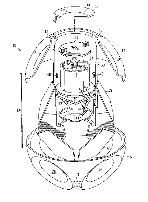
Referring to FIGURE 1, an exploded perspective view of a
toy constructed in accordance with the present invention
is generally identified by the reference numeral lO. The
toy lO comprises a container 12, haviny first and second
halves 14 and 16. The container 12 preferably comprises a
twelve sided polygon or a dodecahedron having twelve
10 planar faces 17-28 (only 19, 21, 22, 25 and 26 are shown
in EIG. 1). The planar faces 17-28 are provided with a
visual display which corresponds with a sound and/or a
voice produced by a microprocessor, as will subsequently
be described in yreater detail.
For example, -the toy lO is provided with a first
and second insert 29 and 30, which may have, for example,
animal displays (not shown) on each of the planar faces
17-28. The inserts 29 and 30 make it relatively simple to
replace the visual displays and still use the same
container 12. Alternatively, it is possible to provide
visual displays that are connected directly to a surface
of the planar faces 17-28.
The container 12 is constructed with a plastic
material that is nontoxic and is safe for the use of
infants. The first and second halves 14 and 16 are molded
to have smooth or rounded rather than sharp edges to
facilitate rolliny of the toy lO onto its various planar
faces 17-28. The first and second halves 14 ard 16 may be
secured together by any appropriate method SUCh as sonic
welding, yluing or astening with screws. The first and
second halves 14 and 16 are provided with a plurality of
.
:
.
,
6 ~ 3
apertures 13 to facilitate the transmission of sound
therethrough.
Access to the interior of the container 12 is
through a removable cap 32 which is coincident with face
5 20 and is preferably constructed to deny access except by
prying with a screwdriver or a coin. Within the container
12 is a battery pack 34, which may contain, for example,
four AA batteries, to provide power for the toy 10. A
cover 36 may be provided for the battery pack 34 to allow
10 for an on-off switch. The battery pack 34 is secured to
an inner support 38 by any appropriate method, such as
screws 40.
Secured to the inner support 38 adjacent the
battery pack 34 is a printed circuit (PC) board 42, which
15 contains circuitry and a microprocessor necessary to
enable the toy 10 to function, as will be subsequently
described in cJreater detai].. Opposlte the removable cap
32 and within the container 12 is a speaker 44. The
speaker 44 is interconnected to the PC board 42 via
20 electrical connections 46 and 48, which enable the speaker
a,4 to respond to the microprocessor. A position sensing
mechanism 50 (FIGURE 3) is interconnected to the PC board
42 to allow the microprocessor to know which of the planar
faces 17-28 of the toy 10 is in a predetermined
25 orientation or the "up" position (face 22 in FIGURE 1) in
which one of the faces 17-28 is uppermost.
In operation, when the toy 10 is moved, it
immediately turns on and begins playing musical notes
while being rolled or turned. If a child stops turning or
30 rolling the ball, a pleasant voice will announce the
identification of and a sound corresponding to the visual
::. ::
~:
7 2~
-
display on the planar face 17-28 which i5 in the "up"
position. For example, using the following visual display
arrangement:
face 17 = a dog; face 23 = a horse:
face 18 = a cat; face 24 = an owl;
face 19 = a duck; face 25 = a sheep;
face 20 = a cow; face 26 = a frog;
face 21 = a goose; face 27 = a chicken; and
face 22 = a pig; face 28 ~ a bird;
if face 19 having a duck picture is in the ~up~ position,
the toy 10 will state that a duck i.s shown followed by a
representative sound of a duck. Continuing the example,
if face 22 having a pig pictùre is turned to the "up"
position, the toy 10 wil.l state that a piy is shown
followed by a representative sound of a pig, and so on.
When the toy lO is moved again, musical notes
play until another visual display is recognized in the
"up" position by a pause in motion. As long as the toy 10
is rolled or turned, it will continue to respond with an
identification and representative sound of the visual .,
display in the llup" position. When the toy is not turned
or rolled for a brief period, a short musical signal wi.ll
play to reattract the child's attention. If there is no
further activity, the toy 10 will announce that it is
being turned off, which will then automatically occur.
Referring to FIGURE 2, an electrical schematic
illustrating the circuit and microprocessor used to
convert the output of the position sensing mechanism 50
into an aural response through the speaker 44 is
~. : . . : ,
-. . , ,, . . ~ , : :
. . . : i
ja 2 ~ 2 ~
illustrated. As shown in FIGURE 2, the position sensi.ng
mechanism 50 corresponds -to five switches 52, 54, 56, 58
and 60. The switches 52-60 correspond to five planes of a
dodecahedron, as will be subsequently described in greater
detail.
A microprocessor 62 is connected to switches
52-60 by pins PA0, PAl, PA2, PA3 and PA4, respectively.
The other contacts of each switch are connected to node
97. The microprocessor 62 is capable of decoding at least
twelve lines of encoded data, storing multiple sounds,
selecting one of the stored sounds correspondi~g to a
decoded signal and generating an audible sound in response
to the decoded signal. The audible sound is preferably of
an educational nature corresponding to a visual display on
the planar faces 17-28 (FIG. 1).
Pull-up resistors 64, 66, 68, 70 and 72 are
connected to pins PA0-PA4 and switches 52-60,
respectively. Resistors 64-72 may be on the order of 200K
ohms and are also connected to the cathode of a diode 74.
The anode of diode 74 is connected to a fuse 76, which is
connected to the battery pack 34, which provides, for
example, six volts. The fuse 76 protects the circuit from
shorts and the diode 74 prevents reverse battery damage.
Between node 78 and node 80 is a resistor 82
which may be on the order of 200K ohms. Between node 80
and node 84 is a capacitor 86, which may be on the order
of 12,000 picofarads. The node 80 is connected to the
anode of a diode 88 with the cathode of diode 88 connected
to the node 78. The collector of a transistor 90 which
may be of the pnp type is also connected to the anode of
the diode 88. The emitter of the transistor 90 is
-.: ~ , ........................ :, . ~
:' ;. , ' ~ . ', ' i ' `: ' , . -:
9 ~Jp~
connected to the microprocessor 62 at inverse INIT. The
base of the transistor 90 is connected through a resistor
92, which may be on the order of 82K ohms, to the
microprocessor 62 at PB0. A capacitor 93 which may be on
the order of 2200 picofarads is connected between a node
95 and a node 97.
The microprocessor 62 is powered by the battery
pack 34 through VDD and VSS. A capacitor 94 which may be
the order of forty-seven picofarads is installed between
node 78 and the node 97. A ceramic resonator 100 provides
clock to run the microprocessor 62 throuyh OSCl and OSC2.
Pins PA5-PA7 of the mlcroprocessor 62 are all coupled
together and connected to the cathode of diode 7~.
Speech output is transmitted to the speaker 44
through pins DAl and DA2. Pin DAl is connected through a
resistor 104 which may be on the order of 560 ohms to the
base of transistor 106 which may be of the pnp type. The
emitter of the transistor 106 is connected to node 78,
while the collector of the transistor 106 is connected to
a node 108. The collector of a transistor 110 which may
be of the npn type is connected to node 108. The emitter
of the transistor 110 is connected to the emitter of a
transistor 112 also of the npn type and to node 97. The
base of transistor 110 is connected to a node 116 through
a resistor 118, which may be on the order of 100 ohms.
The collector of transistor 112 is connected to the node
116 while the base of transistor 112 is connected to node
108 through a resistor 120, which may be in the order of
100 ohms.
Connected between nodes 108 and 116 i.s a
capacitor 122, which may be on the order of 10
.~ :, , .
.. - .
! ;
2 ~
microfarads. Also connected between nodes 108 and llh is
the speaker 44 which is preferably on the order of 8 ohms.
The emitter of a transistor 123 which may be of the pnp
t~pe is connected to node 78, while the collector of
5 transistor 123 is connected to the node 116. The base of
transistor 123 is connected to the output DA2 of
microprocessor 62 throu~h a resistor 124, which may be on
the order of 560 ohms. The four transistors 106, 110, 112
and 123 form an amplifier for the speaker 44 and the
capacitor 122 provides a filter.
In operation, when switch 60 is activated, the
initialization circuit comprising the resistor 82, the
capacitor 86, the diode 88, the transistor 90, the
resistor 92 and the capacitor 93 ac-tivates the
microprocessor 62 to play a musical tune. When the switch
60 yoes ~rom open to closed position, a neyative voltage
spike occurs throuyh the capacitor 86. If the toy 10 is
powered down, the neyative spike will yo throuyh the
transistor 90 and triyger the inverse IMIT causing the
microprocessor 62 to turn on. If the microprocessor 62 is
already on, the transistor 90 wlll be off and the negative
trigyer wlll not reach the microprocessor 62. The
capacitor 93 is present to prevent noise from causiny an
interrupt to the microprocessor 62. As various switches
25 52-60 are activated, the microprocessor 62 interprets the
code provided thereto and transmits the appropriate aural
response to the speaker 44. After a set period of time,
when no switches 52-60 are activated, the circuit will
automatically shut down after a warning.
It would also be possible to place a software
option in the microprocessor to automate a quiet mode
'
i
:
.
11 2~ 23
rather than a mechanical on/off switch. Such an option
could provide a specific sequence of repositioning the toy
(such as turning back-and-forth from a picture of an owl
to a picture of a cow three times) to -turn the toy off
until the sequence is reversed (or another sequence is
initiated). This would allow an adult to shut the toy off
and leave it with a sleeping infant without fear of
accidentally turning the toy on.
Referring to FIGIJRE 3a, a top plan view of a
position sensiny mechanism constructed in accordance with
the preferred embodiment of the present invention is
generally identified by the numeral 5Q. As used herein, a
position sensing mechanism means a device capable of being
oriented by gravity with respect to the center of the
earth. The sensing mechanism 50 comprises five slide
tubes 126 mounted on the PC board 42. Proximate each
slide tube 126 is a reed switch 136 (FIGURE 3b) mounted on
the PC board 42 which is mounted within the second half 16
of the container 12. Each slide tube 126 is arranged to
be perpendicular to one of the planar faces 17-28 of the
container 12 and are oriented 72 degrees apart, as
indicated by angle X. In the example shown in FIGURE 3a,
the planar faces 23-27 each have a tube 126 perpendicular
thereto.
Referring to FIGURE 3b, a slide tube 126 is
shown in cross-section. The slide tube 126 comprises a
hollow tube 128 containing a magnet 130. The. slide tube
126 is maintained at an approximate angle Y from the PC
board 42. If the container 12 is a dodecahedron, the
angle Y is pre~errably between twenty-three and
twenty~seven degrees. The slide tube 126 is secured to
.. .. . .
. :~
:, , . ,: ' ~. ' :
,
' ' ' ' ,. : ;,. : :
12
the PC board a2 by any appropriate method, such as
supports 132 and 134. Mounted below the hollow tube 128
is a reed switch 136 which is connected by any appropriate
method, such as wire 138 to an electrical circuit as
previously described above with reference to FIGURE 2.
As the -toy 10 is positioned on its various
planar faces 17-28, the magnet 130 within the hollow tube
128 slides toward or away from the reed switch 136. ~1hen
the magnet 130 is proximate the reed switch 136, a signal
is sent through the wire 138 to the microprocessor 62
indicating a closed circuit. ~1hen the magnet 130 slides
away from the reed swltch 136, an open circuit response is
provided to the microprocessor 62.
Since there are five switches, there is a
possihility of 32 combinations of signals to be sent to
the microprocessor 62 of which only twelve are active. If
the toy 10 were designed to present visual displays of
animals, a possible sequence of coded signals would be as
follows:
25
.. , . ~ , . .. .
' ~ ' ` ' : ' :
12a
Switch Mo. 60 58 56 54 ~2 1 = Open
O = Closed
O O O O O Face 17 Dog
O O O 0
O O O 1 0 --~
O O O 1 1 Face 21 Goose
O 0 1 0 0
O 0 1 0 1 --
O O 1 1 0 Face 22 Pig
O O 1 1 1 Face 24 Owl
0 1 0 0 0
0 1 0 0 1 ---
0 1 0 1 0
O 1_ 0 1 1 ----
O 1 1 0 0 Face 18 Cat
-
0 1 1 0 1 ---
O 1 1 1 0 Face 23 Horse _
0 1 1 1 1 ---
0 0 0 1 ---
1 0 0 0 1 Face 20 Cow
0 0 1 0 ---
-
1 0 0 1 1 Face 25 Sheep
0 1 0 0 ---
0 1 0 1 ---
0 1 1 0 ---
0 1 1 1 ---
1 1 0 0 0 Face 19 3uck
1 1 _ O O 1 _ Face 26 Frog
0 1 0 ---
0 1 1 ---
-
1 1 1 O O Face 27 Chicken
-
0 1 ---
0 - -
1 1 1 1 1 Face 28 Bird
-
~ . . . . .. ~ ~ . ..
; , : :: : :
` 13 ~ J~
, _,
Using the above decoding -table, the
microprocessor 62 will be able to determine which planar
surface 17-28 is in the "up" position, and the correct
aural response will be produced.
Alternatives to the reed switches may be used in
the same confi~uration as shown in F~GURE 3a. One such
alternative is shown in FIGURE 4, in which a conducti~e
ball 140 rolls within a hollow tube 142. The hollow tube
142 may be either a metal conductor with a second contact
on the PC board 42 or plastic with two contacts on the PC
board 42. The contact 146 is interconnected to an
electrical circuit and the microprocessor 62 as previously
described above. Alternatively, the conductive ball 140
could comprise a conductive liquid such as mercury or
lS sodium pottassium.
Another alternative to the reed switches is
illustrated in FIGURE 5. A hollow tube 148 has an opaque
weiyht 150, which is free to move therein by gravity. The
opaque weight 150 may comprise, for example, a ball
bearing or an opaque liquid. A light transmitter 152
which may comprise on infrared light is positioned on the
PC board 42 directly opposite a light detector 156 wikh
the hollow tube 148 is between the transmitter 152 and the
detector 156. The hollow tube 148 may either be formed
from a clear material which will allow light from the
transmitter 152 to pass therethrough, or provided with
appropriate windows to allow passage of light
therethrough. When the toy 10 is positioned so that the
opaque weight 150 blocks the detector 156 from the
transmitter 152, an open signal will be given to the
. microprocessor 62. When the tube 148 is orlented so that
,':;, ' ': : - : , .~.
: : , : :
.,
: . :: :
14
opaque weiyht 150 does not block the receiver 156 from the
transmltter 152, a closed siynal will be transmitted to
the microprocessor 62.
Referriny to FIGURE 6, another alternative to
the reed switches of FIGURE 3b is illustrated in
cross-section. A hollow tube 158 is mounted on the PC
board a2. Within the hollow tube 158 is a reflective
weiyht 162, such as a chrome ball. Positioned within the
tube 158 is a reflective optical switch 164. The switch
164 transmits a liyht beam into the tube 158, and if the
reflective weiyht 162 is positioned proximate switch 164,
the light will be reflected therefrom into the receiving
portion of switch 164, providing a closed signaL to the
microprocessor 62. If the reflective weight 162 i9
positioned distaL the switch 164, the light will not be
reflected therefrom, and an open signal will be sent to
the microprocessor 62.
Referring to FIGURE 7, another alternative to
the reed switch of FIGURE 3~ is shown in perspective view.
20 A magnet 166 is positioned within a track 168. The maynet
166 is positioned so that a north pole 170 and a south
pole 172 are positioned on opposite sides of the track
168. Fixed to the track 168 is a magnetic sensor 174,
such as a Hall-Effect sensor. The track 168 is fixed to
25 the PC board 42 by a support 178. When the magnet 166 is
proximate the sensor 174, the south pole 172 activates the
sensor 174, indicating a closed position to -the
microprocessor 62. When the magnet 166 is distal the
sensor 174, the sensor l7a is turned off, sending an open
signal to the microprocessor 62.
:: : :.
: .
.
29~ 2~
In an alternative embodiment, it would be
possible to replace the five switches as shown above with
reference to FIGUREs 2-7 with one switch for each planar
surface 17-28 of the toy 10. One embodiment for such an
alternative is shown in cross-section in FIGURE 8. The
container 12 is fitted with an inner sphere 180 containing
a conductive liquid 182. The sphere 180 is not completely
filled with the liquid 182 and thus, an air bubble 184 is
formed. Position-sensing contacts 186, 188, 190, 192, 194
10 and 196 are formed within the sphere 180 perpendicular to
each of the planar faces of the container 12 (only six
shown in FIGURE 8). When the container 12 is placed on
one of its planar faces 17-28, one specific
position-sensiny contact, for example, contact 186 is
within the air bubble 184. Since all -the position-sensing
contacts except contact 186 are indicated as closed, the
microprocessor (not shown) knows that contact 186 is in
the "up" position, and the appropriate aural response is
emitted.
Referring to FIGURE 9, an alternative to the
sphere and ].iquid of FIGURE 8 is shown in cross-section.
An inner container 198 having a shape that matches the
container 12 is formed therein. The inner container 198
is positioned to place a planar junction perpendicular to
25 each of the planar surfaces 17-28 of FIGURE 12, forming
receptacles 200, 202, 204, 206, 208 and 210 (the inner
container 198 would have a total of twelve receptacles).
A conductive ball 212 is free to move within the inner
container 198. When the container 12 is positioned to
place the conductive ball 212 in one of the receptacles
200-210, a signal is sent to a microprocessor (not shown)
t'
'
'' , . ' , ~ ': ` '~
,
.
16 2~
indicating a closed position. The microprocessor then
knows that the planar surface directly opposite is in the
"up" position, and the appropriate aural response is
emitted. Alternatively, the inner container 198 could be
a sphere with contacts perpendicular to the planar
surfaces of container 12. When the conductlve ball 212 is
positioned in one of the appropriate receptacles, a closed
position is indicated to a microprocessor; otherwise, an
open position is indicated.
Referring to FIGURE lOa, another alternative
embodiment or the position~sensing mechanism 50 is
illustrated in cross-sectional view. A conductive housing
214 is filled with a conductive liquid 216, such as, for
example, sodium potassium or mercury. A base 218
comprises an insulator such as glass. Metallic leads 219,
220, 222, 224 and 226 (FIGURE lOb) extend through the base
218 and into the conductive liquid 216 on one side and
onto an appropriate circuit on a PC board (not shown) on
another side. As a toy lO is turned onto various planar
faces, various combinations of conductive leads 219-226
will be connected to the conductive housing 214 by the
conductive liquid 216. In accordance with a code, a
microprocessor will be able to determine which of the
planar surfaces is in the "up" position, and the proper
aural response will be emitted. Referring to FIGURE lOb,
the conductive housing 214 is shown to be circular in
shape when viewed from a top plan view.
Referring to E'IGURE 11, another alternative
embodiment of the position sensing mechanism of the
present invention is illustrated in cross sectional view.
An inner container 228 has a shape that matches the
~, :
~ ,:
,
2 3
container 12. The planar surfaces of the inner container
228 match with the planar surfaces 17-28 of the container
12. The container 228 is hollow and contains a light
source 230, such as strobe lights. An opaque substance
232, such as sand or small metallic particles are free to
move within the inner container 228. Directly opposite
each planar surface of the inner container 228 and the
container 12 are light receivers 234, 236, 238, 240, 242
and 244 (if container 12 is a dodecahedron, there ~ill be
twelve receivers). As the container 12 is placed on one
of the planar surfaces 17-28, the opaque substance 232
settles by gravity to the lowest point. The opaque
substance will not permit light from the light source 230
to pass therethrouyh to -the appropriate light receiver,
such as, for example, light receiver 236. A
microprocessor (not shown) interconnected via appropriate
circuitry to the light recelvers 234-244 is thus signalled
that the planar surface opposite receiver 236 is in the
"up" position, and the appropriate aural response is
emitted.
Referring to FIGURE 12, a still further
alternative embodiment of a position-sensing mechanism in
accordance with the present invention is shown in
cross-section. A conductive metallic ball 246 is
25 positioned within the container 12. Rigidly suspended
from the planar surfaces of the container 12 and
perpendicular to each planar surface are sensors 250, 252,
254, 256, 258 and 260 (if the container 12 is a
dodecahedron, there will be a total of twelve sensors).
As the container 12 is placed on one of the planar
surfaces 17-2~, the conductive ball 246 is pulled by
'~ ' i ' '
", '' ',
18
gravity towards one of the sensors, for example, sensor
254. A microprocessor (not shown) which is interconnected
to the sensors 250-260 is then signaled Vicl an appropriate
code that the sensor 260 directly opposite sensor 254 is
in the "up" position, and the appropriate aural response
is emitted.
Referring to FIGURE 13, an alternative
embodiment of the present invention is shown in
perspective view. A six-sided regular prism 262 is fixed
'oy a bracket 264, and an appropriate connection device 266
to the bars 268 of a cradle or crib. A child may turn the
six-sided regular prism 262 into various positions, ~hich
would be detected by a position sensing mechanism and
would result in an appropriate aural response being
lS emltted therefrom. The six-sided regular prism 262 would
be adaptable to be removed from the bars 268 and placed on
the floor or placed into an appropriate pull-toy
configuration, if desired.
The educational toy of the present invention is
capable of adaptation to use by infants, as well as older
children and adults. It is possible to provide the planar
surfaces of the container with appropriate visual images
for various age levels and to provide a microprocessor
capable of emitting sound and/or voice responses thereto.
With the addition of appropriate software, it would be
possible to use the educational toy as a game piece, such
as a talking die or a talking globe.
Although the present invention has been
dascribed with respect to a specific preferred embodiment
thereof, various changes and modifications may be
suggested to one skilled in the art, and it is intended
. ,, . ~ :
' ; : , '` ~ ~
:,
- . ,
'' ~ ''`'~ '
' : ''
'
19 2~ 3
.
that tlle present invention encompass such changes and
modifications as fall within the scope of the appended
claims.