Language selection

Search

Patent 2009880 Summary

Third-party information liability

Some of the information on this Web page has been provided by external sources. The Government of Canada is not responsible for the accuracy, reliability or currency of the information supplied by external sources. Users wishing to rely upon this information should consult directly with the source of the information. Content provided by external sources is not subject to official languages, privacy and accessibility requirements.

Claims and Abstract availability

Any discrepancies in the text and image of the Claims and Abstract are due to differing posting times. Text of the Claims and Abstract are posted:

  • At the time the application is open to public inspection;
  • At the time of issue of the patent (grant).
(12) Patent: (11) CA 2009880
(54) English Title: MECHANISM FOR INVERTING CARRIER
(54) French Title: MECANISME POUR RENVERSER UN CHASSIS PORTEUR
Status: Expired and beyond the Period of Reversal
Bibliographic Data
(51) International Patent Classification (IPC):
  • B65G 17/16 (2006.01)
  • B65G 47/252 (2006.01)
  • B65G 47/38 (2006.01)
(72) Inventors :
  • OSHIDA, MAMORU (Japan)
  • OIZUMI, MASARU (Japan)
  • ICHIZAWA, YOSHIYUKI (Japan)
(73) Owners :
  • YOSHINO KOGYOSHO CO., LTD.
(71) Applicants :
  • YOSHINO KOGYOSHO CO., LTD. (Japan)
(74) Agent: MARKS & CLERK
(74) Associate agent:
(45) Issued: 1998-07-07
(22) Filed Date: 1990-02-13
(41) Open to Public Inspection: 1990-08-14
Examination requested: 1995-01-27
Availability of licence: N/A
Dedicated to the Public: N/A
(25) Language of filing: English

Patent Cooperation Treaty (PCT): No

(30) Application Priority Data:
Application No. Country/Territory Date
1-34078 (Japan) 1989-02-14

Abstracts

English Abstract


An inverting mechanism according to the present
invention comprises an inverting body for inverting which
includes a plate member fixed to each of a plurality of
carriers connected to an endless chain and four inverting
elements rotatably supported on each plate member at
circumferential positions spaced equidistant from each
other, and an inverting cam provided on a rack rail on
which the inverting elements roll. The inverting element
on the body traveling on the rail drops into a groove
formed in the inverting cam to rotate the body about the
dropped inverting element as another inverting element
rolls along a projection on the reversing cam to downwardly
direct the top opening of the carrier and thereby an
article to be transferred can be taken out of the carrier.


French Abstract

La présente invention porte sur un mécanisme de renversement constitué d'un corps renverseur qui comprend une plaque fixée à chacun des châssis porteurs raccordés à une chaîne sans fin et quatre éléments renverseurs appuyés de façon à pouvoir tourner sur chaque plaque à des positions circonférentielles équidistantes, et d'une came de renversement posée sur un rail denté sur lequel roulent les éléments de renversement. L'élément de renversement sur le corps se déplaçant sur un rail tombe dans une rainure que comporte la came de renversement pour faire tourner le corps autour de l'élément de renversement tombé dans la rainure alors qu'un autre élément de renversement roule le long d'un bossage sur la came pour diriger vers le bas l'ouverture supérieure du châssis porteur, et ainsi un article à transférer peut être sorti du châssis porteur.

Claims

Note: Claims are shown in the official language in which they were submitted.

The embodiments of the invention in which an exclusive
property or privilege is claimed are defined as follows:
1. A mechanism for inverting a carrier in which a
plurality of carriers are connected to an endless chain and
transferred along a loop track, the mechanism comprising:
a body for inverting, which includes a plate member fixed
to each carrier and at least four inverting elements
rotatably supported on the plate member at circumferential
positions spaced equidistant from each other; and
at least one inverting cam including at least one
projection formed on a track rail on which the inverting
elements of the body roll, to guide the inverting elements
so as to invert the body, and grooves formed in the track
at the front and rear sides of the projection.
2. The mechanism according to claim 1, wherein the
track rail is provided with at least two inverting cams.

Description

Note: Descriptions are shown in the official language in which they were submitted.


CA 02009880 1998-04-01
MECHANISM FOR INVERTING CARRIER
The present invention relates to a mechanism for
taking an article to be transferred out of a barrel shaped
carrier, having a bottom, such as a bucket or the like, by
inverting the carrler to automatically drop the article out
of the inverted carrier by its own weight.
Hitherto, as a means for taking an article out of a
carrier in a conveyance apparatus comprising a plurality of
barrel shaped carriers for receiving articles to be
transferred, each of which having a bottom, such as a
bucket or the like, and one or two endless chains connected
to the carriers and arranged so as to travel along a loop
track, it is known that the endless chain may be arranged
so that the carriers connected to the chain travel along a
loop track in a vertical plane to provide an upper portion
in which the carriers progress in a normal posture and a
lower portion in which the carriers return in an inverted
posture to thereby let the articles in the carriers drop
out of the carriers by their own weight at the lower
portion of the endless chain.
Moreover, there are other well known arrangements for
taking the article out of the carrier by use of an
additional grasping device.
However, the conventional arrangements for dropping
the article out of the carrier, so connected, is limited to
the case where the carriers and articles travel along the

CA 02009880 1998-04-01
loop track in the vertical plane and can not apply to a
case of traveling in a horizontal plane.
Furthermore, the arrangement for taking the article
out by use of the additional grasping device requires high
cost of equipment and is expensive.
Summary Of The Invention
It is an object of the present invention to eliminate
the aforementioned disadvantages and to provide an
inverting mechanism adapted for easily and economically
taking an article out of the carrier irrespective of
whether the endless chain, the carriers and the articles
travel along a loop track in a horizontal or vertical
plane.
The present invention will be hereinafter described in
more detail with reference to the accompanying drawings, in
which:
Brief Description Of The Drawings
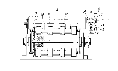
FIG. 1 shows a schematic elevational view of an
embodiment of the present invention, and
FIG. 2 is a diagrammatic view illustrating the motion
of the reversal body.
According to the present invention, a mechanism for
inverting a carrier comprises a body 1 to be inverted and
an inverting cam 2.

CA 02009880 1998-04-01
The body 1 includes a plate member 3 fixed to a
carrier 8, such as a bucket, connected to an endless chain,
and four inverting elements 4 which are rotatably supported
on a plate member 3 at circumferential positions spaced
equidistant from each other.
The inverting cam 2 includes a projection 5 formed on
a track rail 9 on which the inverting elements 4 of body 1
roll to guide the inverting elements 4 so as to invert the
body 1, and grooves 6 formed in the track rail at the front
and rear sides of projection 5.
The function of the present invention will be now
described by reference to FIG. 2 of the accompanying
drawings.
First, at "A" position, body 1 travels with two
inverting elements 4 (a third inverting element 4-3 and a
fourth inverting element 4-4) rolling on rail 9. At this
time, the bucket or carrier 8 fixed with body is maintained
in the normal posture with the top opening being upwardly
directed and an article 13 to be transferred being
contained in carrier 8. The top opening of the carrier is
shown by a straight line connecting two inverting elements
4 in FIG. 2: for example, at "A" position, the straight
line connected the first inverting element 4-1 and the
second inverting element 4-2.
When body 1 reaches "B" position as the carrier
maintains the normal posture, the fourth inverting element

CA 02009880 1998-04-01
4-4 drops in groove 6 to abut against projection 5 ("C"
position). As carrier 8 progresses further, body 1 begins
to rotate counterclockwise about the fourth inverting
element 4-4 until the first inverting element 4-1 abuts
against projection 5.
After the first inverting element 4-1 abuts against
projection 5, carrier 8 progresses further and then the
fourth inverting element 4-4 rises out of groove 6 and
travels along projection 5. At this time, the first
inverting element 4-1 also travels along projection 5 as
body 1 continues its inverting movement. When the first
inverting element 4-1 drops in groove 6, body 1 begins to
rotate about the first inverting element 4-1 in the
counterclockwise direction ("D" position). This inverting
movement continues until the second inverting element 4-2
contacts the surface of rail 9, and after the second
inverting element contacts the surface of rail 9, body 1
progresses as the first inverting element 4-1 and the
second inverting element 4-2 roll on rail 9 ("E" position).
At this time, the posture of body 1 is in an inverted
posture rotated from the original posture of body 1 ("A"
position), and therefore, the posture of carrier 8 is also
inverted and the top opening of the carrier is directed
downward.
Consequently, article 13 drops out of carrier 8 by its
own weight and is taken out of carrier 8.

CA 02009880 1998-04-01
A further inverting cam may be provided on rail 9 to
reinvert inverted body 1, thereby returning inverted
carrier 8 to the normal posture.
Preferred Embodiment Of The Invention
FIGS. 1 and 2 illustrate a particular embodiment of
the present invention. Specifically, FIG. 1 illustrates a
portion of an electron beam irradiating conveyance
apparatus for irradiating an article to be transferred,
such as a preform of a container of synthetic resin, with
an electron beam to remove monomer which adversely affects
a content in the container.
The conveyance apparatus comprises a plurality of
carriers 8 such as buckets which are spaced equidistant
from each other and connected to an endless chain 7 which
travels along a loop track in a horizontal plane, a
plurality of rollers 10 which are arranged directly under
the carriers each having a plurality of lands 11 which
intrude into carrier 8 through bottom openings 12 to
drivingly contact the article to be transferred so that the
rollers rotate the article in the carrier as the rollers
are rotated and moved along at the same speed and in the
same direction as are the carriers 8, and an electron beam
accelerator in an electron beam irradiation area arranged
directly above the carriers 8 which are cooperated with the
rollers which carriers 8 and rollers are arranged to pass

CA 02009880 1998-04-01
under the electron beam accelerator. Thus, the articles to
be transferred are uniformly irradiated with the electron
beam as the articles are transferred by means of carriers 8
and rotated by means of the rollers 10. The mechanism
according to the present invention is applicable to an
irradiating conveyance apparatus mentioned previously.
However, the present invention is not limited to such an
application for the conveyance apparatus.
The mechanism according to the present invention
comprises a body 1 used for inverting which is fixed to an
outer end of a fixed shaft 14 extended from one end of the
carrier 8. The fixed shaft 14 is rotatably supported by
means of a bearing 15. The apparatus also comprises two
inverting cams 2 as the essential component. These
- inverting cams 2 may be sequentially provided on a track
rail 9 at the down flow side of the electron beam
irradiation area.
Accordingly, in this preferred embodiment, first the
preforms are received in and transferred by carrier 8 in
the normal posture. After passing the electron beam
irradiation area, carrier 8 is inverted by the first
inverting cam 2 to drop the preform by its own weight out
of carrier 8. Then the inverted carrier 8 is reinverted by
the second inverting cam to return carrier 8 to the
original normal posture for receiving a new preform. The
aforementioned process is repeated.

CA 02009880 1998-04-01
In this embodiment, the inverting cam 2 is formed on
rail 9 position under body 1 (under the third and fourth
inverting elements at "A" position in FIG. 2); however, the
inverting cam 2 may also be formed on a rail positioned
above body 1 (above the first and second inverting elements
at "A" position in FIG. 2). In such a case, projections 5
protrude downwardly from the surface of rail 9.
According to the present invention, the article in the
carrier can be easily taken out by simply fixing the body
to the carrier and providing an inverting cam on the rail
on which the inverting elements on the body roll so as to
invert the carrier to an inverted posture, and therefore
the article can be easily taken out of the carrier which
travels along a loop track in the horizontal plane.
Furthermore, any special device for taking the article
out of the carrier is not required and therefore the
present invention has various advantages that the
construction is simple and economical.

Representative Drawing
A single figure which represents the drawing illustrating the invention.
Administrative Status

2024-08-01:As part of the Next Generation Patents (NGP) transition, the Canadian Patents Database (CPD) now contains a more detailed Event History, which replicates the Event Log of our new back-office solution.

Please note that "Inactive:" events refers to events no longer in use in our new back-office solution.

For a clearer understanding of the status of the application/patent presented on this page, the site Disclaimer , as well as the definitions for Patent , Event History , Maintenance Fee  and Payment History  should be consulted.

Event History

Description Date
Inactive: IPC from MCD 2006-03-11
Time Limit for Reversal Expired 2003-02-13
Letter Sent 2002-02-13
Grant by Issuance 1998-07-07
Pre-grant 1998-04-08
Inactive: Final fee received 1998-04-08
Amendment After Allowance Requirements Determined Compliant 1998-04-06
Letter Sent 1998-04-06
Amendment After Allowance (AAA) Received 1998-04-01
Inactive: Amendment after Allowance Fee Processed 1998-04-01
Letter Sent 1997-10-10
Notice of Allowance is Issued 1997-10-10
Inactive: Status info is complete as of Log entry date 1997-10-06
Inactive: Application prosecuted on TS as of Log entry date 1997-10-06
Inactive: Approved for allowance (AFA) 1997-08-11
Inactive: IPC removed 1997-08-11
Inactive: First IPC assigned 1997-08-11
Inactive: IPC assigned 1997-08-11
All Requirements for Examination Determined Compliant 1995-01-27
Request for Examination Requirements Determined Compliant 1995-01-27
Application Published (Open to Public Inspection) 1990-08-14

Abandonment History

There is no abandonment history.

Maintenance Fee

The last payment was received on 1998-02-03

Note : If the full payment has not been received on or before the date indicated, a further fee may be required which may be one of the following

  • the reinstatement fee;
  • the late payment fee; or
  • additional fee to reverse deemed expiry.

Please refer to the CIPO Patent Fees web page to see all current fee amounts.

Fee History

Fee Type Anniversary Year Due Date Paid Date
MF (application, 8th anniv.) - standard 08 1998-02-13 1998-02-03
1998-04-01
Final fee - standard 1998-04-08
MF (patent, 9th anniv.) - standard 1999-02-15 1999-02-09
MF (patent, 10th anniv.) - standard 2000-02-14 2000-01-24
MF (patent, 11th anniv.) - standard 2001-02-13 2001-02-07
Owners on Record

Note: Records showing the ownership history in alphabetical order.

Current Owners on Record
YOSHINO KOGYOSHO CO., LTD.
Past Owners on Record
MAMORU OSHIDA
MASARU OIZUMI
YOSHIYUKI ICHIZAWA
Past Owners that do not appear in the "Owners on Record" listing will appear in other documentation within the application.
Documents

To view selected files, please enter reCAPTCHA code :


To view images, click a link in the Document Description column. To download the documents, select one or more checkboxes in the first column and then click the "Download Selected in PDF format (Zip Archive)" or the "Download Selected as Single PDF" button.

List of published and non-published patent-specific documents on the CPD .

If you have any difficulty accessing content, you can call the Client Service Centre at 1-866-997-1936 or send them an e-mail at CIPO Client Service Centre.


Document
Description 
Date
(yyyy-mm-dd) 
Number of pages   Size of Image (KB) 
Description 1998-04-01 7 224
Abstract 1998-04-01 1 21
Claims 1998-04-01 1 23
Cover Page 1993-11-20 1 12
Claims 1993-11-20 1 20
Abstract 1993-11-20 1 18
Drawings 1993-11-20 2 28
Description 1993-11-20 6 196
Cover Page 1998-07-06 1 53
Representative drawing 1998-07-06 1 9
Commissioner's Notice - Application Found Allowable 1997-10-10 1 165
Maintenance Fee Notice 2002-03-13 1 179
Correspondence 1998-04-06 1 7
Correspondence 1998-04-08 1 38
Correspondence 1998-04-30 1 49
Fees 1997-01-17 1 59
Fees 1996-01-24 1 57
Fees 1995-01-24 1 63
Fees 1994-01-25 1 44
Fees 1993-01-29 1 39
Fees 1991-12-05 1 23
Courtesy - Office Letter 1995-03-15 1 31
Prosecution correspondence 1995-01-27 1 38
Prosecution correspondence 1998-04-02 1 34
Prosecution correspondence 1995-04-04 1 22