Language selection

Search

Patent 2010190 Summary

Third-party information liability

Some of the information on this Web page has been provided by external sources. The Government of Canada is not responsible for the accuracy, reliability or currency of the information supplied by external sources. Users wishing to rely upon this information should consult directly with the source of the information. Content provided by external sources is not subject to official languages, privacy and accessibility requirements.

Claims and Abstract availability

Any discrepancies in the text and image of the Claims and Abstract are due to differing posting times. Text of the Claims and Abstract are posted:

  • At the time the application is open to public inspection;
  • At the time of issue of the patent (grant).
(12) Patent: (11) CA 2010190
(54) English Title: CONTAINER FOR STORING AND TRANSPORTING A LIQUID
(54) French Title: CONTENANT D'ENTREPOSAGE ET DE TRANSPORT DE PRODUITS LIQUIDES
Status: Expired and beyond the Period of Reversal
Bibliographic Data
(51) International Patent Classification (IPC):
  • B65D 88/02 (2006.01)
  • B65D 77/06 (2006.01)
(72) Inventors :
  • ROSER, GEORGES (France)
(73) Owners :
  • SOTRALENTZ S.A.
(71) Applicants :
  • SOTRALENTZ S.A. (France)
(74) Agent: BORDEN LADNER GERVAIS LLP
(74) Associate agent:
(45) Issued: 2000-01-25
(22) Filed Date: 1990-02-15
(41) Open to Public Inspection: 1990-08-25
Examination requested: 1997-01-28
Availability of licence: N/A
Dedicated to the Public: N/A
(25) Language of filing: English

Patent Cooperation Treaty (PCT): No

(30) Application Priority Data:
Application No. Country/Territory Date
P 39 05 976.6-22 (Germany) 1989-02-25

Abstracts

English Abstract


A storage and transport container far a fluent material
has a stiff outer vessel having an upright side wall formed of a
grid of steel bars and a floor. The floor is inclined with
respect to the horizontal downward to a predetermined low point
at the side wall. An elastically flexible liner in the vessel
has a side and a base respectively generally corresponding to the
side wall and floor of the vessel and is provided at the low
point with a drain fitting. The base is inclined when the liner
is only partially filled with the fluent material to the horizontal
to the low point at an angle substantially greater than that
between the vessel floor and the horizontal but forms the same
angle and lying on the floor when fully filled with the fluent
material.


Claims

Note: Claims are shown in the official language in which they were submitted.

CLAIMS
1. A storage and transport container consisting of an
outer container and an inner container in the form of a hollow
body of a substance which is elastically deformable,
the outer container forming a covering of steel bars
and defining an outer container floor,
the inner container having a base and a drain fitting
at a low point of said base,
the outer container floor being inclined downwardly at
an angle with respect to the horizontal to a low point
adjacent said drain fitting,
the base of the inner container having an angle of
inclination to the horizontal with respect to the drain
fitting, when the inner container is partly filled with
contained material, which is greater than that of the outer
container floor, and in the filled condition of the inner
container under elastic deformation of the inner container the
base conforming to the floor of the outer container and its
angle of inclination,
and in draining of the inner container from filled to
partial filled condition the angle of inclination of the base
increasing, over that of the angle of inclination of the outer
container floor, under natural elasticity of the substance of
the inner container.
2. The storage and transport container defined in claim 1
wherein the floor is rectangular and formed of three panels
meeting at a Y-shaped line, the line having arms terminating
at adjacent corners of the floor and a leg constituting the
low point and terminating generally centrally in the side
between the other two corners of the floor.
3. The storage and transport container defined in claim 1
wherein the floor is formed of two panels meeting at a line
inclined downward toward the low point.

Description

Note: Descriptions are shown in the official language in which they were submitted.


CONTAINER FOR STORING AND TRANSPORTING A LIQUID
SPECIFICATION
Field of the Invention
The present invention relates to a storage and trans-
port container. More particularly this invention concerns such a
container for storing and transporting a highly fluent material,
normally a liquid.
Background of the Invention
A standard storage and/or transport container for
fluent material comprises an erect and annular side wall
and a bottom wall joined together at the outer edge of the bottom
wall and lower edge of the side wall to form an upwardly open
vessel, with a flexible bag or bladder within this vessel that
lies against its inner surface and that itself contains the
material being transported or stored. The side and bottom walls
are typically made of round-section metal bars or rods that are
spot-welded together in a crass-crossed gridwork with the bars
welded at the intersections. It is also possible to use profiled
bars and is in fact standard to provide a profiled rim element
around the upper edge of the side wall. Frequently extra bars
are integrated into the bottom or side wall for increased local-
ized stiffness. In addition the floor of the container is often
formed as a pallet which can be handled by a fork lift, and in
fact in this case the floor can be made of wood while the sides
are made of crass-crossed bars as described immediately above.
To empty such a container of a highly fluent
material, for instance a liquid, it is standard to provide the
1

2010190
liner with a drain fitting which projects from the rigid outer
wall adjacent the floor and which itself incorporates a valve.
The material inside the liner will empty out rapidly until the
level is very low, that is down to the drain, and thereafter
emptying will not only be quite slow, especially for a highly
viscous liquid, but some liquid will normally be left in
the container. Even when the floor of the container is pitched
somewhat toward the drain, the last phases of the emptying are
invariably very slow due to the low hydrostatic pressure, and
l0 some liquid is often trapped in the container.
Q~iects of the Invention
It is therefore an object of the present invention to
provide an improved storage/transport container for a highly
fluent material.
Another object is the provision of such an improved
stoxage/transport container for a highly fluent material which
overcomes the above-given disadvantages, which can be
emptied completely and rapidly.
20 A novel storage and transport container for a fluent
material here described has a stiff outer vessel having an
upright side wall formed of a grid of steel bars and a floor.
The floor is inclined with respect to the horizontal downward to
a predetermined low point at the side wall. An elastically
flexible liner in the vessel has a side and a base respectively
generally corresponding to the side wall and floor of the vessel
and is provided at the low point with a drain fitting.
The base is inclined when the linen is.
2

only partially filled with the fluent material to the horizontal
to the low point at an angle substantially greater than that
between the vessel floor and the horizontal but forms the same
angle and lying on the floor when fully filled with the fluent
material.
Thus with this system the liner will deform elastically
as it empties into a shape such that its base forms a greater
angle to the horizontal than the base of the stiff vessel con-
taining it so that it will drain more rapidly than a prior-art
system where the angles remain the same. At the same time the
new container will be no taller than a
prior-art container of identical capacity that would empty much
more slowly.
According to a feature of an emboditrent of this invention the floor is
rectangular and formed of three panels meeting at a Y-shaped line
that has arms terminating at adjacent corners of the floor and a
leg constituting or pitched down to the low point which is
generally central in the side between the other two corners of
the floor. Alternately the floor is formed of two panels meeting
at a line inclined downward like a trough toward the low point.
It is also possible for the floor to be formed of two panels
meeting at a line forming the low point. In all cases the base
of the liner has corresponding panels which, as mentioned above,
form with the horizontal greater angles when the container is
only partially filled than when it is completely filled and they
sit flatly on the respective panels of the vessel floor.
In other embodiments of this invention the floor of
the vessel can be generally planar. In this arrange-
ment the liner base is, nonetheless, formed as described above so
that as the container empties its base lifts up to increase the
angle and assist emptying.
3

V m..
2p 101 90
In accordance with the invention there is provided, a
storage and transport container consisting of an outer
container and an inner container in the form of a hollow body
of a substance which is elastically deformable,
the outer container forming a covering of steel bars
and defining an outer container floor,
the inner container having a base and a drain fitting
at a low point of said base,
the outer container floor being inclined downwardly at
an angle with respect to the horizontal to a low point
adjacent said drain fitting,
the base of the inner container having an angle of
inclination to the horizontal with respect to the drain
fitting, when the inner container is partly filled with
contained material, which is greater than that of the outer
container floor, and in the filled condition of the inner
container under elastic deformation of the inner container the
base conforming to the floor of the outer container and its
angle of inclination,
and in draining of the inner container from filled to
partial filled condition the angle of inclination of the base
increasing, over that of the angle of inclination of the outer
container floor, under natural elasticity of the substance of
the inner container.
- 3a -

~fl1~~~0
Embodiments of the invention will now be described with
reference to the accompanying drawings wherein;
Fig. 1 is a perspective view of a container embodying
this invention;
Fig. 2 is a small-scale horizontal section taken along
line 2S--2S of Fig. 1;
Fig. 3 is a view like Fig. 2 of an alternative
embodiment of this invention;
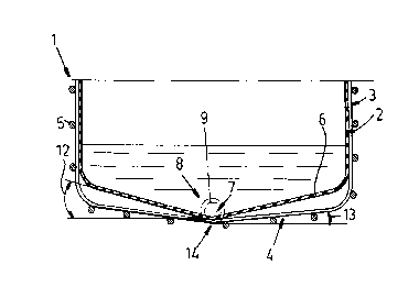
Figs. 4 and 5 are vertical sections through the con-
tainer embodying this invention at the start and ena of an
emptying operation, respectively; and
Fig. 6 is a vertical section through another embodiment
of this invention when empty.
Specific Description
As seen in Figs. 1 and 2 a transport/storage container
embodying this invention basically comprises a stiff outer
vessel 1 and an elastic liner 2 made of a thermoplastic synthetic
resin. The vessel 1 has a side part 3 formed of horizontal and
vertical rods 5 that are connected together in a gridwork and
welded together at their crossings and a floor 4 that can be
similarly constructed or made of wood like a pallet. The liner 2
has a side wall 15 and floor 6 of a shape identical except as de-
scribed below to that of the vessel 1 and is provided at the
juncture between its side wall and floor with an emptying fitting
or drain 8 having a valve or plug 9. The bars 5 are bent at the
corners to form the floor 4 in the illustrated arrangement.
As shown in Figs. 2, 4, and
4

~o~o~so
the floor 4 of the vessel 1 has a lowermost point 10 defined
by a Y-shaped trough 14 whose arms terminate at adjacent corners
of the floor 4 and whose leg ends in the middle of the side
between the two other corners. It is also possible as shown in
Fig. 3 for the floor 4 to have a single central trough 11.
Finally as shown in Fig. 6, it is even possible for the vessel 1
to have a planar floor 16.
In any case when the liner 2 is filled with a liquid as
shown in Fig. 4 the floor 6 of the liner 2 corresponds exactly to
l0 the shape of the floor 4 of the vessel 1 as the weight of the
liquid deforms the liner 2 to this shape. When, however, the
liner 2 is only partially full as shown in Fig. 5 or 6 the
natural elasticity of the liner 2 deforms it so that its floor 6
raises up to both sides of the low point 15, forming with the
horizontal an angle 12 of about 14° which is much more than the
angle 13 of about 6° that the rigid floor 4 forms with the
horizontal or the angle of 0° of Fig. 6.
As a result of this inherent elastic deformation the
liner 2 will drain much more rapidly than it would if it remained
20 of the same shape as the vessel floor 4. Nonetheless when the
container 1, 2 is filled it will be no higher than a standard
prior-art container of the same capacity.

Representative Drawing
A single figure which represents the drawing illustrating the invention.
Administrative Status

2024-08-01:As part of the Next Generation Patents (NGP) transition, the Canadian Patents Database (CPD) now contains a more detailed Event History, which replicates the Event Log of our new back-office solution.

Please note that "Inactive:" events refers to events no longer in use in our new back-office solution.

For a clearer understanding of the status of the application/patent presented on this page, the site Disclaimer , as well as the definitions for Patent , Event History , Maintenance Fee  and Payment History  should be consulted.

Event History

Description Date
Inactive: IPC from MCD 2006-03-11
Time Limit for Reversal Expired 2003-02-17
Letter Sent 2002-02-15
Grant by Issuance 2000-01-25
Inactive: Cover page published 2000-01-24
Inactive: Final fee received 1999-10-22
Pre-grant 1999-10-22
Letter Sent 1999-07-15
Notice of Allowance is Issued 1999-07-15
Inactive: Status info is complete as of Log entry date 1999-07-13
Inactive: Application prosecuted on TS as of Log entry date 1999-07-13
Inactive: Approved for allowance (AFA) 1999-06-17
Request for Examination Requirements Determined Compliant 1997-01-28
All Requirements for Examination Determined Compliant 1997-01-28
Application Published (Open to Public Inspection) 1990-08-25

Abandonment History

There is no abandonment history.

Maintenance Fee

The last payment was received on 1999-02-05

Note : If the full payment has not been received on or before the date indicated, a further fee may be required which may be one of the following

  • the reinstatement fee;
  • the late payment fee; or
  • additional fee to reverse deemed expiry.

Please refer to the CIPO Patent Fees web page to see all current fee amounts.

Fee History

Fee Type Anniversary Year Due Date Paid Date
MF (application, 8th anniv.) - standard 08 1998-02-16 1998-01-27
MF (application, 9th anniv.) - standard 09 1999-02-15 1999-02-05
Final fee - standard 1999-10-22
MF (patent, 10th anniv.) - standard 2000-02-15 2000-01-26
MF (patent, 11th anniv.) - standard 2001-02-15 2001-01-22
Owners on Record

Note: Records showing the ownership history in alphabetical order.

Current Owners on Record
SOTRALENTZ S.A.
Past Owners on Record
GEORGES ROSER
Past Owners that do not appear in the "Owners on Record" listing will appear in other documentation within the application.
Documents

To view selected files, please enter reCAPTCHA code :


To view images, click a link in the Document Description column. To download the documents, select one or more checkboxes in the first column and then click the "Download Selected in PDF format (Zip Archive)" or the "Download Selected as Single PDF" button.

List of published and non-published patent-specific documents on the CPD .

If you have any difficulty accessing content, you can call the Client Service Centre at 1-866-997-1936 or send them an e-mail at CIPO Client Service Centre.


Document
Description 
Date
(yyyy-mm-dd) 
Number of pages   Size of Image (KB) 
Representative drawing 2000-01-17 1 7
Cover Page 2000-01-17 1 34
Description 1994-04-01 6 185
Claims 1994-04-01 2 52
Cover Page 1994-04-01 1 12
Drawings 1994-04-01 3 71
Abstract 1994-04-01 1 18
Claims 1999-06-23 1 44
Description 1999-06-23 6 217
Commissioner's Notice - Application Found Allowable 1999-07-15 1 165
Maintenance Fee Notice 2002-03-18 1 179
Correspondence 1999-10-22 1 28
Fees 1997-01-21 1 53
Fees 1996-02-07 1 68
Fees 1995-02-02 1 43
Fees 1994-02-03 1 42
Fees 1993-01-27 1 50
Fees 1992-02-05 1 37
Correspondence 1994-04-28 1 18
Correspondence 1994-03-21 1 26
Courtesy - Office Letter 1990-10-22 1 58
Prosecution correspondence 1997-01-28 1 29
Prosecution correspondence 1999-05-05 3 109
Examiner Requisition 1998-11-05 2 45
Prosecution correspondence 1997-07-02 3 77