Note: Descriptions are shown in the official language in which they were submitted.
- 1 - 2o1o5so
PNEUMATIC TYRE
13AGKGROUND OF THE INVENTION
The present invention relates to a pneumatic
tyre, and more particularly to a heavy duty pneumatic tyre
having an inner liner capable of satisfactorily shutting
off from air and moisture, which is free from a crack gen-
eration problem due to high internal air pressure and due
to heat generated while the tyre is running.
Hitherto, a pneumatic tyre having a carcass and
an inner liner located radially inside of the carcass is
used especially for heavy duty use. The carcass has car-
cass cords and as the carcass cords normally steel cords
are used because of their high strength. However, if air
and moisture come into contact with the carcass cords made
of steel cords, the cords are corroded because of the pre-
sence of the air and moisture, and consequently the cords
are likely to be broken and the adhesion between the cords
and surrounding rubber material of the carcass is apt to be
destroyed. Thus, as a main component of the inner liner
material, butyl rubber is employed because of its high im-
permeability against air and moisture.
With respect to a rubber composition for a
tread, the carcass and suchlike portions, a rubber compo-
sition containing natural rubber is preferably employed in
order to reduce the heat generation in heavy duty use. In
connection with this material selection, halogenated butyl
rubber is widely used in the inner liner butyl rubber com-
position in consideration of better co-vulcanization (de-
gree of similarity in respective optimum vulcanizing con-
ditions such as temperature and duration time) between the
carcass comprising the rubber composition containing nat-
ural rubber and the inner liner comprising butyl rubber.
However, the inner liner made solely of halo-
genated butyl rubber is likely to become hard under
- 2 - 20 105 80
the influences of oxygen in the air and heat generated in
the running tyre, and this in combination with the bending
stress in the running tyre frequently results in a crack in
the inner liner. The crack, if it grows to reach the cen-
ter portion of the carcass, allows air and moisture to
enter, and therefore, there is a fear of corrosion of the
carcass cords, and consequently as previously mentioned,
the corrosion gives rise to the carcass cord breakage or a
separation problem due to the adhesion destruction between
the carcass cords and the surrounding rubber material.
An object of the present invention considering
the problem in the prior art is to provide a heavy duty
pneumatic tyre which is free from a crack generation pro-
blem due to thermal hardening even if the tyre heats up to
a high temperature while it is running, and furthermore,
highly impermeable against air and moisture and conse-
quently capable of preventing the carcass cord corrosion
from occurring. The present invention to attain the
aforementioned object was made based on the fining by the
inventors that a tyre satisfying every required character-
istics mentioned above can be obtained by employing a
specific inner liner made of butyl rubber wherein halo-
genated butyl rubber and ordinary (non-halogenated) butyl
rubber are mixed in a particular proportion.
SUMMARY OF THE INVENTION
In accordance with the present invention, there
is provided a pneumatic tyre having at least one layer of
carcass having one end and another end engaged with a pair
of bead cors on both sides with each of the ends being
tuned up outwardly from inner side around each of the pair
of bead cores, and an inner liner made of rubber compo-
sition located radially inside of the carcass, charac-
terized in that rubber component in the inner liner rub-
ber composition consists essentially of butyl rubber con-
taining halogenated butyl rubber in the range of 60 to
- 3 _ 2010580
95 % by weight (hereinafter, % means % by weight unless
otherwise specified).
Halogenated butyl rubber includes halogen as a
component element, and therefore, tends to be readily
hardened by heating to a high temperature. This tendency
is more conspicuously observed in halogenated butyl
rubber having higher halogen content.
The halogen content in one molecule is
preferably 5.0 % or less, more preferably 3.0 % or less,
still more preferably 2.5 % or less in consideration of
minimizing of the aforementioned thermal hardening at
high temperature in a heated up condition. Additionally,
on the basis of another consideration concerning better
co-vulcanization with the rubber composition in the
carcass, the halogen content is preferably 0.5 % or
higher, more preferably 1.0 % or higher.
Examples of the aforementioned halogenated
butyl rubber are, for instance, chlorinated butyl rubber,
brominated butyl rubber and the like. Among those,
brominated butyl rubber is particularly suitable because
brominated butyl rubber gives better co-vulcanization
with the rubber composition in the carcass.
The halogenated butyl rubber can be obtained by
halogenation of ordinary butyl rubber usually used for an
automobile tyre (hereinafter refered to as "regular butyl
rubber"). The regular butyl rubber is isobutylene-
isoprene copolymer normally having isoprene content, i.e.
degree of unsaturation of the copolymer, in the range of
about 0.6 to about 4.2 mole %.
Non-halogenated butyl rubber used together with
the halogenated butyl rubber can be the aforementioned
regular butyl rubber.
The inner liner rubber composition in
accordance with the present invention is prepared so that
rubber component thereof contains 60 to 95 %, preferably
70 to 90 %, of halogenated butyl rubber and 5 to 40 %,
preferably 10 to 30 %, of the regular butyl rubber.
An inner liner rubber composition with the
_ 4 _ ~0 1 05 80
halogenated butyl rubber content in the rubber component
of less than 60 % has a tendency to exhibit insufficient
characteristics with respect to co-vulcanization with the
carcass rubber composition which results in a fear of
separation problem of the inner liner from the carcass.
On the contrary, an inner liner rubber composition with
the halogenated butyl rubber content in the rubber
component of more than 95 % has a tendency to allow an
outbreak of the crack problem.
The inner liner rubber composition can be
obtained through a process wherein a rubber component
consisting essentially of specified respective amounts of
the halogenated butyl rubber and the regular butyl rubber
is subjected to heating and mixing so as to become the
particular rubber composition and the composition is
shaped into desired form. The rubber composition may
include other ingredients which are normally included in
a conventional rubber composition. Examples of the
aforementioned other ingredients are: an ingredient for
improving reinforcement of the rubber, e.g. carbon black;
an ingredient serving as vulcanizing assistant and
improving workability, e.g. process oil; an ingredient
acting on butyl rubber as vulcanization-retarder and
preventing scorching, e.g. magnesium oxide,
mercaptobenzothiazyl disulfide (hereinafter referred to
as MBTS); a vulcanization-accelerator, e.g. zinc flower;
a vulcanizing agent, e.g. sulfur; and the like.
Next, there is provided an explanation of a
pneumatic tyre of the present invention referring to the
accompanying drawing.
BRIEF EXPLANATION OF THE DRAWING
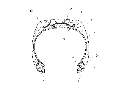
Fig. 1 is a cross sectional view of a pneumatic
tyre of the present invention along its width.
DETAILED DESCRIPTION
Fig. 1 is a cross sectional view along width
showing a pneumatic tyre of 11R 24.5 size in accordance
2010580
- 5 -
with the present invention.
A tyre 10 has a tread portion 3, side wall por-
tions 6 extending from both ends of the tread portion 3
toward respective sides of the tyre, and bead portions 5
located respectively at radially inside ends of both side
wall portions 6. Both ends of a carcass 2 are turned up
outwardly from axially inner side respectively around a
pair of bead cores 1 respectively on the right hand side
and on the left hand side so as to be engaged with the bead
cores 1 in the bead portions 5. In the illustrated embodi-
ment, the carcass 2 comprises one layer of parallel steel
cords laid in good order at an angle of about 90 degrees
relative to the peripheral (hoop) direction. However the
carcass may comprise two or more layers as occasion de-
mands.
In addition, a reinforcing layer 8 is provided
on axially outside of the carcass cord turning up portion,
and a bead apex 9 is located on radially outside adjacent
to the bead core 1.
Further, a belt layer 4 comprising steel cords
is located at a place which is on radially inside of the
tread 3 and which is also on radially outside of the car-
cass 2. The belt layer 4 comprises a plurality of cord
layers with cord directions intersecting at a relatively
small angle.
The pneumatic tyre 10 has an inner liner 7 on
radially inside adjacent to the carcass 2, and as mentioned
previously, the inner liner 7 is made of; a rubber composi-
tion containing the halogenated butyl rubber of 60 to 95%
and the regular butyl rubber of 5 to 400; and other ingred-
ients added as occasion demands.
Hereinafter, the pneumatic tyre of the present
invention is further explained based on several embodi-
ments, although the present invention is not limited to
these embodiments.
Examples 1 to 5 and ComBarative Examples 1 to 2
In accordance with the mixing proportion shown
2010580
- 6 -
in Table-1, halogenated butyl rubber (Bromobutyl 2255
(halogen content: 2 %); available from Exxon chemical
Japan, Ltd., trade name), non-halogenated butyl
rubber(Butyl 265; available from Exxon Chemical Japan
Ltd., trade name), carbon black (Niteron 55S; available
form Shin-Nittetsu Kagaku Kabushiki Kaisha, trade name),
process oil, stearic acid, magnesium oxide and MHTS were
mixed and kneaded. Then, after zinc flower and sulfur
were added, the mixture was furhter mixed and kneaded,
and subsequently test pieces (55mm-long, 55mm-wide, 4mm-
thick) were prepared.
For the purpose of property measurement of the
obtained test pieces, (a) scorching time TL+2, (b) 90
vulcanizing time and (c) maximum torque were measured
through rheometer test, and further after-vulcanization-
properties (hardness and De mattia Cut Growth) and
adhesive property with the carcass were also
investigated. These measurements were conducted in the
following manner. The measurement results are also shown
in Table-1.
Values of scorching time TL+2, 90 % vulcanizing
time and maximum torque in rheometer test were measured
at measurement temperature of 150°C with a rheometer 8-
100 (available from Monsant Japan Ltd., trade name) being
used.
De mattia Cut Growth as one of the after-
vulcanization-properties was measured in a manner wherein
a 2mm-wide crack at surface strain of 60 % was prepared
on a test piece and the test piece was subjected to
benidng with De mattia fatigue test apparatus used, so
that the number of times of bending required for the
crack width growth by lmm was investigated respectively
both in the normal (new) condition and in the aged
condition in which a test piece had been aged through
heating for 150 hours at a temperature of 110°C.
The adhesive property with the carcass was
tested in a manner wherein a rubber composition for
adhering steel cords was adhered to a test piece and the
- ~ - 20 1 05 80
test piece with the rubber composition was subjected to
pressing and valcanizing for 6 minutes at a pressure of
30 kg/cm2 and a temperature of 150°C, and thereafter the
adhesive property was determined based on a procedure of
JIS (Japanese Industrial Standard) K 6301.
~a i.~~v
_8_
H
Lf1tl~L1~Lf1Lf1 ~f1 tn I
'b
-I O O O O O O O
C
rl
W
H
Q
U 3 U
Q M M M M M M M I
r1 rl
N W
r~r~ r~rlr~ r~ rl
1~
rl
N
U U
U G ~ O O O O O O O
3
x
a o
u7 U
.i
H H
(a ~ N N N N N N N
Ar v .-1
.-- ~ U
N
N
C N
U N
G 4J
O U O O O O O O O
U O rl r-Irl r-1rlr-1 r-I r-I
H ..r
,L7 O ~ O
U
C
O
.Q U
ra cp O O O O O O O
(~ rl ~D~O ~O~D~O ~D ~O
U ~2
H
v
.d
H
U H H
p cW n O o o mn o
~ r-I M M N r-I d'
r-1
1.-i (J1
1~
4J
~
r~ 1-r
.~
W
H
y.y f1 O O O Il1 Lf1 O
U ~O I~ 00G1 01 Lf1 O
O ~,
Qj r-IN M d' Ill r-I N
C1 ~ O k ~C >C~C >C O >C O ~C
En C, 2 W W W W W U W U W
2010580
to U1U ~c1 ~r7 O O O
U ~ \ . . . . . O O
N f3.~.~ U w 0 ~ co co co
p n co
co a 3 U ~-
s~ ~c ~c ~ o o ~c o
0 0 0 .- m o
a .n ~a ~ ~ ~ x x rl x
v E a~ x x x M c~ x N
c~ rl ~ ~c
((fC (0 ~ ~ N r- W --I O
rW .
1~ 4J 4J U
l~ .CE ~O t0 m0 l0 ~D ~O ~O
t- s.)
C~ 1~.i O O O O O O O
O O
E 3 .~ 3 ~-I ~--I~ ~ ~I ~-I ~I
~ ~
o a~ x x x x x x x
a~ N w a o o o M m o m
w s.~
A C7O d' ~' C' N rl d
O O
N U7
U CJ N
V .-1 'DO S..iN Lf1 00 N C' 01 ~O
U ~ ~ ~n a m ~n u, ~ ~ c vc
N a~~ o
w v m
a
o
_
N s..a U7
U , ri N
[-i I h ''t~O S ml C' ~D O N 01 M
1 Q O a Lf1 t,f1tI1 v0 vD C' ~O
W C ~ ~ O
p ri U1 ~
N U1
U1 .
U C C ,
.1 rQ rp N
U s...'D t-~~ N ~!1 co o~ a0 rI
co v O a m n um c, ~r, c vc
v a x ~ ~n o
as
o I
w
C4 ~ 3
1J QJ O rl M ~O f~ 00 CO
't7 W C lf7 ~!1 ~! W un C' X11
La
C
N
(Q I
4J E m ~
a v w N
a C ~ C' N Lfl M N C r1
.,i~ C ~
x >..o v ~r a ~c ao c~ M o
lp O ) C N N N N N N M
1~ ~ JJ
N
Ql
w I
ri Q1 N
N a C 4J
41 ,7 'i 17 O ll7 M r-II Wf1 Lf1
y N C
4J oW ~ OJ F'..l0 O O O r-I CO t0
C ,~"-1 N N r~ O C1 M 00
O O (1J~'~~ rl rl ri r-i r-I
~ U .rJ
C N
-.a G1
,C ~J tl1 it1 ~-I ~D M O O
I U a
N 4JC I WO tI1 ~r V' Q1 ~1
Q7 O E w1
a U w-E
C N .i.~--
yl Q rl N M d' Ln rl N
U U v O X ~C X ~C >C O 7C O
>C
I r1a~ z w w w w w v w v
w
- to -
The results shown in Table-1 demonstrate that
the test piece of Comparative Example 1 having higher
regular butyl rubber content in butyl rubber than the
test pieces prepared in accordance with the present
invention gives far lower adhesive property with the
carcass than the test pieces of Examples 1 to 5, although
Comparative Example 1 exhibits only a small change due to
aging, and that on the other hand the test piece of
Comparative Example 2 containing no regular butyl rubber
in butyl rubber exhibits a sharp change due to aging,
although Comparative Example 2 gives enough adhesive
property with the carcass.
Example 6 and Comparative Example 3
A pneumatic tyre of Example 6 of 11R 24.5 size
having a construction shown in Fig. 1 was prepared in
which the same rubber composition as Example 3 was
applied to the inner liner.
Another pneumatic tyre of Comparative Example 3
of the same size and the same construction as Example 6
was prepared in which the same rubber composition as
Comparative Example 2 was applied to the inner liner.
These tyres were subjected to the running test
for 600 hours at internal air pressure of 8.0 kg/cm2,
load of 6200 kg and speed of 20 km/hour, so that the
change in the inner liner hardness between before and
after the running were determined. The results are shown
in Table-2.
In addition, a crack having a depth of lmm and
a length of lmm had been prepared on the buttress portion
of each tyre prior to the running, so that each carck
growth (mm) was measured after the aforementioned running
of the tyre under the described condition. The results
are also shown in Table-2.
- m - 20 1 05 80
3
O
i., .. m
C7 E
E o .-i
U
a
U
c~ C
.,i
U7 C
H C
N l0 I~
in ~O
N 4
U1 al
N 1J
C w
z7 m
c0
x
C
...,
c C
a
i.a M Cn
v
C tr
C O
H W
.n
N
k
4. M W
QJ
C
k O
~l W U
m
.'.,
s.~ W 1 U7
s
4J r0 c0
4J
C
+~
C CJ U
cQ
H E E
~
N U1
c~
k
o w
z
x x O
W W U
- 12 - 20 1 05 80
The results shown in Table-2 demonstrate that
even if the tyre of Example 6 has a crack on its buttress
portion the crack does not grow, and therefore that the
tyre of Example 6 is suitable for practical use.
Thus, the pneumatic tyre of the present
invention is free from a crack generation problem due to
thermal hardening even if the tyre heats up to a high
temperature while it is running, and furthermore, the
pneumatic tyre of the present invention is highly
impermeable against air and moisture and consequently
prevents a carcass cord corrosion problem from
occurring. Therefore the pneumatic tyre of the present
invention can be suitably used as a tyre of, for example,
heavy cargo truck.