Language selection

Search

Patent 2010740 Summary

Third-party information liability

Some of the information on this Web page has been provided by external sources. The Government of Canada is not responsible for the accuracy, reliability or currency of the information supplied by external sources. Users wishing to rely upon this information should consult directly with the source of the information. Content provided by external sources is not subject to official languages, privacy and accessibility requirements.

Claims and Abstract availability

Any discrepancies in the text and image of the Claims and Abstract are due to differing posting times. Text of the Claims and Abstract are posted:

  • At the time the application is open to public inspection;
  • At the time of issue of the patent (grant).
(12) Patent: (11) CA 2010740
(54) English Title: POST BEAM LOCK CONNECTION
(54) French Title: CONNEXION A VERROUILLAGE POUTRE-POTEAU
Status: Term Expired - Post Grant Beyond Limit
Bibliographic Data
Abstracts

English Abstract


A B S T R A C T
A connection for securing a horizontal structural member to
a vertical structural member includes a first plate dimensioned
for attachment to the end of a horizontal member. The first
plate has an inner face apertured to accept a bolt extending
into the horizontal member, and at least one outer face apertured
to accept a bolt extending through the vertical member. The
inner and outer faces are spaced from one another sufficiently
to permit bolt heads to be contained between the members. A
second plate is provided for emplacement on the vertical member
opposite the first plate, second plate being apertured to accept
the bolts extending through the vertical member from the outer
face of first plate. Bolts and bolt securing means connect the
first and second plates together on opposite sides of a vertical
member. A bolt extends into the horizontal member to connect the
first plate thereto.


Claims

Note: Claims are shown in the official language in which they were submitted.

THE EMBODIMENTS OF THE INVENTION IN WHICH AN EXCLUSIVE PROPERTY
PRIVILEGE IS CLAIMED ARE DEFINED AS FOLLOWS:
1. A connection for securing a horizontal structural member to
a vertical structural member including:
(a) a first plate dimensioned for attachment to the end of
a said horizontal member, said first plate having an
inner face apertured to accept a bolt extending into
said horizontal member, and at least one outer face
apertured to accept a bolt extending through said
vertical member, said inner and outer faces being
spaced from one another sufficiently to permit bolt
heads to be contained between said members;
(b) a second plate for emplacement on said vertical member
opposite said first plate, said second plate being
apertured to accept said bolts extending through said
vertical member from said outer face of said first
plate;
(c) bolts and bolt securing means for connecting said first
and second plates together on opposite sides of a
vertical member;
(d) a bolt for extending into said horizontal member to
connect said first plate thereto.

2. A device as described in Claim 1, wherein said first and
second plates are identical, whereby a pair of aligned horizontal
members may be connected to a vertical member.
3. A device as described in Claim 1 or 2, wherein said first
plate includes two said outer faces one above and one below said
inner face.
4. A device as described in Claim 3, wherein said first plate
is provided with a flange below the lower of said outer faces,
extending beneath a said horizontal, member, said flange being
apertured to accept a screw to secure said first plate to a said
horizontal member.
5. A device as described in Claim 4, wherein said first plate
is provided with an upper flange above the upper of said outer
faces, said upper flange being apertured to accept a screw to
further secure said first plate to a horizontal member.
6. A device as described in Claim 4 or 5, further including
a threaded member for lateral insertion into a said horizontal
member, to cooperate with the bolt extending into same from said
inner face of said first plate.

Description

Note: Descriptions are shown in the official language in which they were submitted.


ZC1~0741~
The present invention relates to the field of construction
hardware, and provides an improved post beam connection.
It is generally the practice, when mounting a beam or joist
to a post for vertical support thereof, to utilize either a joist
hanger or to nail the beam to the top surface of the post.
Alternatively, a joint may be cut in the post and the beam inserted
therein. Specially made joints, however, require a great deal of
skilled labour to execute properly, and do not provide a structure
which can be easily disassembled if desired. Similarly, other
known methods of post-beam connection are designed for permanent
structures.
The object of the present invention is to provide a reliable
means of post-beam connection which can be quickly assembled by
relatively unskilled labour, and similarly disassembled easily.
The present invention is intended for use in situations where a
permanent, or solid but temporary structure, is required. The
present invention is designed for assembly by non-specialized
labour. Examples of proposed applications of the present invention
are for prefabricated and modular structures, such as those
utilized in construction in remote areas where one might desire to
build an oil and gas exploration camp or a military installations.
In drawings which illustrate the present invention by way
of example:
~4

: Z~7~0
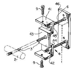
Figure 1 is a perspective view of an embodiment of the
present invention for joining one vertical to one horizontal
structural member;
Figure 2 is a perspective view of an embodiment for joining
two horizontal to one vertical structural member;
Figure 3 is a perspective view of an embodiment of the
present invention for joining four horizontal to one vertical
structural member.
Referring first to Figure 1, the present invention provides
a profiled shoe or hanger 4 which is dimensioned to fit onto the
end of a horizontal beam or joist. This shoe is provided with
upper and lower flanges 41,42 which engage the top and bottom
surfaces of a beam or other horizontal structural member.
The shoe is provided with an inner face 43 which abuts the
end of the horizontal structural member. Above and below this
face are outer faces 45 and 44 which present a flat outer surface
to abut a vertical structural member. Each of the faces 43, 44,
45, is apertured to accept bolts. It will be observed, also,
that the inner and outer faces are offset from one another. In
this way, there is a sufficient space between the inner face 43
and a vertical member to accommodate the head of a bolt 3.
Similarly, this offsetting permits a sufficient space between the
outer faces 44,45 and a horizontal member to accommodate the head
of a bolt 6.
f~

`--
2~
To utilize the present invention, one first drills a pair
of holes at right angles into a horizontal structural member.
The first of these is drilled inwardly from the end of the
member, to accommodate a bolt 3 which is passed through the
aperture in the inner face of the shoe. The second is drilled
at right angles to the first, right through it, and is
dimensioned to accommodate a cylindrical nut which is inserted
therein. This nut is provided with a threaded aperture to
threadingly engage bolt 3. A lock washer will be provided
between the head of bolt 3 and the shoes, so retightening will
not have to be carried out. The shoe is then installed on a
vertical member at the point where one wishes to install a
horizontal member. If one wishes to attach a horizontal to a
vertical member at, for instance, a corner, and one does not wish
to attach a further horizontal member to the vertical in a
straight line, then a plate is placed on the opposite side of the
vertical member. Plate 46 is apertured at points aligning with
the apertures in the outer faces 44,45 of the shoe. Bolts 6 are
then inserted through the plate, through pre-drilled holes in the
vertical member, and through the aligned apertures in the outer
faces. The bolts engage nuts which are inserted into the spaces
between the shoe and the horizontal members, and the bolts are
then tightened. Preferably, lock nuts are used, so no re-
tightening is required. The horizontal member is then fitted
onto the shoe which is attached to the vertical member, and
screws 9 used to attach the flanges to the top and bottom
surfaces of the member. Cylindrical nut 2 is inserted into the

7a~0
member, and bolt 3 is passed through face 43 and the horizontal
member, and tightened into the nut 2. Bolt 3 ought to be of a
strong structural grade. The shoe is now secured to the
horizontal member. Additional shoes are secured to additional
horizontal members, as required.
If two horizontal members are to be mounted in a straight
line, then the bolts 6 will be utilized to attach two shoes in
a line with each other on a vertical member and then horizontal
members will be mounted onto same, as described above.
In order to utilize the present invention to attach three
or four horizontal members to a vertical member, one proceeds as
above, depending on whether the horizontal member being
installed will or will not be aligned with another horizontal
member.
''
Furthermore, it will be noted that in order to permit
horizontal members to be installed at right angles to one
another, pairs of vertically aligned apertures are provided in
outer faces 44,45 and plate 46. Accordingly, it will be seen
that the bolts 6 connecting together two pairs of horizontal
member at right angles will pass over one another.
Generally speaking, then, it will be understood that the
sequence followed in any utilization of the present invention
will be as follows:

2~0~74~
Step 1: The shoes and plates are installed first to any
vertical member, with the bolt 3 already in place;
Step 2: The pre-drilled end of the horizontal member is
put into place by sliding the bolt 3 into the
horizontal member and into the cylindrical nut 2
which is positioned in the pre-drilled hole in
the horizontal member;
Step 3: By turning the bolt 3 between inner face 43 and
the vertical member with the help of a wrench, the
horizontal member is pulled towards the vertical
member and locked into the shoe; and
Step 4: Finally, the horizontal member is secured with the
screws 9 through the top and bottom flange 41,42.
It is to be understood that the examples described above are
not meant to limit the scope of the present invention. It is
expected that numerous variants will be obvious to the person
skilled in the building hardware design art, without any
departure from the spirit of the present invention. The appended
claims, properly construed, form the only limitation upon the
scope of the present invention.
;~ .

Representative Drawing
A single figure which represents the drawing illustrating the invention.
Administrative Status

2024-08-01:As part of the Next Generation Patents (NGP) transition, the Canadian Patents Database (CPD) now contains a more detailed Event History, which replicates the Event Log of our new back-office solution.

Please note that "Inactive:" events refers to events no longer in use in our new back-office solution.

For a clearer understanding of the status of the application/patent presented on this page, the site Disclaimer , as well as the definitions for Patent , Event History , Maintenance Fee  and Payment History  should be consulted.

Event History

Description Date
Inactive: Expired (new Act pat) 2010-02-22
Inactive: Entity size changed 2007-02-16
Inactive: IPC from MCD 2006-03-11
Inactive: Entity size changed 2002-02-13
Grant by Issuance 1994-05-10
Application Published (Open to Public Inspection) 1991-08-22
Request for Examination Requirements Determined Compliant 1990-06-26
All Requirements for Examination Determined Compliant 1990-06-26
Small Entity Declaration Determined Compliant 1990-02-22

Abandonment History

There is no abandonment history.

Fee History

Fee Type Anniversary Year Due Date Paid Date
MF (patent, 8th anniv.) - small 1998-02-23 1998-02-04
MF (patent, 9th anniv.) - small 1999-02-22 1999-02-03
MF (patent, 10th anniv.) - small 2000-02-22 2000-01-21
MF (patent, 11th anniv.) - small 2001-02-22 2001-02-09
MF (patent, 12th anniv.) - standard 2002-02-22 2002-02-06
MF (patent, 13th anniv.) - standard 2003-02-24 2003-02-19
MF (patent, 14th anniv.) - standard 2004-02-23 2004-02-16
MF (patent, 15th anniv.) - standard 2005-02-22 2005-02-09
MF (patent, 16th anniv.) - standard 2006-02-22 2006-02-16
MF (patent, 17th anniv.) - small 2007-02-22 2007-02-16
MF (patent, 18th anniv.) - small 2008-02-22 2008-02-07
MF (patent, 19th anniv.) - small 2009-02-23 2009-02-18
Owners on Record

Note: Records showing the ownership history in alphabetical order.

Current Owners on Record
WOLF WILBERT
Past Owners on Record
None
Past Owners that do not appear in the "Owners on Record" listing will appear in other documentation within the application.
Documents

To view selected files, please enter reCAPTCHA code :


To view images, click a link in the Document Description column. To download the documents, select one or more checkboxes in the first column and then click the "Download Selected in PDF format (Zip Archive)" or the "Download Selected as Single PDF" button.

List of published and non-published patent-specific documents on the CPD .

If you have any difficulty accessing content, you can call the Client Service Centre at 1-866-997-1936 or send them an e-mail at CIPO Client Service Centre.


Document
Description 
Date
(yyyy-mm-dd) 
Number of pages   Size of Image (KB) 
Abstract 1994-07-08 1 21
Claims 1994-07-08 2 49
Drawings 1994-07-08 3 60
Description 1994-07-08 5 146
Representative drawing 1999-07-08 1 11
Fees 2003-02-18 1 37
Fees 2002-02-05 1 36
Fees 2000-01-20 1 36
Fees 1998-02-03 1 44
Fees 1999-02-02 1 42
Fees 2001-02-08 1 32
Fees 2004-02-15 1 38
Fees 2005-02-08 1 34
Fees 2006-02-15 1 35
Fees 2007-02-15 1 59
Correspondence 2007-02-15 1 16
Fees 2008-02-06 1 64
Fees 2009-02-17 1 61
Fees 1997-02-12 1 41
Fees 1995-01-22 1 35
Fees 1996-01-22 1 37
Fees 1994-02-07 1 31
Fees 1993-01-21 1 24
Fees 1991-12-08 1 26
Prosecution correspondence 1990-06-11 1 30
Prosecution correspondence 1990-06-25 1 36
Courtesy - Office Letter 1990-09-30 1 19
Courtesy - Office Letter 1990-12-04 1 38
PCT Correspondence 1990-11-28 1 33
Prosecution correspondence 1994-02-20 1 40
PCT Correspondence 1994-02-20 2 47
Prosecution correspondence 1992-11-19 2 46
Examiner Requisition 1992-05-28 1 69