Language selection

Search

Patent 2010962 Summary

Third-party information liability

Some of the information on this Web page has been provided by external sources. The Government of Canada is not responsible for the accuracy, reliability or currency of the information supplied by external sources. Users wishing to rely upon this information should consult directly with the source of the information. Content provided by external sources is not subject to official languages, privacy and accessibility requirements.

Claims and Abstract availability

Any discrepancies in the text and image of the Claims and Abstract are due to differing posting times. Text of the Claims and Abstract are posted:

  • At the time the application is open to public inspection;
  • At the time of issue of the patent (grant).
(12) Patent Application: (11) CA 2010962
(54) English Title: UNITARY PUSH-PULL FORCE TRANSDUCER
(54) French Title: TRANSDUCTEUR DE FORCE SYMETRIQUE MONOBLOC
Status: Deemed Abandoned and Beyond the Period of Reinstatement - Pending Response to Notice of Disregarded Communication
Bibliographic Data
(51) International Patent Classification (IPC):
  • G01L 1/08 (2006.01)
  • G01L 1/16 (2006.01)
  • G01L 1/18 (2006.01)
  • G01P 15/08 (2006.01)
  • G01P 15/097 (2006.01)
  • G01P 15/10 (2006.01)
  • G01P 15/12 (2006.01)
(72) Inventors :
  • NORLING, BRIAN L. (United States of America)
(73) Owners :
  • SUNDSTRAND DATA CONTROL, INC.
(71) Applicants :
  • SUNDSTRAND DATA CONTROL, INC. (United States of America)
(74) Agent: RICHES, MCKENZIE & HERBERT LLP
(74) Associate agent:
(45) Issued:
(22) Filed Date: 1990-02-27
(41) Open to Public Inspection: 1990-08-27
Examination requested: 1990-02-27
Availability of licence: N/A
Dedicated to the Public: N/A
(25) Language of filing: English

Patent Cooperation Treaty (PCT): No

(30) Application Priority Data:
Application No. Country/Territory Date
316,341 (United States of America) 1989-02-27

Abstracts

English Abstract


UNITARY PUSH-PULL FORCE TRANSDUCER
Abstract of the Invention
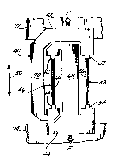
A push-pull force transducer comprising a unitary body (40) formed from a
crystalline substrate. The body comprises first and second mounting elements
(40, 42) for mounting the force transducer to first and second structures (72, 74),
and first and second force sensing elements (46, 48) connected to the mounting
elements. Each force sensing element has first and second ends, a line extendingfrom the second to the first end defining a force sensing axis for the force sensing
elements. The force sensing elements are oriented with their force sensing axes
parallel to and aligned with one another. The first force sensing element has its
first end connected to the second mounting element and its second end connected
to the first mounting element. The second force sensing element has its first end
connected to the first mounting element and its second end connected to the
second mounting element. Also described are embodiments utilizing strain relief
flexures and an embodiment featuring a leveraged design..


Claims

Note: Claims are shown in the official language in which they were submitted.

-7-
The embodiments of the invention in which an exclusive property or privilege
is claimed are defined as follows:
1. A force transducer capable of being attached between first and
second structures (72, 74, 90, 92, 130, 132), the force transducer comprising a
unitary body (40, 80, 108) formed from a crystalline substrate, the unitary bodycomprising:
first and second mounting elements (42, 44, 82, 84, 110, 112) for mounting
the force transducer to the first and second structures, respectively;
first and second force sensing elements (46, 48, 86, 88, 114, 118), each force
sensing element having first and second ends (62, 64, 52, 54), a line extending from
the second end to the first end of each force sensing element defining a force
sensing axis (26, 36) for the force sensing element, each force sensing element
being sensitive to a force exerted in either direction along its force sensing axis,
the force sensing elements being oriented with their force sensing axes parallel to
and aligned with one another; and
coupling means (68, 70, 100, 120, 122) for interconnecting the mounting
elements and force sensing elements such that the first force sensing element has
its first end connected to the second mounting element and its second end
connected to the first mounting element, and such that the second force sensing
element has its first end connected to the first mounting element and its secondend connected to the second mounting element, whereby a force exerted on the
force transducer by the structures parallel to the force sensing axes results in a
compression force on one force sensing element and a tension force on the other
force sensing element.
2. The force transducer of Claim 1, wherein the coupling means
comprises a bridge member (102, 120, 122) connected to the first end of one of the
force sensing elements and to the second end of the other force sensing element,and further connected to one of the mounting elements by flexure means (104,
126, 128), the flexure means permitting rotation of the bridge member with
respect to said one mounting elements around a strain relief axis normal to a plane
containing the force sensing axes.
3. The force transducer of Claim 1, wherein the coupling means
comprises first and second bridge members (126, 128), the first bridge member
being connected to the second end of the first force sensing element and to the

-8-
first end of the second force sensing element and further being connected to thefirst mounting element by first flexure means, the second bridge member being
connected to the first end of the first force sensing element and to the second end
of the second force sensing element, and further being connected to the second
mounting element by second flexure means, each flexure means permitting
rotation of the respective bridge member with respect to the respective mountingelement about a strain relief axis normal to a plane containing the force sensing
axes.
4. The force transducer of Claim 1, wherein the crystalline substrate
comprises crystalline quartz.
5. The force transducer of Claim 4, wherein each force sensing element
comprises a dual vibrating beam force transducer.
6. The force transducer of Claim 4, wherein the unitary body comprises
a tuning fork temperature sensor (140).
7. The force transducer of Claim 1, wherein the crystalline substrate
comprises silicon.
8. The force transducer of Claim 7, wherein each force sensing element
comprises a dual vibrating beam force sensing element.
9. The force transducer of Claim 1, wherein a portion of the coupling
means extends between the force sensing elements.
10. A force transducer capable of being attached between first and
second structures for measuring a force exerted on the force unitary body (150)
formed from a crystalline substrate, the unitary body comprising:
first and second mounting elements (152, 154) for mounting the force
transducer to the first and second structures, respectively;
first and second force sensing elements (156, 158), each force sensing
element having first and second ends, a line extending from the second end to the
first end of each force sensing element defining a force sensing axis for the force
sensing element, each force sensing element being sensitive to a force exerted in

-9-
either direction along its force sensing axis, the force sensing elements being
oriented with their force sensing axis parallel to and aligned with one another; and
coupling means for interconnecting the mounting elements and force sensing
elements, the coupling means comprising a first bridge member (162), first flexure
means (164) for connecting the first bridge member to the first mounting element,
and second and third flexure means (166, 168) for connecting the first bridge
member to the first ends of the first and second force sensing elements,
respectively, a second bridge member (172), fourth flexure means (174) for
connecting the second bridge member to the second mounting element, fifth and
sixth flexure means (176, 178) for connecting the second bridge member to the
second ends of the first and second force sensing elements, respectively, all
flexures permitting rotation of components to which they are attached about
strain relief axes normal to a plane containing the force sensing axes, the flexures
to which each bridge member is attached being spaced from one another along a
transverse direction in said plane and normal to the force sensing axes, the second
flexure being positioned between the first and third flexures along said transverse
direction, the fifth flexure being positioned between the fourth and sixth flexures
along said transverse direction, whereby a given force exerted on the mounting
elements by the first and second structures causes the first and second bridge
sections to pivot in opposite directions about the second and fifth flexures,
respectively, producing a compression force on one force sensing element and a
tension force on the other force sensing element.

Description

Note: Descriptions are shown in the official language in which they were submitted.


. i9~r~ 14:11 F~CIrl '~L~ STF~'h~ LEI~L. ~l~FT. r~ c4l?l~ rJl5~
f~ .
- 20~09~;~
UNl'rARY PVSH-PlJLL FORC~ TlRAN81)UCl~R
Field ot the In~entlon
The present invention rel~te3 to foroe transducer3 and, In partlcul~r, to
t~r¢e transdlloers that include two torca sensln~ elements arran~ed in 8 push-pull
contlguration.
~Ld~
A common method oS reduc~n~ errors In ~orce transducer systems 18 to uge a
push-pull ~rrangement ~n whlch two well matohed ~orce senslng elements ~re
contt~ured such that they ~re 3u~eoted to ~orces In opposlte dlrectlons. The
putpose o~ thls al~ngement 18 to cancel common mode errors, such ~s even order
nonlinearities, bias ternperature ~en~itl~lty, olook 6ens~tlvlty, blas Aglng drlft, snd
prefi~ure sen~ltlvlty.
Problerns ari~ when a ~ush-pull arrangement Is lmplementcd ln A physlcal
device. For example, to utll~ze push-pull ~orce sensin~ elements In ~ pendulous
accelerometer, two force sen~ln~ elements flre both oonnected to ~ common proo~
mss8. The ~orce sensln~ element8 typlc~lly extend either perpendleular to or
parallel to the pendulous ~x~s o~ the aceelerometer. Howcver in sueh a
confl~uratlon, any thermal expanslon mismstch between the support/proof mass
asseml)ly and the ~orce l~ensiil~! clement~ creates thermal strR;ns th~t in turn~0 erèate lergc common mode error slgnals that can only be psrtlslly sllppressed by
slgnal proeég~ng techniques. As a result"he force tensln~ clements should be
~- physically matched In all sen~ltivltlet, in oraier to provide a hlgh level o~ oommon
mode re~ect~on Thls clo6e mat¢hln~ 1~ often dlfflcult to achlevc.
Summary of the Invention
The present inventlon provldc~ a push-pull force transducer faorlcated as ~
un~tary structure. The tran~ducer may be connected, ror exsmple, ~etween the
proot mass and the sup~ort of an secelerometer, to provlde a sensor havlng
Improved relectlon ot common mode errors.

~9 ~ 8, 108~ FFl_il' S~ l)UTP~8~i LEG~L [~EFT. ~0 _ ~ 8~8~51:8~S:~1 F.81LS
2~1096~
In a first preferred embodlrnent the ~orce tr~nsducer compr~ses ~ unltary
body ~ormed from ~ cry~tall5ne s~lbstrate. The unlt~ry body comprises tlrst and
second mountlng e]ements tor moun~;in~ the force trsnsducer tv flrst and second
structures ~nd ~irst and second force sensin~ elements connected to the mountln~elements. E~ch ~orce senslng element has flrst and second ends A line extendlng
~rom the second end to the flrst end deflnlng ~ foroe sensing ~xis for the forcesensln~ element. Each torce senslng element ls sen~ltive to a force exerted ln
elther dlrectlon ~long Its ~orce ~ensln~ 8xls. The Port~e s¢nslng elements are
oriented wlth thelr force senslng axls pQrallel to ~nd ~llgned wtth one another.~oupllng means oonnect~ e~ch force sensing olement to both mountlng elements.
The first force senslng element has its fir~t end conne~tcd to the se~ond mountlng
ele nent and its second end connecll!d to the flrst mount)ng element. The ~econdrorce sensln~ element has it~ ~irsS end connected to the flrst mountlng element
~nd lls second end connected to the seoond mounting element. Thus n tor~e
exerted on the force tr8nsducer by these structures p~rallel to the ~orce senslng
axes result~ in a compresslon ~orce on one for¢e sensin~ element and a ten.~on
force on the other foroe sensln~ element. In further embodiments ~Iexures are
used to prov~de ~t~a)n relle~ wlthln the unlt~ry body and n portion ot the body 1
~ormed 80 as to produce a lever8gin~ efreot that re~ults in push-pull operat50n.Z0 Brlet De~crlPtlon o~ the Drawlngs
FIGURE 1 lg ~ s¢hPmatlc d5agrsm Illustratlng the operatlon of the lnYentlon;
FIGURE ~ is a top plan view show~n~ a tlrst preferred em~odiment oi the ;
~orce transducer;
FlaUR~ 3 Is ~ slde elevAtlonal vlew of the force lransducer Or FIGUR~ 2~
FIGU~E 4 ls a top plRn vlew of a ~econd embodlment of the force
trsnsduoer; ~;
FIGU~E S is a top plan view of ~ third embodiment of the ~orce tr~nsducer;
PIGUR~ ~ ls s top pl~n vlew of a fourth embodiment of the f~rce tr~n~ducer;
nnd
FIGURES r and 8 are ~erspeetlve vlews showing the force tr~nsducer In use
ln an acceleron)eter.
Deta~led Descrlptlon of the Invention
FlaURE 1 present~ a schematlc view of the ~oree trans~lu~r v~ the prei~nt 1`
Invent~on. The force transdueer compresses torce sensln~ elements 12 and 1~
c~nnected between mountlng elements 16 and 18. The mountln~ elements ~re
used to mount the force transducer to the approprl~te structure~ ln n sen80r. For
ex8mple ~n ~n ~ccelerometer mou~t~ng element 18 c~uld be ~onnected to

2010~
sllpport and mountin~ element 1~ could be connected to a pendulously mounted
proof mass. These structures apply a lenslon or co~presslon force on the ~orae
transducer along trsnsducer ax3s 20. The ~rnnsducer senses this force ~nd ~hereby
pro~ldes a me~sure of the acceleratlon or other quantity of interest.
Force sen93ng element 12 IncJudes ~Irst end22 ~nd ~econd ~nd a4, a llne
e~tendlng ~rom second end 24 to ~lrst end 22 de~ining A flrst force ~ensing
axis 2B. Fol~ce ~ensln~ element 14 s3mllarly includes ~Irst end 32 flnd second
end 34 a llne extendlng trom 6eo~nd end 34 to first end 32 definlng a ~ocond ~orce
sen~lng axls 36. The force sens3n~ axes are parallel to one another and to
transducer axls ao. For both force ~en~lng elements thelr flrst ends are deflnedto be those that 13e close~ to mount3ng element l6 and their second ends sre
de~lned So be those that lie clo3¢r to mounting element 18. rhus force scnslng
axes Z6 alld 36 are allgned wlth one another in the sense thst they polnt In th~same dlrec~i~n (upward In FIGIJRI; l) along trunsducer axls 20.
With the above nomenclature the present Invention can be described as one
in whlch coupllng means 3a interconnect the m~untlng and forc~ sensln~ elements
~uch that ~orce senslng element 12 ha~ its f3rst end 22 connected l) mountin~
element 18 anc3 It~ second end Z4 connected to mountlng element ~8 and fiu¢h that
force sen~ln;~ element 14 hss ~ts tlrst end 32 connected to mountlng element 15
~nd Its second ena 34 connected to mountlng element 18. A force exerted on
mountlng element lB 33 thereforo coupled to second end 24 of force senslng
element la and to first end 32 o~ force senslng element 14. Slmilar~y a force
exerted on mountlng eJement l8 Is coupled to flrst end 22 of fo~ce senslng
element 12 and to second end 3~ oi torce sensln~ element 14. As a result ot thls
2~ coupllng Scneme~ any îorce (elther tenslon or compresslon~ exerted between
mountln~ elements lG and 18 nlon~ force senslng axls ~0 produccs A cl mpression
force on one ~orce sensing element and a tenslon for¢e on the other force sensin~
element.
A prer2rred ~moodiment o~ the rorce transducer of the present invcn~lon is
illustrated 5n FlGU~ES ~ and 3. Th¢ transduoer Includes oody 40 shaped so as to
torm moun~3ng elements 42 ~nd 44 and ~orce sensin~ element~ 48 and 48 In an
arrangement slmilar to that shown ln FIGURE 1. The transducers are Illustr~ted
as belng o~ the dual vlbrating beam type although otner ~ypes Or tor~e
transdu¢ers~ such as surtace acoustlc wave transducers slngle vibrat3ng beam
transd~loers and p3ezoreslst~ve stra3n gauges ¢ouJd also be u~cd. Force sens~ng
element 48 htls a ~Irst ¢nd S2 ¢onnected to mountlng element 42 Q sceond end 64
connected to molntlng element 44 ~nd A palr o~ beam~ 56 extendlng between

-
20~0962
enci~ 5Z and 54. Force ~snsing element ~6 has ~ ~lrs~ ~nd ~2, a second end ~4, and
~ p~ir of be~ms 6~ connected between ends Ba Hnd B4. ~he force scnslng axls o~
each force sensing elemeat lles Rlong Its respectlve bc~m~, whic)l beam~ are
parallel to transducer axls 50.
Flr6t end 62 Is connected to q~m ~ thAt extendg fro~ mountin~ element 44
towards mountlng element 42 ~long transducer ~xi3 50. In a slmllar manner,
second end j4 of force sensln~ element 4~ 5s connected to arm 70 that extends
~rom mount~ng element ~2 tow~rd~ mountjng element 44 slon~ transduc~r
axls jO. Mountlng elemQnts 42 and 44 are attuched to structures 72 and 74
respectlvely, such that the force trnn~ducer provide~ ~ rneasurement o~ the
tenslon or compres~lon forcs coupled thereto by these structure~. Ar1n û8 that
e~ltend9 l~etween ~orce 8enslng elements 46 and 48 provldes isol~tton between the
force senslng elements and thereby he]ps to prevent a lock In condlt!on from
ocoùrrlng.
Force tr~nsducer body 4û 18 a unitary structure rather than an assen~bly o~
Inltlally 6~parate parts. For sxAmple, body 40 may be formed by etching a
substrAte comprising a crystalllne quart~ or silicon wafer. An important
advant~ge of formlng the body in th;s manner lg that ~orce tr~nsduoers 46 and 48wlll be formed from 0lo5ely 3pacec5 posjt30n~ ~n ~ common underlyln~ materlal,
productng a palr of for¢e sensing elements hsvlng cloaely matched sensitlvllles.The close m~tchlng of sensltlv~t~es w511 provide good common mode rs~ectlon o~
error~ wben conventlonal mean~ sre used ~or combinlng the toroe senslng element
output~.
A second pre~erred embodlment of th~ Inventlon is illustrated In F]GURE 4.
This embodiment is genernlly slmllar to the embodjment shown in FlGURE 2, and
include~ un5tary body 80 shaped so as to form mountin~ elen cnts 82 and 84 and
force sens3ng elements 86 and 88. Z\10unting elements a2 and 8g are attached to
underlylng structural elements 90 and ~2, ro~pec~lvely. !n thls embodlment, the
mounting ~nd force senslng elements are Interconnect~d by arm ~00 ~hat ext~nds
from mountln~ elemont 82, and by brldge seotion 10~ that 16 conneolcd to
mountln~ element 84 by flexure 104. Bridge ~ectlon 102 is secured to oppo~lte
ends of torce trAnsciucers B~ ~nd 88. Floxure 104 p~rmit~ hrldge sectlon ~02 to
rotnte wlth respect ~o mounting element 84. about a strain relleY ax3s pass~ng
throùgh the flexure normal to a plane contalnlng the force ~enslng elements, Thus
the embodlment o~ FIGURE 4 permlt~ a certain amount of rotatlon to oocur
between structural element~ 90 and 92, wlthout ~ftecting the ~orce
measurement. As wlth the embodlment of FIGURES 2-3, the unit~ry structure o~
the FlaUR~ 4 ~mbod5ment enhances common mode error re~ectlon.

Cc . b l~ 1 FPCIM SUlir1'~T~hllD LEGRL IIEF'T. TCI ~ 4~ t~l'Cl''l F'.0~
5- ;2Q~Q962
A third prefe~red embodlment of the ln~lentlonls shown in FIC;URE 5. Thls
embodlment comprlscs ur~itary body 1~8 thAt incluCes mount!ng eJ~ment6 110
And 112 and force sensing elements 114 and 1~ eonnccted b~tween the mountin~
elements. MounSin~ elements 110 and 1~ ~re connected to bridge secticns 120
R~ld 122 by flexures 126 ant 1~8, respectively. Each brid~e aectlon Is connected to
opposite ends of ~orce sensing elements 114 nnd 116. :~lountlng elements 110
~nd 11~ mount the transducer to structures 130 and 132, re~pectlvely.
Flexures 126 and lZ8 both p~rmit relatlve rotatlon between the corresponding
mountlng elen~entj and brld~e sectlons about strain rellet nxes norm~l to the pl~ne
o~ body 1~8, end thu~ provide an addltion~l degree of lnscnsitivlty to rct~tlons Or
structures 130 ~nd 132 in thaS plane.
FIG~E 5 ~lso lllustrAtc~ temper~turc sensor 1~0 th~t Inny be provlded a~
~rt o~ either bridge section or mountlng element, for sn embodlment in whlch theforce trensducer i8 fabr~¢nted from crystall~ne quartz. The ill~lstr~ted integrnl
qu~rtz tunln~ fork tempereture sensor comprises a palr o~ mutually parallel
beH~s 142 th~t nre orlented perpcndlcular to the beams of torae sensln~
elements 114 ~nd 116, In the pl~ne def~ned by the force senslng elements. This
orient~tlon provide6 8 ~tructure thnt Is comp~tlblc with the crystallographlc nxls
orientatlon neoéssary ~or both the force tr~nsdl~eers and tempereture sensor to
~unctlon. Th3s ~rr~ngelnent ha~ the ~d~entage of pleclng all -~ensor elements onGne unltory structurel ~or ease of inst~llation and wlrln~.
A ~ourth preferrod embodlment Or the lnventlon 16 Illustrntcd In FIGURE ~.
- As In prlor embodlment~, the embodlment of FIGU~E ~ includes a unltary
body 150 shaped to rorm mvuntlng elements 152 and 154, ~nd force sensln~
25 elemcnts 15~ and 158. However, the princlple Or operatlon of the FIGURE 6
embodlment dirrers from those dcscl~ibed ~bove. MolJntlng elcment ~52 is col~pled
to the upper ends of the force sensin~ elements by brid~e sectlon 162, and
mountln~ element 154! i~ coupled to the Iv~ver ends of thq ~orce scn$ing ele~ents
- by brldge section 172. Brid~c section 162 is connected to mountin~ element 152
30 I)y flexure lB4, ~nd to torc~ sens~ng elemcats ~5fi and ~5~ by flexurcs IB6 and 168,
respectively. In a ~lm'~lar mdnner~ br~dxe section 17~ is connet!ted to mountln~Qlement 154 by flexu~e 174, and to ~orce sensin~ elcmelits 15B snd ~58 by
~lexures 176 and 178, re~pectively. All illustr~ted flexures provlae ro~at~
complianoe ~bout strsln relle~ axes that pass through lhe respeotlve flexure~ and
35 that aro normal to the ~lane In whlch body 15P is ~ormed.
The embod~ment o~ FIGURE ~ measure~ ~oree ~long tr~nsdueer ~xls 180 that
Is ~arsllel to both for~e senslng elements. The tran~ducer utl)lzcs ~ lever arm
'
- - - : .:, ...... , , , ~ , . .

~r .
c, l~ 14: 1~ FF~CIII 9 .UI~r~S.TRH~iD L~ 1HL ~EFl . TU , ,~?~ 31~I1t,~ 1 P. :39
A
~
2~1109~i~
technlque to lolld one force sen~in~ element In-tension, ~nd Ih~ other in
eDmpression~ ~/!echanlcal advantAge ~s achleved by adJusting Ihe ralio of dlstance~
belween the flexurcs, In the dlrection normal to transducer ~xis 18~ in the plhn~
of bo~y 150. Forcc sensing element 158 wlll alwny~ be loaded to ~ ~reater ex~entS than foro~ scnslng element 156. Thls may be u~ed to Bdv~ntage~ tl~ permit the ~se
of relatlvely large ~nd relatlYely snlall force sensing elemenls, operatin~ at
separate fr~guencies, but wlth cancellln~ nonline~rities. The operation of ~he
force 6enslng elflments at dlfferent frequenciei ellmlnates ~he poten~i~l for lock
In between the elements,
rllo~ f~e ~h~ thP r~ tl-n~lll rorce transduccr of the ~resent
inventlon in ~ pendulous ~ccelerometer. The acce]erometer comprlses support 200
from whl~h proof mass 202 Is ~uspended l~y flexures 204. The flexures perml~
outer end 20fi ot proof mess 20~ to move along 5nput axis 208. Force
trsnsducer 210 of the present in~ention m~y be connocted between outer end 20~
and the a~accnt arca of 9upport aoo, such that the transducer axis Is aligned with
tnput axis ~08.
FIGURE 8 shows 8 second appllcation of the foroe transau¢er In ~ pendulous
a¢celerometer. The s¢celerometer comprises support 220 ~rom whlch proof
mas3 22~ 1~ suspended by ~1exure3 224. Force transducer 230 o~ the present
inventlon Is oonnected between the proof mnss ~nd support, such th~ tran~duc~r
AX15 232 i9 pRr~llel to, or sub~tantlally p~rN]lel to, pendulous a~is a34 of proo~
mass 222. In the accelerometers l~lustrated in FIGURES 7 and 8, difrerentl~l
.~ ,
thermal expan~ion of the ~orce tr~n3ducer, wlth respect to the other ~-~
sccelerometer ¢omponents! will cnuse a sllght rotation of the proof ma9s~
25 produoing n sm~ll error tcrm that can bo suhstantlelly cllmlnated by conventlonal
slgnal processlng techniques for ~ push-pull force transducer.
While Ihe preferred em~odlments of the invention have been described,
variations will be ~ppnrent lo ,th~se skilled in the art. Accordlngly, the scope of
the Invention is lo be ~etermined by reference to the fvllow;ng claims.
'

Representative Drawing
A single figure which represents the drawing illustrating the invention.
Administrative Status

2024-08-01:As part of the Next Generation Patents (NGP) transition, the Canadian Patents Database (CPD) now contains a more detailed Event History, which replicates the Event Log of our new back-office solution.

Please note that "Inactive:" events refers to events no longer in use in our new back-office solution.

For a clearer understanding of the status of the application/patent presented on this page, the site Disclaimer , as well as the definitions for Patent , Event History , Maintenance Fee  and Payment History  should be consulted.

Event History

Description Date
Inactive: IPC expired 2023-01-01
Inactive: IPC from MCD 2006-03-11
Application Not Reinstated by Deadline 1992-09-01
Time Limit for Reversal Expired 1992-09-01
Deemed Abandoned - Failure to Respond to Maintenance Fee Notice 1992-02-27
Inactive: Adhoc Request Documented 1992-02-27
Application Published (Open to Public Inspection) 1990-08-27
Request for Examination Requirements Determined Compliant 1990-02-27
All Requirements for Examination Determined Compliant 1990-02-27

Abandonment History

Abandonment Date Reason Reinstatement Date
1992-02-27
Owners on Record

Note: Records showing the ownership history in alphabetical order.

Current Owners on Record
SUNDSTRAND DATA CONTROL, INC.
Past Owners on Record
BRIAN L. NORLING
Past Owners that do not appear in the "Owners on Record" listing will appear in other documentation within the application.
Documents

To view selected files, please enter reCAPTCHA code :


To view images, click a link in the Document Description column. To download the documents, select one or more checkboxes in the first column and then click the "Download Selected in PDF format (Zip Archive)" or the "Download Selected as Single PDF" button.

List of published and non-published patent-specific documents on the CPD .

If you have any difficulty accessing content, you can call the Client Service Centre at 1-866-997-1936 or send them an e-mail at CIPO Client Service Centre.


Document
Description 
Date
(yyyy-mm-dd) 
Number of pages   Size of Image (KB) 
Abstract 1990-08-27 1 40
Claims 1990-08-27 3 151
Cover Page 1990-08-27 1 74
Drawings 1990-08-27 3 114
Descriptions 1990-08-27 6 406
Representative drawing 1999-07-26 1 10