Note: Descriptions are shown in the official language in which they were submitted.
201138
2 0 1 1 3 8 ~ 27341-13
This invention relates to an integrated services
digital network (ISDN), and more particularly to a network
termination equipment (NTI) which terminates a subscriber line to
provide an ISDN basic user-network interface for terminal equip-
ments. Further in particular, this invention relates to loopback
tests for an NTI.
Brief Description of the Drawings
Figure l is a block diagram of a conventional NTI.
Figure 2 is a sequence chart at the time of activation
which can be used commonly both by the conventional equipment
and the equipment of this lnventlon.
Figure 3 shows an activation sequence of a loopback
test in a prior art equlpment.
Figure 4 is a chart to show the flow among modes of a
prior art termination circuit.
Figure 5 ls a flow chart of a termlnation circuit in
an actlvation mode which can be used commonly for both the prior
art equipment and the equlpment of thls invention~
Figure 6 i8 a flow chart of a conventional termination
circuit ln the communicatlon mode.
Flgure 7 19 a flow chart of a termlnatlon clrcult ln
the loopback test mode whlch can be used commonly both by the prlor
art equlpment and the equlpment of thls lnvention.
Figure 8 i9 a block diagram to show the first embodi-
ment of the NTI of this invention.
Figure 9 shows an activation sequence for the loopback
20113~
27341-13
test of the first embodiment.
Figure 10 is a chart to show the flow among modes of
a termination circuit which is used to realize this invention.
Figure 11 is a flow chart in the communication mode
of the termination circuit.
, Figure 12 is a flow chart of a termination circuit in
, the call ori~ination function test mode of the first embodiment.
?, Figure 13 shows an embodiment of a generator of a call
origination signal together with a call origination signal
detector.
Figure 14 is a block diagram to show the second embodi-
ment of an NTI according to this invention.
Figure 15 is a block diagram to show the third embodi-
ment of an NTI according to this invention.
Figure 16 shows an activation sequence of a loopback
test in the third embodiment.
Figure 17 is a flow chart of a circuit termination in
the third embodiment in the call origination function test mode.
Figure 18 i9 a block dlagram of the fourth embodiment
¦ 20 of an NTI according to this inventlon.
Figure 19 is an activation sequence of a loopback
test in the fourth embodlment.
Figure 20 is a flow chart of the termination circuit
in the fourth embodiment in the call origination function test
mode.
Figure 21 is a block diagram of the fifth embodiment
~ ,
? ~
~ -
.
20~13~
27341-13
of an NTI according to this invention.
Figure 1 is a block diagram to show a conventional
NTI.
The equipment comprises a transmitter circuit 11 and a
receiver circuit 12 on the terminal equipment side, a receiver
circuit 13 and a transmitter circuit 14 on the subscriber line
side, a termination circuit 15, a call origination signal detec-
tor 16, a call origination signal transmitter 17, a power feeder
18 and a power unit 19.
Figure 2 is a sequence chart to show operations when
the equipment is activated.
When an activation request for the NTI is made at a
terminal equipment, the equipment transmits a call origination
signal to the NTI. The call origination signal detector 16 in the
NTI detects the signal and feeds a detection output to the call
origination signal transmitter 17. The circuit 17 transmits a
call origination signal to the line termination equipment at the
telephone office via a subscriber line. The call origination may
bs notifled by closing the loop on a subscriber line or transmit-
ting a tone signal.
The line termination equipment at the telephone office
originates an activation request for a subscriber line when lt
receives a call origlnation slgnal, and transmits training pulses
to the NTI. The receiver 13 conducts adaptive line equalizatlon
when it receives the pulses. When equalization ends and when frame
synchronizatlon is established by the circuit 15, the transmitter
:: :
~, .
201138~
27341-13
14 transmits training pulses to the equipment at the telephone
office. When adaptive line equalization is completed at the office
equipment and the frame synchronization is established, the
activation of the subscriber line is completed to start communi-
cation.
In the case when it is activated by an incoming call
of a caller, the activation procedure starts from the stage of
the activation request for a subscriber line shown in Figure 2.
Figure 3 shows the activation sequence at the time of
a loopback test.
The line termination equipment at the telephone office
transmits tralnlng pulses to the NTI upon request of activation
for a subscriber llne, and the NTI ln lts turn transmlts training
pulses to the equipment at the offlce after having establlshed
the frame synchronlzatlon.
The equipment at the offlce transmits a control signal
for the loopback test to the NTI by uslng control blts out of the
frame structure on the subscriber line after havlng established
the frame synchronization.
When the circult termination 15 detects a control
slgnal of the loopback test, lt transmlts an SWl driving signal
to a swltch SWl for the loopback to close the loop by turning on
the switch SWl. Then, the circult 15 sends to the equlpment at
the offlce a signal indicatlng the loopback test by uslng control
bits out of the frame structure on the subscriber llne.
The equipment at the office recognizes completion of
- 4 -
- - . .... ..
~ ' ~
:: ' '
;
~ . '' ~ :
:
201~38~
27341-13
closing of the loop for loopback at the NTI by receiving the
indication signal, and measures the bit error rate on the loopback
path.
As stated above, the conventional NTI closes a loop
by the control from the equipment at the office to test the loop-
back path. By such a test, it can verify the operations of
transmitting/receiving lines both at the sides of the subscriber
line and the terminal equipment of the NTI, the circuit termina-
tions, and the power unit which supplies power to the above
circuits.
These operations are controlled by the termination
circuit 15. In order to facllitate understanding, description will
now be glven to the operation of the clrcuit 15.
The circuit 15 has four modes comprising initial mode,
activation mode, communication mode, and loopback test mode.
Figure 4 shows the relations among these modes, and Figures 5
through 7 respectively are operational flow diagrams of the above
four modes.
In the inltial mode, ~he clrcult 15 does not send out
signals to the circults ll and 14, but walts for tralning pulses
from the line termlnation equipment at the telephone office. When
the training pulses arrive from the equipment at the office ln
the inltlatlon sequence as shown ln Flgure 2, the operation of the
circuit 15 is shlfted from the initial mode to the activation mode,
and then to the communication mode.
In the communication mode, the circuit 15 executes a
.. . . . . . ..
' : , ' '
20113~
27341-13
call between the terminal equipment and the line termination equip-
ment at the telephone office. When the call is completed, the
mode of the circuit 15 is shifted from the communication mode to
the initial mode. When a control signal for the loopback test
arrives from the equipment at the office during the communication
mode, the circuit 15 is shifted to the loopback test mode, and
when the test ends, it is returned to the communication mode again.
The loopback test of the NTI is for testing the
functlons and performances of the whole unit of the NTI. The
conventional system is defective, however, in that it cannot test
the call origination signal detector or the call origination
transmitter which operates when activated by a call from the ter-
minal equipment as the subscriber llne is activated by the equipment
at the telephone offlce at the loopback test. Moreover, lt ls
de~ectlve ln that lt cannot verlfy the operatlon of the power
feeder whlch supplies the power to the termlnal equlpment by such
loopback test.
This invention was contrived to overcome such defects
encountered in the prior art and aims at providing an NTI which
can test a circuit which operates when the unlt is activated by an
incoming call from the terminal equipment and/or the power feeder
which supplies power to the terminal equipment.
The NTI accordlng to the present lnventlon ls char-
acterized in that lt includes a means which orlginates a pseudo-
call orlglnatlon signal to a call origination signal detector and
a call orlglnatlon transmltter, and lts loopback means includes
,,, . . . ~ ; ~
~ . , -
201~ 385
27341-13
a means which executes a loopback test only on the condition that
the pseudo-call origination signal has been normally transmitted.
It is preferable that the DSU further includes a mean~
which can verify the normal operation of the power feeder.
At the loopback test, the operations of the call
activation and the power feeder are first tested, and if they are
normal, the loopback test is then conducted. Therefore, all the
functions of an NTI including those of the operation of activation
by an incomlng call or of the power can be tested by a loopback
test.
According to a broad aspect of the lnventlon there ls
provlded a network termination device for a telephone network
which connects between a terminal equlpment whlch produces a call
orlginatlon signal and a telephone central offlce, comprlsing~
flrst means for detectlng a call origlnatlon signal and for
transmlttlng Lnformatlon indlcatlve thereof to said central
offlce; and
testing means, for testlng a link of sald telephone network,
lncludlngl
~ a) loopback means, for recelving a transmitted signal and
sending said tran~mitted #ignal back to a polnt from whlch lt was
produced, under command of a loopback slgnal;
~ b) peeudo-call orlglnatlon means, for produclng a call
origlnatlon slgnal, respon~lve to a test operatlon, and coupllng
sald call orlglnatlon slgnal to sald flrst meana; and
~ c) loopback controlllng means, for produclng sald loopback
slgnal durlng a test mode only after a detection ls made that ~ald
B
. ~ .
.. . . . . . . . .
- ~ . ` ,
.
.
"
... . -
.-`.. , , . , . ~ , ~
2~ 385
27341-13
call origination signal has caused signals indicative of a call to
be properly completed.
According to another broad aspect of the invention there
is provided a network termination devlce for a telephone network
which connects between a terminal equlpment which produces a call
origination signal and a telephone central office, comprlsing~
first means for detecting a call origination signal and for
transmitting information indicative thereof to said central
office;
power feeding means, connected to supply power at least to
said first means and to said terminal equipment; and
testing means, for testing a link of ~aid telephone network,
includingl
(a) pseudo-call orlgination means, for producing a call
originatlon slgnal, responsive to a test operation, and coupling
said call origination signal to said first means;
~ b) means for preventing errors in sald supply of power from
said power feeding means to sald termlnal equlpment durlng sald
test operatlon; and
~ c) test controlling means, for commandlng sald test
operatlon and detectlng that ~ald call orlglnation signal ha~ been
properly completed to complete said test operation.
According to another broad aspect of the inventlon there
ls provlded a network termination equipment for an lntegrated
servlces digital network comprislngl
a call orlglnatlon detector whlch detects a call origination
signal from a terminal equipment;
7a
....
: .
- . . .
.
, :'
,
2~1~ 38~
27341-13
a call origination transmitter which tranæmits information
detected by said call origination detector to a llne termlnation
equipment at a telephone central offlce;
a power feeder which supplies power to said terminal
equipment;
loopback means which sends a transmitted signal from said
line termination equipment at the telephone office back to said
telephone office, based on a loopback signal; and
means which generates a psuedo-call origination signal and
transmits the same to sald call origination detec~or and sald call
origination transmitter, wherein said loopback means includes a
means which executes a loopback test only when said pseudo-call
origination signal has been normally transmltted.
According to another broad aspect of the invention there
i8 provided a method of operating a network termination device for
a telephone network which connects between a terminal device which
produaes a call originatlon slgnal and a telephone central office,
compri~ing the steps ofl
detecting a call origlnation slgnal;
transmittlng informatlon lndlcatlve thereof to sald central
offlce;
testlng a llnk of sald telephone network, by recelvlng a
tran~mitted slgnal and sendlng said transmitted slgnal back to a
point from whlch it was produced, under control of a loopback
slgnal;
producing a call origination signal, responsive to a test
operation, and coupling said call origlnation slgnal such that lt
7b
B
, .......... . . . .
. . . ..
. . . . . ..
. . - . . . i.
. . . ..
. . ' !
2011 38S
27341-13
is detected and transmitted; and
producinq said loopback signal during a test mode only after
a detec~ion is made that said call origination signal has been
properly completed.
7c
,. . .
- : . ~. , , .:, .
,. . . ~ ~. . .
.: , . . .
.~ . . .
201138~
27341-13
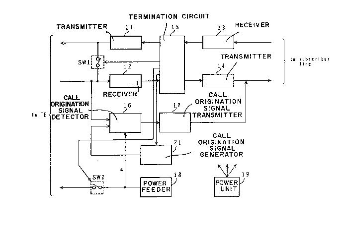
Figure 8 shows in a block diagram the first embodiment
of an NTI according to this invention.
The equipment includes a call origination detector
16 which detects a call origination signal from the terminal
equipment, a call origination transmitter 17 which transmits the
information on the call origination detected by the detector 16 to
the line termination equipment at the telephone office of an ISDN,
and a power feeder 18 which supplies power to the terminal equip-
ment at the customer premises, and further includes a termination
circuit 15 and a switch SWl as a means for sending back a trans-
mitted signal as a loopback control signal from the office. It
further includes a transmitter 11 which transmits signals to the
terminal equipment, a receiver 12 which receives signals from the
terminal equipment, a receiver 13 which receives signals from the
subscrlber lines, and a transmitter 14 which transmits signals to
the subscriber line. It also includes a power unit 19 which
feeds power to respective circuits.
The NTI of this invention is characterized in that it
comprises a call origination signal generator 21 as a means which
generates pseudo-call origination signals to the detector 16 and
the transmitter 17, that the output ~rom the power feeder 18 is
connected to the call orlglnation detector 16 in order to verlfy
the normal oper~tlon of the power unlt, and that there i9 further
provlded a means whlch executes a loopback test only on the
condltion that the pseudo-call origination signal has duly been
transmltted.
-- 8 --
. . ~" , , .
: : : . - - .
20113~
27341-13
The generator 21 outputs a call origination signal
to the detector 16. The detector 16 is supplied with the output
from the power feeder 18.
The operation at the time of activation of the NTI is
identical to that described in relation to Figure ~.
Figure 9 shows an activation sequence for the loopback
test.
The equipment at the telephone office sends out train-
ing pulses to the NTI upon request for subscriber line activation.
The NTI transmlts the training pulses to the equipment at the
office after having established a frame synchronization.
Theequipment at the office transmits a call origina-
tion function test control signal to the NTI by using control bits
out of the frame of the subscriber line after having established
the frame synchronization. The termination circuit 15 resets all
circults of the NTI to an initlalized state when lt detects a
call orlglnatlon functlon test control signal and su~pends all
operatlons. Simultaneously~ the clrcuit 15 opens the swltch SW2
by outputtlng an SW2 drlving slgnal 80 as to prevent the power
feeder 18 from being affected by a fallure on the terminal equlp-
ment.
Subsequently, the generator 21 outputs a call ori-
glnatlon slgnal to the detector 16. When the detector 16 receives
the slgnal, it executes the actlvatlon sequence shown ln Figure 2.
In other words, the detector 16 transmlts the detection output to
the transmltter 17 when it detects a call origination slgnal.
_ g _
. .
2011385
27341-13
The transmitter 17 transmits a call origination signal to the
equipment at the office via a subscriber line. This transmission
is not an authentic one but a psuedo one, and it may be executed
by closing a loop on the subscriber line or sending out a tone
signal.
When the equipment at the telephone office receives
the transmitted call origination signal, it sends out training
pulses to the NTI upon request for activation of the subscriber
line. The receiver 13 conducts an adaptive line equalization when
it receives the training pulses. Upon completion of the adaptive
line equalization and establishment of a frame synchronization,
the transmitter 14 transmits training pulses to the equipment at
the office.
The subscriber line is fully activated by the complet-
ion of adaptive line equalization and frame synchronization
establishment at the equipment at the office. Then, the equipment
transmits a loopback control signal to the NTI by using control
bits out of the downstream subscriber llne frame.
The clrcuit 15 of the NTI detects the control signal,
transmits an SWl drlving slgnal to the ~Wl, and closes a loop for
loopback by turnlng on the swltch.
When the loop 19 formed, the circuit 15 transmlts
the indlcatlon slgnal for loopback to the equipment at the of~ice
by uslng control bits out of the subscrlber line frame. By
receiving the indicatlon slgnal, the equlpment at the office
recognizes the completion of loop formation, and measures an error
-- 10 --
. ~ . .,
.
20113~
27341-13
bit rate by using the loopback path.
In the sequence above mentioned, when either the
detector 16 or the transmitter 17 fails, the NTI cannot notify the
equipment at the office of a call origination even if it has
received a call origination test control signal from the equipment.
Therefore, a failure at the NTI can be detected by the equipment
at the office.
When the power feeder 18 fails, as the detector 16
is supplied with power from the output a of the circuit 18, even
if the NTI receives a call origination control signal from the
equipment at the office, the NTI remains suspended. As a result,
the equipment can detect an abnormality of the NTI. A similar
effect may be achieved by constructing the unit in a manner such
that the transmitter 17 is operated by the output a of the power
feeder 18.
The operatlon of the termination circuit 15 will now
be described. The circuit 15 has a flfth operatlon mode or a call
orlglnatlon function test mode ln addltlon to the four modes of
lnltlal actlvation, communlcation and loopback test. Figure 10
shows the relatlongamong those modes. Figure 11 shows the
operational flow in the communicatlon mode whlle Flgure 12 ~hows
the operational flow in the call orlginatlon function test mode.
The three modes of lnltial, activation and loopback test are
ldentlcal to those ln the prlor art. The other two modes of
actlvatlon and loopback test are respectlvely shown ln Flgures 5
and 7.
-~ . . ' ' ~' ' .,
20113~
\
27341-13
The call origination function test mode is the opera-
tion mode to which the circuit is shifted from the communication
mode when it receives a call origination function test control
signal from the receiver 13, and where it resets the mode to the
activation mode, turns off the switch SW2 and transmits a driving
signal to the generator 21. When the call origination function
test mode ends, the circuit 15 enters the activation mode.
In the operational flow shown in Figure 9, an example
is shown to first transmit a pseudo-call origination signal to
the equipment at the telephone office and then to execute the loop-
back test, which constitutes an essential part of this invention.
As shown in Figure 11, it may execute a call or~gination function
test mode alone when it receives a call origination function test
control signal, and then execute the loopback test alone when it
receives the loopback control signal. Therefore, when the tests
are contlnuou~ly conducted for an NTI, loopback tests alone may be
conducted at the second test and thereafter without generating
pseudo-call origination transmission each time.
Figure 13 shows an embodiment of a call origlnatlon
slgnal generator together with a call orlgination signal detector.
The detector 16 is connected to the terminal equipment
vla a transformer and recelves as lnput call orlglnatlon signal
in pulses from the termlnal equlpment. The detector 16 is a cir-
cult whlch ls used to detect pulse power, and if voltage pulses
are glven to an input thereof from outslde, it recognizes them as
a call origination slgnal. In the embodlment shown in Figure 13,
- 12 -
..... ,............................... '',' ; '
:.. ~. '
201~38~
27341-13
a voltage V (e.g. V = 5 volts) is applied at a capacitor 211 by
closing a switch 213 within a predetermined time period, and the
capacitor 211 is connected to an input of the detector 16 by
turning on the switch 212 by a driving signal from the termina-
tion circuit 15. Changes in voltage caused by discharging of the
capacitor 211 are detected as a call origination signal by the
detector 16. If the voltage V is supplied from the feeder 18, the
operation of the circuit ~ay be checked simultaneously.
Figure 14 is a block diagram to show the second
embodiment of this invention NTI.
The second embodiment differs from the first one in
that it outputs a call origination signal directly from the circuit
termination 15 in~tead of employing the generator 21 used in the
first embodiment. The second embodiment i9 simpler in structure
than the first one.
The circuit termination 15 generally comprlses ICs
~integrated circults) which easily allow an addition o~ extra
~unctions for outputtlng a call origination signal. The activa-
tion se~uence at the loopback test and the operation modes of
thls embodiment are identical to those in the first embodlment.
Figure 15 i9 a block diagram to show the third embodi-
ment of the NTI according to thls invention.
The clrcuit structure in the third embodlment ls
further simplified as lt can execute loopback tests wlthout using
the call origination signal generator 21 used in the first
embodlment.
- 13 -
,. :
'~:
20113~
27341-13
Figure 16 shows the activation sequence at the loop-
back test in this embodiment which differs from the first embodi-
ment shown in Figure 9 in the operation to be taken when it
receives a call origination function test control signal from the
equipment at the office.
More particularly, this embodiment temporarily resets
all circuits of the NTI after receiving the call origination
function test control signal, turns off the switch SW2 and turns
on the switch SWl. Then the terminatlon circuit 15 outputs a call
origination signal which is supplied to the call origination
signal detector 16 via the transmitter 11 and the switch SWl. The
sequence in the subsequent procedure is identical to that in the
flrst embodiment.
Figure 17 shows the operation flow in the call ori-
gination function test mode at the circuit termination to execute
the activation sequence. The flow differs from the first embodi-
ment in that it outputs an SWl driving signal after having out-
putted an SW2 driving signal. Other flow and the operation modes
other than the call origination functlon test mode are identical
to those ln the first embodlment.
Figure 18 is a block dlagram to show the fourth
embodlment NTI accordlng to thls invention.
This embodlment differs from the first embodlment in
that the output b of the call origination transmitter 17 is
supplied to the termination circuit 15.
Figure 19 shows the activation sequence at the loop-
- 14 -
..
, , , ;~
20113~
27341-13
back test in this embodiment which differs from the sequence shown
in Figure 9 by the operation to be taken upon receipt of a call
origination function test control signal from the equipment at
the office.
More specifically, when it receives a call origination
function test control signal, it feeds the call origination signal
from the generator 21 to the detector 16 instead of resetting the
NTI. As a result, the circuit 15 can transmit a signal indicating
that the result of the call origination test was good to the
equipment at the office using status indication bits at the
allocated position within the upstream subscriber line frame after
a call originatlon signal is outputted at the output b of the
transmitter 17. The equipment at the office learns by the above
procedure that all the functions of the detector 16 and of trans-
mitter 17 which operate when activated by an incoming call and of
the power feeder 18 which supplles power to the terminal equipment
are normal. Then, all the circuits of the NTI are reset, the
switch SW2 is turned off, and a call origlnation signal is fed
from the generator 21 to the detector 16. The subsequent sequence
is ldentical to that in the first embodlment.
Flgure 20 shows the operatlonal flow of the clrcult
termlnatlon in the call origination functlon test mode for exe-
cutlng the sequence. It differs from the first embodiment in that
the transmission of a driving signal to the generator 21 and the
receipt of a call origination transmission signal from the line b
are verified, but other flow and operation modes other than the
- 15 -
,
~ ' . .- ' '' .: ~
20~3~
27341-13
call origination test mode are identical to those in the first
embodiment.
Figure 21 is a block diagram to show the fifth embodi-
ment of the NTI according to this invention.
A power feeder circuit such as 18 is provided with a
protector 22 for short circuits which protects the feeder when the
output is short-circuited and a circuit block for power feeding
23 which generates power. The protector 22 can electrically
disconnect the power output.
This embodlment is simplified in circuit structure by
omitting the switch SW2 used in the first embodiment. More
particularly, the protector 22 is controlled by the control signal
of power feeder disconnection from the termlnation circuit 15. The
activation sequence is identical to the one in the first embodi-
ment.
In the above embodiments, description has been made
for the case where the operation of the power feeder 18 is veri-
fied by the voltage at the output a. However, this invention may
be realized by structuring the circuit so that a load is inserted
at the output a for testing power. In this case, it can detect a
failure whlch cuts the power even if the output voltage from the
circuit 18 remalns wlthin the normal scope.
As ls described in detail ln the foregoing statement,
the NTI of thls lnventlon first verifies lf the circuits whlch
should operate at the tlme of actlvatlon by an lncoming call from
the termlnal equlpment and a power feeder which supplles power to
- 16 -
'~'' ' ' ' ' -
. .,, :
20113~
28341-13
the equipment are operating normally or not and then executes a
- loopback test. This allows the NTI according to this invention
to test all the functions thereof including those of activation
by an incoming call and of power feeder simply by conducting a
loopback test.
- 17 -