Note: Descriptions are shown in the official language in which they were submitted.
:G ~:
2011~7~
CASTOR
This invention relates to castors, and more
particularly to castors comprising a wheel rotatably
mounted to a body member by a spindle which extends
from a spindle mount carried by the body member into a
closed bore in a central boss of the wheel.
Such a castor is disclosed in our British patent
specification 2171897. In such castors grease is
normally provided between the surface of the closed
bore of the wheel's central boss and the end of the
spindle received therewithin. If too much grease is
provided, there is a tendency for it to seep from the
axial gap between the boss at the open end of the
bore and the spindle mount. This in itself may cause
problems in use, but in any event, when the castor
wheel and/or body member are made of electrically
chargeable material, such as synthetic plast cs, dust,
fluff and other debris tends to adhere to the seeped
grease until such time as the accumulated mass
dislodges from the castor to become deposited on and
spoil the floor surface on which the castor is being
used. This is particularly disadvantageous when the
floor surface is a light-coloured carpet.
In order to mitigate the above-mentioned problem
and/or allow greater tolerance in the amount of grease
provided between the closed bore of the central boss
.~ ~
, ;
` ~ 20~1~7~
of the wheel and the spindle, we have now provided a
castor comprising a wheel rotatably mounted to a body
member by a spindle which extends from a spindle mount
carried by the body member into a closed bore in a
central boss of the wheel, wherein a shroud means
shrouding the boss and/or spindle mount bridges the
axial gap therebetween and extends the seepage path
for grease provided between the closed bore of the
boss and the spindle.
In one embodiment of the invention, the shroud
means is integral with the spindle mount and extends
about an end portion of the boss from which the
spindle emerges. In this embodiment the shroud means
may advantageously be formed as a counterbore in said
spindle mount for receiving said boss end portion.
In the above-mentioned embodiment, the boss end
portion has an external surface which is circular in
cross-section and the shroud means has an internal
surface which is also circular to allow rotation of
the boss end portion relative to the shroud means. In
a modified embodiment, the shroud means has an
internal surface which is substantially oval in cross-
section to allow vertical movement of the boss end
portion relative to the shroud means in addition to
the aforementioned relative rotation.
In another embodiment the shroud means is
: 20~7~
. .
integral with the boss and extends about an end
portion of the spindle mount from which the spindle
extends. In this embodiment the shroud means is
formed by a counterbore in said boss for receiving
said spindle mount end portion.
In another embodiment, the shroud means is a
tubular element, respective opposite end portions of
which receive an end portion of the boss from which
the spindle emerges and an end portion of the spindle
mount from which the spindle extends. The above-
mentioned tubular element may be resilient and/or
formed of a grease absorbent material.
In all of the illustrated embodiments the spindle
mount is integral with the body portion of the castor,
but it is to be understood that this is not essential
since for example the spindle mount may be carried by
the body member for relative movement thereto, as for
example in an arrangement as disclosed in our British
patent specification 2195237.
In order that the invention may be better
understood, the above-mentioned embodiments thereof,
which are given by way of example only, will now be
described with reference to the accompanying drawings,
in which:
Figures 1 to 3 are respectively side, front and
top plan views of a twin wheel castor;
~ ~ .
2011 ~
Figure 4 is a cross-sectional view of the same
castor;
Figure 5 is a perspective fragmentary exploded
view showing the body member and a wheel of the
castor;
Figure 6 is a view similar to Figure 5 of a
modified castor; and
Figures 7 and 8 are respective views similar to
Figure 4 of two other castors.
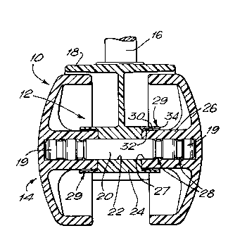
Referring first to Figures 1 to 3, the
illustrated castor generally comprises a body member
12, of a plastics material, for example a polyamide,
or a metal, two plastics castor wheels 14 mounted to
the body and a metal stem 16 extending from and
rotatable in the body 12 for mounting the castor on a
piece of furniture. The body 12 also includes a hood
18 which extends over the wheels.
Referring now to Figure 4, the two wheels 14 are
rotatably mounted on respective end portions 19 of a
spindle 20, which is mounted in a through-bore 22 of a
spindle mount 24 of the body 12 so as to extend from
the spindle mount on each side thereof. As
illustrated, the spindle mount 24 is integral with the
body and formed as a boss. Each wheel 14 is provided
with a respective central boss 26 provided with a
closed bore 27 into which the spindle end 19 extends.
','' ~
201~
Each wheel is axially retained on its respective
spindle end portion 19, by interengaging groove and
rib means 28 of the spindle end portion and closed
bore of the boss. As illustrated, these groove and
rib means take the form disclosed in our
aforementioned UK Patent 2171897. Specifically, each
closed bore is formed with two radially inwardly
projecting circumferentially extending annular ribs
which are spaced along the bore and which are received
in annular grooves in the spindle end portion.
Furthermore, the circumferentially extending annular
ribs formed in the bore are provided with gaps in
their circumferential extents for the reasons
disclosed in the above-mentioned UK patent, which
reasons include allowing grease deposited in the bore
before the spindle is inserted to be spread evenly
over the wall of the bore and complementary surfaces
of the spindle during insertion of the spindle end
portion into the bore.
As mentioned previously seepage of grease from
the axial gap between the end portion of the boss 26
adjacent the open end of the bore and the spindle
mount 24 may occur if too much grease is initially
deposited in the bore, thus resulting in the
aforementioned problem of fluff, dust and other debris
becoming adhered to that grease and eventually
" ~
rl ~
accumulating into a mass which becomes dislodged from
the castor and drops to the floor. In order to avoid
this problem, the illustrated castors are each
provided with a respective shroud means associated
with each wheel 14 shrouding the wheel boss and/or the
spindle mount which bridges the axial gap
therebetween and extends the seepage path for grease
provided between the closed bore of the wheel boss and
the spindle.
In the embodiment shown in Figures 1 to 5 the
shroud means is integral with the spindle mount 24 and
extends about the end portion of the wheel boss 26
from which the spindle emerges. The shroud means is
designated 29 in Figures 4 and 5 and is formed by a
counterbore in the spindle mount 24 for receiving the
wheel boss end portion. The external surface 30 of
the wheel boss end portion and the internal surface 32
of the shroud 29 are each circular in cross-section to
allow rotation of the wheel boss relative to the
shroud. The arrangement extends the seepage path for
grease axially beyond the axial gap between the wheel
boss 26 and spindle mount 24 over the wheel boss end ;
portion between the surfaces 30 and 32 to the free end
34 of the shroud 29. We have also noted that dust,
fluff and other debris tends to form a plug at the
.
end of the radial gap between the two surfaces 30, 32
'' ~""' '''
: :
2 ~
- `
adjacent the end 34 of the shroud 29.
In the illustrated castor, in which the wheel has
a diameter of 5cm, the wheel boss 26 has a diameter of
about 1.25cm, and the closed bore has a depth of about
1.8cm and a diameter of about .9cm we have found that
satisfactory results are obtained where there is a
0.25mm radial gap between the surfaces 30, 32 and the
shroud 29 has an axial length of .5cm. It is to be
understood that these dimensions, and thus the ratios
they have with each other, are given merely by way of
example. Nevertheless it is considered that the
radial gap between the shroud and wheel boss should be
about 2% of the boss diameter and the length of the
shroud extending over the boss should be at least 40%
of the boss diameter.
A modification of the above-described embodiment
is illustrated in Figure 6, in which parts
corresponding to those shown in Figure 5 have been
given the same reference numerals increased by 100.
The spindle mount 124 of the castor is integral with
the body 112 and allows the spindle (not shown) and
wheels 114 thereon (only one shown) to move
substantially vertically relative to the body 112 as
illustrated, by virtue of the through bore 122 of the
spindle mount being substantially oval in cross-
section. The internal surface 132 of the shroud 129
.. . .. . . ..
2 0 ~
,
integrally formed with the spindle mount is also
substantially oval in cross-section to allow
corresponding substantially vertical movement of the
wheel boss 126, the external surface 130 of which is
circular in cross-section, relative to the shroud 129
in addition to rotation of the wheel boss 126 within
the shroud 129. In this case it is considered that
the radial gap between the shroud and wheel boss at
the minimum diameter of the shroud should be about 2%
of the boss diameter and as before the length of the
shroud extending over the boss should be at least 40%
of the boss diameter.
Figure 7 shows an aiternative embodiment to that
shown in Figures 1 to 5. In Figure 7 parts
corresponding to those shown in Figure 4 have been
given the same reference numerals increased by 200.
In the embodiment shown in Figure 7, the shroud means
229 associated with each wheel 214 is integral with
the wheel boss 226 and extends about an adjacent end
portion of the spindle mount 224 from which the
:.
spindle 220 extends. As illustrated, the shroud means
229 is formed by a counterbore in the wheel boss 226
for receiving an end portion of the spindle mount.
The external surface of the spindle mount end portion
and the internal surface of the shroud 229 are
circular in cross-section. This arrangement extends
2 0 1~
-
the seepage path for grease axially beyond the axial
gap between the wheel boss 226 and spindle mount 224
over the spindle mount end portion between the
surfaces 230 and 232 to the free end 234 of the
shroud. In this case, the radial gap between the
shroud and the spindle mount should be about 2~ of the
diameter of the wheel boss and the axial length of the
shroud extending over the spindle mount should be at
least 40% of the boss diameter for best results.
It will be noted that in the above described
embodiments the end portion of the wheel boss adjacent
the open end of the bore therein and the end portion
of the spindle mount adjacent thereto are fitted one
within the other, one of these end portions being
provided with a counterbore to form a shroud integral
with that end portion and extending over the other end
portion.
Referring now to Figure 8, there is shown another
embodiment. In Figure 8, parts corresponding to those
shown in Figure 4 have been given the same reference
numerals increased by 300. In the embodiment shown in
Figure 8, the shroud means associated with each wheel
314 comprises a tubular element 329 formed separately
from the wheel boss 326 and spindle mount 324.
Respective end portions 50, 52 of the tubular element
329 receive an end portion of the wheel boss 326 from
i ~ , ,, , , . . '
- 2011~;~J~
which the spindle 320 emerges and an end portion of
the spindle mount 324 from which the spindle 320
extends. These end portions each have an external
surface which is circular in cross-section and the
internal surface of the end portions 50, 52 of the
tubular element are each circular in cross-section.
As illustrated the diameter of the external surface of
the spindle mount end portion is greater than that of
the external surface of the wheel boss end portion and
the interior of the tubular element 329 is stepped
such that the internal surfaces of the end portions
50, 52 thereof closely cooperate with these external
surfaces. The stepped interior of the tubular element
limits movement thereof towards the spindle mount and
movement away therefrom is limited by engagement of
the tubular element with the ribs 54 on the wheel 314
(or other means - not shown - provided thereon). In
any event it is preferred to locate the tubular
element so that it does not move axially with respect
to the wheel. The tubular element is a loose fit on
both the wheel boss and spindle mount. Alternatively
the tubular element may be a force fit on either the
wheel boss or the spindle mount but not both as it has
to allow relative rotation therebetween. Preferably
the tubular element is resilient. The radial gap
between the tubular element and the wheel boss and/or
3 ~
201~
. -
the spindle mount should be about 2~ of the diameterof the wheel boss and the length of the tubular
element which forms a shroud (i.e. the length of that
portion of the tubular element which has a radial gap
with the wheel boss and/or the spindle mount should be
at least 40% of the wheel boss diameter for best
results.
Whilst the tubular element 329 may be formed of a
plastics material which would not absorb grease which
has seeped from between the spindle 320 and the closed
bore 327 of the wheel boss 326, it is envisaged that
the tubular element may be formed of a grease
absorbent material, for example felt.
In the embodiment illustrated in Figure 8, it
will be appreciated that the tubular element 329
extends the seepage path axially beyond the axial gap
between the wheel boss 326 and spindle mount 324 over
both the wheel boss and the spindle mount between the
external surfaces thereof and the internal surfaces of
the tubular element.
From the foregoing it will be appreciated that
the shrouds provided in the illustrated castors act
to confine small grease seepages from the closed
bores of the wheel bosses and additionally to prevent
dust, fluff and other debris adhering to such
seepages. Thus, the illustrated castors allow greater
2 0 ~
.
tolerance in the amount of grease which is deposited
in the bores during assembly of the castors prior to
insertion of the spindle end portion therein.
It will also be appreciated that best results are
obtained with the embodiments when the axial length
of the shroud is at least 40% of the wheel boss
diameter and preferably also where the radial gap
between the shroud and the wheel boss and/or the
spindle mount over which the shroud extends is about
2% of the wheel boss diameter.
Further, in all of the illustrated embodiments
the facing surfaces of the shroud and the wheel boss ~ -~
and/or the spindle mount over which the shroud extends
are parallel and co-axial with the axis of the spindle.
.
'~. L