Note: Descriptions are shown in the official language in which they were submitted.
201~159~
APPARATUS AND METHOD FOR DETECTING ABNORMALITIES
IN INTRAVASCULAR INFUSION
BACKGROUND OF THE INVENTION
Field of the Invention: This invention generally relates
to an apparatus and method for monitoring intravascular
infusion of parenteral fluid from a parenteral fluid delivery
system to a patient, and more particularly relates to numer-
ical, objective evaluation of effectiveness of intravascular
fluid delivery, by monitoring fluid flow parameters of resis-
tance and compliance.
Description of Related Art: Systems for infusingparenteral fluids intravenously to a patient by means of an
infusion pump typically include a bottle of parenteral fluid,
and an intravenous (IV) set which includes a drip chamber,
flexible plastic tubing extending from the drip chamber, and
a cannula at the end of the tubing to be inserted into a
patient's blood vessel for delivery of the parenteral fluid.
An infusion pump, such as a peristaltic pump, is typically
used for driving the parenteral fluid through the tubing at
a desired rate. Common problems in such a system are that the
fluid flow may become occluded, that the needle inserted into
a patient's vein may be dislodged, or that the discharge tip
of the needle becomes partially dislocated so as to deliver
fluid in adjacent interstitial tissue, which may cause seri-
ous injury.
Systems have been devised for the detection ofabnormalities in an intravascular infusion system, by use of
simple monitoring of the infusion pressure. A high or
increasing pressure may be interpreted as either an infiltra-
2011595
tion or an occlusion. A low pressure may be interpreted asas an unobstructed line. However, the pressure required to
achieve a given flow in an intravascular system depends on
many factors, such as motion and position of the patient,
respiration and arterial or venous blood pressure of the
patient, and the size and position of the cannula used. Such
factors create a considerable uncertainty in the measurement
of pressure, and may cause difficulty in interpretation of
pressure readings. Observation of a pressure response of the
lo fluid delivery system, to determine whether pressure returns
to a normal steady state equilibrium within a given time
period can give some information as to effectiveness of fluid
delivery. Application of fluid flow excitation pulses and
comparison of pressure responses of the system against a
reference value is also known.
It would be desirable to provide a system for monitoring
fluid in an intravascular parenteral fluid delivery system
which provides a measure of resistance to fluid flow and a
measure of compliance of the patient's tissue. Resistance to
flow is appropriate for monitoring flow to an infusion site,
since it can indicate such problems as having the end of the
cannula pressed against the vein or artery wall, the cannula
being infiltrated into the tissues surrounding the vessel, and
certain medical problems such as phlebitis which involve
constriction of the vessel. Compliance may be used for
distinguishing the location of the cannula due to a
significant difference between the compliance of a vein and
the compliance in interstitial tissue.
SUMMARY OF THE INVENTION
30 The present invention provides a system and method for
de'tecting abnormalities in infusion of parenteral fluid in a
CA 02011~9~ 1998-12-02
parenteral fluid delivery system having a normal equilibrium
flow rate, to provide an indication of the resistance and
compliance of the entire fluid flow system, including the
patient venous system, by comparing at least one of the
indications of the system with a corresponding reference
value.
Briefly, and in general terms, the system for
detecting abnormalities in infusion of parenteral fluid
delivery system to a patient comprises a) infusion means for
producing a perturbation of said fluid flow by varying the
rate of fluid flow from an equilibrium flow rate with a
specific volume of fluid; b) sensor means for measuring
pressure of said fluid over a period of time and adapted to
generate a signal representing a pressure response of said
fluid to said perturbation and a signal representing an
equilibrium pressure level; c) first integrator means
operatively connected to said sensor means for determining a
first integral of the difference between said equilibrium
pressure signal and said pressure response signal over time,
and for generating a signal representing said first integral;
d) means for determining resistance to said infusion of fluid
from the delivery system adapted to scale said first integral
signal according to said specific volume, and for producing a
signal representing the resistance to fluid flow; e) second
integrator means for determining a second integral by
multiplying the difference between said pressure response
signal over time and said equilibrium pressure signal by a
value representing said time, and integrating the resultant
product with respect to said time, and adapted to generate a
signal representing said second integral determined; and
f) means responsive to said first and second integrator means
for determining compliance of said fluid delivery system by
dividing said second integral signal by said first integral
signal to produce a signal representing an effective time
constant, and by scaling said effective time constant by said
previously determined resistance to produce a signal
representing compliance of said fluid delivery system.
66239-1581
CA 02011~9~ 1998-12-02
The method of the lnventlon, brlefly and generally,
also concerns the detectlon of abnormalltles ln lnfuslon of
parenteral fluld from a parenteral fluld dellvery system to a
patlent comprlses the steps of: a) produclng a perturbatlon of
sald fluld flow by varylng the rate of fluld flow from an
equlllbrlum flow rate wlth a speclflc volume of fluld; b)
measurlng the pressure of sald fluld over a perlod of tlme,
generatlng a slgnal representlng an equlllbrlum pressure
level, and generatlng a slgnal representlng a pressure
response of sald fluld to sald perturbatlon; c) determlnlng a
first lntegral of the dlfference between sald equillbrlum
pressure slgnal and sald pressure response slgnal overtlme,
and generatlng a slgnal representlng sald flrst lntegral;
d) determlnlng reslstance to fluld flow ln the dellvery system
by scallng sald flrst lntegral slgnal accordlng to sald
speclflc volume, and generatlng a slgnal representlng
reslstance to fluld flow; e) determlnlng a second lntegral by
multlplylng the dlfference between sald pressure response
slgnal over tlme and sald equlllbrlum pressure slgnal by a
value representlng sald tlme, and lntegratlng the resultant
product wlth respect to sald tlme, and generatlng a slgnal
representlng sald second lntegral; and f) determlnlng
compllance of the fluld dellvery system by dlvldlng sald
second lntegral slgnal by sald flrst lntegral slgnal to
produce a slgnal representlng an effective tlme constant of
sald fluld dellvery system and scallng sald tlme constant
slgnal by sald prevlously determlned reslstance to produce a
slgnal representlng compllance of sald fluld dellvery system.
Accordlng to a more speclflc aspect, the lnventlon
provldes a system for determlnlng compllance ln the lnfuslon
of a fluld to a patlent by a fluld dellvery system, the fluld
dellvery system havlng an equlllbrlum flow rate, comprlslng:
a) an lnfuslon pump for produclng a perturbatlon ln the fluld
flow by varylng the rate of fluld flow from the equlllbrlum
flow rate wlth a speclflc volume of fluld; b) a pressure
sensor for measurlng the pressure of the fluld ln the fluld
dellvery system over a perlod of tlme and adapted to provlde a
66239-1581
CA 02011~9~ 1998-12-02
perturbation pressure slgnal representlng the pressure
response of sald fluld to sald perturbatlon and an equlllbrlum
pressure slgnal representlng an equlllbrlum fluld pressure;
c) a reslstance calculator for determlnlng the reslstance to
the lnfuslon of fluld and provldlng a reslstance slgnal
representatlve thereof; d) a flrst lntegrator whlch recelves
the perturbatlon pressure slgnal and the equlllbrlum pressure
slgnal and determlnes a flrst lntegral of the dlfference
between sald equlllbrlum pressure signal and said perturbation
pressure signal over time, and for providing a pressure
difference signal representative thereof; and e) a compliance
calculator which recelves the perturbatlon pressure slgnal and
the equlllbrlum pressure slgnal and determlnes a second
lntegral by multlplylng the dlfference between the
perturbatlon pressure slgnal and sald equllibrlum pressure
signal over time by a value representlng sald tlme, and
lntegratlng the resultant product wlth respect to said tlme,
and adapted to provlde a compllance slgnal representlng sald
second lntegral dlvlded by said first integral, the quotlent
of whlch ls dlvlded by the reslstance slgnal.
According to another specific aspect, the invention
provides a system for detectlng abnormalltles ln lnfuslon of
fluld to a patlent from a fluld dellvery system the fluld
dellvery system havlng an equlllbrlum flow rate, comprlslng:
a) an lnfuslon pump for produclng a perturbation in the fluid
flow by varylng the rate of fluld flow from the equlllbrlum
flow rate wlth a speclflc volume of fluld; b) a pressure
sensor for measurlng the pressure of the fluld ln the fluld
dellvery system over a perlod of tlme and adapted to provlde a
perturbatlon pressure slgnal representlng the pressure
response of sald fluld to sald perturbatlon and an equlllbrlum
pressure slgnal representlng an equlllbrlum fluld pressure;
c) a reslstance calculator for determlnlng the reslstance to
the lnfuslon of fluld and provldlng a reslstance slgnal
representatlve thereof; d) a flrst lntegrator whlch receives
the perturbation pressure signal and the equilibrium pressure
signal and determines a first integral of the difference
66239-1581
CA 02011~9~ 1998-12-02
between said equlllbrlum pressure slgnal and sald perturbatlon
pressure signal over tlme, and for provldlng a pressure
dlfference slgnal representatlve thereof; e) a compllance
calculator whlch recelves the perturbatlon pressure slgnal and
the equlllbrlum pressure slgnal and determlnes a second
lntegral by multlplylng the dlfference between the
perturbatlon pressure slgnal and sald equlllbrlum pressure
slgnal over tlme by a value representlng sald tlme, and
lntegratlng the resultant product wlth respect to sald tlme,
and adapted to provlde a compllance slgnal representlng sald
second lntegral dlvlded by sald flrst lntegral, from the
quotlent of whlch ls subtracted a flow factor whlch ls
proportlonal to the tlme of flow perturbatlon of the speclflc
volume of fluld, all of whlch ls dlvlded by the reslstance
slgnal; and f) an alarm comparator whlch recelves the
reslstance slgnal and compares lt to a threshold value and
provldes an alarm based on the comparlson and recelves the
compllance slgnal and compares lt to a threshold value and
provldes an alarm slgnal based on the comparlson.
The prlnclples on whlch the lnventlon ls based are
baslcally as follows:
If a known quantlty of fluld ls ln~ected lnto a
patlent through a fluld dellvery system whlch ls essentlally
ln equlllbrlum (though not necessarlly at zero flow), lt wlll,
ln general, cause a rlse ln the pressure. The pressure rlse
may be sudden or slow, and may even be osclllatory lf the
hydraullc system ls of second or hlgher order and ls
underdamped. If the ln~ectlon of fluld ls now stopped, and lf
the system has an outlet, fluld wlll leave the system untll lt
ls agaln ln equlllbrlum wlth lts surroundlngs. Unless the
hydraullc system ls permanently deformed by the fluld ln~ected
lnto lt, the amount of fluld leavlng wlll be equal to the
amount of fluld whlch entered.
If the outflow of fluld as a functlon of tlme (t),
due to the dlfference ln pressure between the system and lts
surroundlngs, ls deslgnated "F(t)", the background or
equlllbrlum flow ls deslgnated by ~Feq~ the pressure as a
66239-1581
CA 02011~9~ 1998-12-02
- 6a -
functlon of time (t) wlthln the system ls deslgnated by
"P(t)", and the equlllbrlum pressure ls deslgnated by "Peq"~
then the reslstance to flow may be deflned by
R = P(t) - Peq Eq. 1
F(t) - Feq
The tlme-varying pressure, P(t), ls readlly
measured. The tlme-varylng flow, F(t) ls not.
Rearranglng Eq. (1):
10R (F(t) - Feq) = P(t) - Peq~ Eq. 2
lntegrate both sldes over tlme. Slnce R ls a constant,
R ¦~ (F(t) - Feq)dt = ¦~(P(t) - Peq)dt~ Eq. 3
or ¦~(P(t) - Peq)dt
R = , Eq. 4
¦~(F(t) - Feq)dt
But the denomlnator ls ~ust
¦~(F(t) - Feq)dt = Q Eq. 5
whlch ls the known quantlty of fluld ln~ected lnto the
system. Thus,
¦~ (P(t) - Peq)dt
R = , Eq. 6
Q
The measurement of compliance may be understood by
consldering a parallel reslstance-compllance model. The
pressure ls glven by
' t
eq - c (( F (t ) - Feq) - P(t') Peq )dt'. Eq. 7
O R
Integratlng both sldes wlth respect to t glves
¦ O (P(t) - Peq)dt = 1 c ¦ O ¦ O (F(t') - Feq) dt' dt
66239-1581
CA 02011~9~ 1998-12-02
- 6b -
~c J oT r to ( P ( t ) - Peq) dt dt Eq. 8
integrating the double integrals by parts gives
~T
I o (P(t) - Peq)dt Eq. 9
= 1 J O (F(t) - Feq)dt - J t (F(t) - Feq)dt
O
RC J o (P(t) - Peq) dt - J t(P(t) - Peq)dt
O
By using Equation 3 and letting T approach infinity,
where Teff is the effective time of response, the final result
ls
I O t(P(t) - Peq)dt Jo t(F(t) - Feq)dt
Teff = RC = - . Eq. 10
00 x
Jo (P(t) - Peq)dt Jo (F(t) - Feq)dt
Thls derlvatlon is not rlgorous; it is possible to
show, however, that if the system is in equilibrium with its
surroundings before the fluid is in~ected into it, and the
lntegral ls done over sufflclent time for the system to again
return to equilibrlum, then Eq. 6 glves the total resistance
to flow from the point of the pressure measurement to the
ambient pressure sink into which the system drains. The value
of resistance so obtained is unaffected by any combination of
compliances and inertances. Their only effect is to determine
the time required for the system to return to equilibrium.
66239-1581
.
CA 02011~9~ 1998-12-02
-- 6C --
Slmllarly, Eq. 10 glves the effectlve tlme constant
(Teff) of the system. An effective compliance may be obtained
by dividing the effectlve tlme constant by the total
reslstance obtalned from Eq. 6.
The lntegrals,
I t(F(t)~Feg)dt
o
J (F(t)~Feq)dt
66239-1581
which appear in the equations above areto be evaluated from
the known timing and flow characteristics of the infusion pump
or other flow control device.
The methods described do not require that the
"equilibrium state" be a state of zero flow. The equilibrium
is rather a dynamic one, which is monitored and determined
periodically. It is only necessary for the hydraulic system
to be in equilibrium prior to the injection of the bolus, and
the pressure response be integrated until it again returns to
equilibrium. The baseline pressure, Peqr is then the average
pressure tincluding that due to flow) in the equilibrium
state, and Q is the difference between the fluid volume
delivered and that volume which would have been delivered had
there been no bolus injected to perturb the system. In this
case, it should be noted that the "bolus" may be negative.
That is, the measurement of resistance may be made by using
a decrease or an interruption of flow. In this case, Q will
be negative. Other patterns of flow perturbation, such as
alternatively increasing and decreasing the flow rate, may
also be used and have the potential advantage of'providing a
greater immunity to error caused by pressure changes due to
other causes.
It is not even necessary that the "equilibrium state" be
a steady state. It has been shown experimentally that if the
integrals in Eqs. 6, 10, and 11 are evaluated synchronously
with the repetitive or cyclic action of a peristaltic pump,
then the values so obtained are stable with time, and
accurately report the resistance and compliance.
It is also important to note that the method puts no
limit on the size, duration, or rise time of the injected
bolus. It is sufficient to start with the system in
equilibrium, perturb the flow, and integrate the difference
between the resulting pressure response and the equilibrium
;
201159~
pressure until equilibrium is again achieved. The integration
provides a natural filter which minimizes the effects of
vibration of the infusion set tubing, and patient motion.
Since the length of the flow perturbation is not related to
the time required for equilibrium to return, it can be made
quite short, which provides a major advantage at low flow
rates. A short pulse of fluid can be used, which, since it
represents a high instantaneous rate, will produce an easily
measurable pressure response. The volume can still be quite
small, on the order of a few microliters. At higher rates,
rather than waiting for equilibrium to return, integration
taken over the period of perturbation rèduces the length of
time required for a resistance measurement. Clinically, this
means that in the case of an infiltration, less fluid is
delivered into the tissue before the condition islindicated.
Other aspects and advantages of the invention will become
apparent from the following detailed description, and the
accompanying drawings, illustrating by way of example the
features of the invention.
BRIEF DESCRIPTION OF THE DRAWINGS
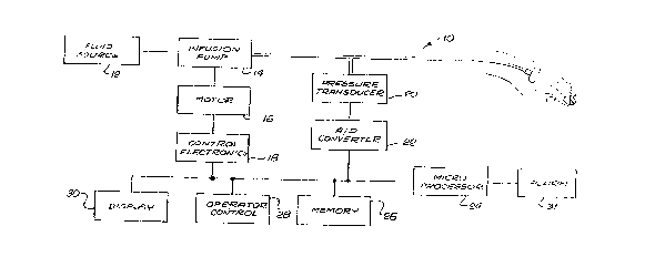
FIGURE 1 is a simplified block diagram of a system for
detecting abnormalities in intravascular infusion of
parenteral fluid from a parenteral fluid delivery system to
a patient;
FIG. 2 is a schematic diagram illustrating a system for
determining and operating upon the fluid flow parameters of
resistance and compliance;
FIG. 3 illustrates a flow chart of the controlling
algorithm performed by the system;
FIG. 4 is a graphical representation of pressure response
and equilibrium pressure sensed by the system.
5 ~ ~
DETAILED DESCRIPTION OF THE INVENTION
As is shown in the drawings for purposes of
illustration, the invention is embodied in a system and method
for detecting abnormalities in infusion of parenteral fluid
from a parenteral fluid delivery system to a patient which
normally operates at an equilibrium pressure level. The
parenteral fluid delivery system is herein defined as
including not only the tubing of the fluid administration
system, but also the venous system and tissue of the patient,
since the venous and tissue response of the patient affect the
effectiveness of the fluid administration as well, and are,
practically speaking, of primary interest. The detection
system provides an indication of the resistance and compliance
based upon the monitoring of fluid pressure. The detection
system is particularly suited for use at low flow rates,
although it is not limited to low flow rates.
In accordance with the invention, there is provided
a system for detecting abnormalities in infusion of parenteral
fluid from a parenteral fluid delivery system to a patient,
the system having an equilibrium flow rate, and comprising
infusion means for producing a perturbation of the fluid flow
by varying the rate of fluid flow from the equilibrium flow
rate with a specific volume of fluid; sensor means for
measuring pressure of the fluid over a period of time adapted
to generate a signal representing a pressure response of the
fluid to the perturbation and a signal representing an
equilibrium pressure level; first integrator means for
determining a first integral of the difference between the
equilibrium pressure signal and the pressure response signal
over time, and adapted to generate a signal representing the
first integral; means for determining resistance to fluid flow
66239-1581
B
2011~9~
in the delivery system adapted to scale the first integral
signal according to the specific volume to produce a signal
representing resistance to fluid flow; second integrator means
for determining a second integral by multiplying the
difference between the pressure response signal over time and
the equilibrium pressure signal by a value representing the
time, and integrating the resultant product with respect to
the time, and adapted to generate a signal representing the
second integral; and means for determining compliance of the
fluid delivery system by dividing the second integral signal
by the first integral signal and scaling the resultant
quotient according to the previously detèrmined resistance to
produce a signal representing complian~e-of the fluid delivery
system.
The invention also provides for a method o;f detecting
abnormalities in infusion of parenteral fluid from a
parenteral fluid delivery system to a patient, the system
having an equilibrium flow rate, comprising the steps of
producing a perturbation of the fluid flow by varying the rate
of fluid flow from the equilibrium flow rate with a specific
volume of fluid; measuring the pressure of the fluid over a
period of time, generating a signal representing an
equilibrium pressure level, and generating a signal
representing a pressure response of the fluid to the
perturbation; determining a first integral of the difference
between the equilibrium pressure signal and the pressure
response signal over time, and generating a signal
representing the first integral; determining resistance to
fluid flow in the delivery system by scaling the first
integral signal according to the specific volume, and
generating a signal representing resistance to fluid flow;
determining a second integral by multiplying the difference
between the pressure response signal over time and the
2011~9a
-
equilibrium pressure signal by a value representing the time,
and integrating the resultant product with respect to the
time, and generating a signal representing the second
integral; determining compliance of the fluid delivery system
by dividing the second integral signal by the first integral
signal to produce a signal representing an effective time
constant of the fluid delivery system, and scaling the time
constant signal by the previously determined resistance to
produce a signal representing compliance of the fluid delivery
system.
As is shown in the drawings, a parenteral fluid delivery
device 10 includes a fluid source 12, connected to an infusion
pump 14, which is preferably a peristaltic pump, driven by a
motor 16, and having control electronics 18 for governing the
lS infusion pump for producing perturbations of the fluid flow
by varying the rate of fluid flow with respect to the
equilibrium flow rate. The infusion pump provides a specific
volume of fluid in producing the perturbation, although the
volume and pressure may actually be a negative value. For
example, the fluid flow rate may be increased above the
original flow rate, then allowed to return to the original
flow rate, and decreased to a rate below the original fluid
flow rate, before finally returning the flow rate to the
original rate. The volume may be predetermined or may be
dynamically determined, to suit the requirements for
meaningful measurements. The control electronics may include
a variable duty cyclic controller, to allow production of
cyclic perturbation, which can be varied either in a
predetermined manner, or may also be dynamically according to
requirements for meaningful measurements. The infusion pump
is preferably adapted to produce either long or short pulses
of flow, which may also be produced in a cyclic pattern,
determined in advance. A pressure transducer 20 in line with
201159~
the fluid flow to the patient, generates an analog pressure
signal which is converted to a digital signal by A/D converter
22, to provide the system with measurements of pressure
before, during and after the perturbation of fluid flow.
Although the determination of equilibrium pressure may be
based upon a measurement of pressure in the system before the
perturbation of fluid flow alone, equilibrium pressure is
preferably averaged over a number of pressure readings both
before and after the measurement of the pressure response to
the perturbation of flow. Further noise reduction techniques,
such as exclusion of high and low values, can also be used.
Such averaging and noise reduction techniques are also
preferably used in determining effective resistance,
compliance, and time constant values.
The means for calculating the first integral and the
second integral is preferably a microprocessor 24. While use
of a microprocessor is preferred, it would also be possible
to utilize electrical analog means for generating signals
representing the first and second integrals. Associated with
the microprocessor is a memory 26, for receiving and storing
the values generated in calculating the equilibrium pressure
level, the first integral, the second integral, the
resistance, and the compliance, and associated predetermined
reference values and alarm criteria. Operation of the
detection system is provided for by the operator control 28.
Further associated with the microprocessor, memory, and
operator control is the display unit 30, for displaying any
one or more of the parameters determined by the
microprocessor. Further associated with the microprocessor
is an alarm 31, responsive to comparison of system parameters
in comparison to reference values which are stored in the
system memory either individually or as a total pattern.
Reference values may be input into the memory at the operator
2011~95
control, or may be preprogrammed using signals or values
representing ideal parameters which have been calculated from
a mathematical model of a fluid delivery system.
A more detailed illustration of the circuitry utilized
in the invention for determination of the system parameters
of resistance and compliance is illustrated in Fig. 2. An
equilibrium pressure calculator 32 generates a signal
representing the equilibrium pressure level of the fluid in
the fluid delivery system from measurements of pressure at
times when the fluid flow is not perturbed. The resistance
calculator 34 includes the first'integrator 36 for calculating
the difference between the equilibrium pressure signal and a
pressure response signal over time, and is adapted to generate
a signal representing the first integral. The first integral
signal is scaled in the scaler section 38 according to the
volume (Q) of the perturbation, which may be either
preprogrammed in the system memory 39 or set manually by the
operator control. Dividing the first integral by~the volume
of perturbation provides an indication of the resistance to
fluid flow, which may then be represented in the display 30.
The compliance calculator 40 generally includes the
second integrator calculator 42 for multiplying the difference
between the pressure response signal over time and the
equilibrium pressure signal by measured time of perturbation
provided by the clock 43, and for integrating the resultant
product with respect to the period of time, to generate a
signal representing the second integral. The signal
representing the second integral is divided by the signal
representing the first integral at divider 44, and the
resultant quotient is then scaled in scaler section 45
according to the previously determined resistance to produce
a signal representing compliance. The compliance signal may
be routed to be displayed at 30, for monitoring along with the
201159~
14
other indications of fluid flow.
A resistance comparator 46 compares the resistance signal
with a reference value from the memory. If the comparison
determines that there is a significant difference according
to an alarm criteria provided at 48, a signal is generated to
activate the alarm 31. Similarly, the compliance signal
generated is compared in a compliance comparator 50 with
reference values from the memory, and the amount of deviation
may be displayed at 30. If the comparison results in a
significant difference between the compliance and the
reference value, according to an alarm criteria 52 for the
compliance, an alarm signal is generated.
The system also preferably provides for a set of
parameters for monitoring the operation of the system as a
whole. The system further provides a pattern comparator 60
for receiving the resistance signal 54, the effective
compliance signal 56, the equilibrium pressure signal 57, and
the effective time constant signal 58, to compare these
signals taken together with a pattern for corresponding
reference signals for determining a total pattern of
deviation. The pattern comparator compares the total pattern
of deviation with alarm criteria 62, to generate a signal
representing the deviation for display at 30, or to generate
an alarm signal to the alarm when the total deviation pattern
falls outside a predetermined range of values.
With reference to Fig. 3, the operational steps in
detecting abnormalities in the intravascular infusion of
parenteral fluid to a patient will be described. The flow
chart of Fig. 3 illustrates the basic principles of the
method, and is representative of the manner in which the
algorithms described above are implemented at low flow rates,
where the pump is operated for a short period of time and then
stopped. This yields a short pulse or perturbation of the
fluid flow. For the sake of simplicity, the equilibrium
pressure is illustrated as being determined prior to the
perturbation in the flow rate. However, it is preferable to
use as the equilibrium pressure the average of the equilibrium
pressure determined before the perturbation and the
equilibrium pressure determined after the perturbation period.
This provides considerable immunity from artifacts such as
pressure changes due to patient motion. In addition, it
should be noted that the loops in the flow chart which
implement the repeated sampling of the pressure signal are
intended to be timed, so the samples are equally spaced in
time. A typical time is 0.005 seconds.
A preferred mode of carrying out the method of the
invention involves control of the steps of the method by a
microprocessor or microcomputer. The integrals RSUM and CSUM
utilized for determining resistance and compliance, and the
equilibrium pressure value MSUM, are linitialized at 64.
Equilibrium pressure is sampled before perturbation of fluid
flow begins at 66, and in the preferred context of the
invention, this may also represent a sampling of fluid
pressure after perturbation of fluid flow has been completed,
before proceeding with calculation of resistance and
compliance. A series of pressure samplings are taken and
added for a given period of time, at 68, and when the period
of time for sampling at 70 is completed, the mean equilibrium
pressure for the system is determined at 72. As is shown at
74, an infusion pump is switched in to begin running and to
continue running until a predetermined volume (Q) of fluid has
been delivered. While the pump is running at 74, the pressure
signal produced by the pressure transducer will be sampled,
and the sum of the difference between the pressure and the
mean equilibrium pres~ure will be accumulated. Sampling at 76,
determination of the difference between the sample pressure
B ;
and the mean equilibrium pressure at 78, and the summing of
this difference at 80 will continue for the determination of
the integral for calculating resistance, and the accumulation
of the sum of the pressure difference times the time for
calculation of compliance at 82, will continue until
equilibrium is attained at 84.
It should be noted that the first "DONE" block at
70, which controls calculation of mean equilibrium pressure is
controlled by specifying the time over which the sum is to be
performed. This period of time may be determined during set
up of the instrument, and may vary with the flow rate. The
second "DONE" block at 84, which controls the accumulation of
the integrals for determining resistance and compliance, is
also controlled by specifying the time over which the summing
operations are to be performed. This period of time is
initially determined during set up, but may be adjusted
adaptively, based upon the time the pressure actually requires
to return to equilibrium. Resistance is thereafter determined
at 86 and compliance is determined at 88, as described above.
The value "Tol' which appears in the last block 88 in the flow
chart represents the value of the integral
.0
It (F( t) ~Fe~) dt
To= ~ (12)
¦ (F( t) -F ) Clt
which appears in Equations 10 and 11 above. This value may be
derived from the known design characteristics of the
particular pump, and the length of time of flow perturbation.
Referring to Fig. 4, showing a typical pressure wave
form, the region 90 indicated by (I) is used to obtain an
- 16 -
66239-1581
'~ ,
1 ~
average value of equilibrium pressure, Peq. The region 92
represents a first pressure peak in response to the beginning
of perturbation of flow in the system. The region 94
represents the time period (II) used for integration of the
pressure response due to the volume of flow, or bolus,
- 16a -
66239-1581
201159S
produced by the infusion pump. The pressure response to
perturbation of the fluid flow is completed, whereupon there
is a second region 96 representing a time for again sampling
equilibrium pressure, and the perturbation of flow begins
again at the second pressure peak 98.
In the foregoing description, it has been demonstrated
that the system and method of the invention for detecting
abnormalities in infusion of parenteral fluid from a
parenteral fluid delivery system to a patient provides
determinations of fluid flow parameters of resistance and
compliance, which may be observed by an operator, and an alarm
responsive to these parameters, to signal potentially
dangerous situations.
Important advantages of the invention are that the
absolute value of resistance to fluid flow, and the absolute
value of the compliance of the vascular tissue into which
fluid is being infused, are directly and objectively related
to the nature and quality of fluid infusion at the infusion
site. It is also significant that as they are determined
according to the present invention, these parameters are
immune to changes in background pressure due to patient
motion, respiration, and the like. The parameters are also
immune to changes in flow rate, since the current flow rate
is automatically taken into account in making the
measurements. The method and system of the invention also
have the significant advantage of being insensitive to
vibration of the infusion set tubing, because of filtering
which is inherent in an integral method, when typical
vibrations have periods which are shorter than the length of
the integral. The advantage is dramatic in comparison to
derivative methods, which are based upon derivatives of
pressure, which are inherently noise enhancing. The invention
further provides for effective measurement of resistance and
201159~
18
compliance at low flow rates. The invention is nevertheless
not restricted to being effective only at low flow rates.
Although one specific embodiment of the invention has
been described and illustrated, it is clear that the invention
is susceptible to numerous modifications and embodiments
within the ability of those skilled in the art and without the
exercise of the inventive faculty. Thus, it should be
understood that various changes in form, detail and
application of the present invention may be made without
departing from the spirit and scope of this invention.