Note: Descriptions are shown in the official language in which they were submitted.
`'' "'`"''`''
. ..j ,~ .
. . . . ..
MOLDED SEPTIC TANK
BACKGROUND OF THE INVENTION
Thls lnventlon relates to a tank for containing
liquid materlals ln an underground burled locatlon which
is partlcularly but not essentially suitable for a septic
or holding tank in which sewage products are contained
and/or treated. The term "liquid material" used herein
is intended to include various liquids such as water,
effluent and the like together with liquid containing
various solids such as are produced or stored ln a sewage
waste system.
Septic and holding tanks for sewage materials
have been manufactured for many years and generally the
available materlals from whlch these tanks are manufac~
tured are concrete, glass fiber reinforced resin materi-
als and more recently rotationally molded plastics mater-
Examples of concrete tanks are shown in U.S.
Patents 1,677,626 (Frappy); and 1,715,466 ~Mlller). One
20~ example of a tank formed from a glass flber reinforced
material is shown in U.S. Patent 3,426,903 ~Olecko). A
more recent product related to a molded tank is shown in
U.S. Patent 3,741,393 ~Estes). A further patent which is
not clear about the method of construction i~ U.S.
~. ~
` ~:
2~:!119~:0
- 2
Patent ~,325,823 (Graham) which mentlons the use of
"fiberglass" but ls more concerned with the technique of
operation of the septic system.
For reasons of weight, cost and convenience,
molded tanks have become more popular in recent years but
suffer from a number of problems whlch have reduced their
effectiveness. Various shapes of molded tanks have been
employed. Many tanks are generally rectangular in cross~
sectlon wlth curves of relatively large radiuses joining
the four walls deflnlng the top, bottom and two sides.
Other shapes include a clrcular cross section defining a
clrcular cylindrical tank and a semi-circular cross-sec-
tion defining a tank with a flat bottom and a semi-cylin
drical upper wall.
Firstly a serlous problem relates to the dlffl~
culty of forming the necessary compartments in the tank,
usually achieved by attachlng to the interior of a molded
tank one or more bulkheads. In this way, the tank ls
divlded lnto the necessary separate compartments known as
septlc compartments and an ejffluent compartment for a
septlc tank system. In some cases the bulk heads have
been lnserted lnto a slide track system. In other cases
a welding technique has been attempted. Both techniques
have bee- un3a~l~ractory part~cuL~rly b -rlng ln mdnd
that when the tank ls buried, the heavy downward welght
of the above materials and severe upward forces generated
by the buoyancy actlon of surrounding ground water tends ~ r~
to distort the tank. Any distortion of the tank causes
the walls to pull away from the bulkhead with the danger
of leaks from one compartment to the next which cannot be
tolerated if the septic system is to remain environment ;
ally acceptable.
Associated with this problem is that of devel-
oping a design which is capable of providing sufficient
strength to the tank so that it can withstand the rela-
tively high forces generated by the downward pressure of
the earth and the upward buoyancy pressure of the ground
water. In most cases increased strength is provided by ,
an lncreased thlckness of the wall but thls ls of course
economlcally disadvantageous since the cost of~the fin-
lshed product ls to a great extent directly proportlonal
to the amount of material involved ln the molding ac-
tion.
SUMMARY OF THE INVENTION
It ls one object of the present invention,
therefore, to provide an improved tank for containing
liquid ln an underground burled location in which the
formation of the compartments necessary for a septic tank ~, ~
~...
- znl~s~o ..
system is provlded as part of the molded tank system.
It ls a further ob~ect of the present lnventlon
to provlde a tank in which the strength of the tank
against compressive loads 1s improved by the partlcular ~ '?'''
construction of tank so that the walls can be formed of ~ ~ ~
thlnner material thus reducing the total amount of mater~ t.,~:
ial in the product. ~ ~
Accordlng to a first aspect of the invention, ','''',",''.'~,:,',,,'.j'!~'
therefore, there is provided a tank for containing liquid ~ r
materials in an underground buried location comprising a
plurallty of tank modules each module belng separately
molded from a plastlcs material to define a hollow sub-
stantlally closed contalner having a cylindrical shape
defined by a pair of spaced end walls and a peripheral
wall having an upper wall portion and a base wall portion , ;
on which the tank rests, a connecting one of the end
walls of one tank module belng connected to a connecting
one of the end walls of a next ad~acent tank module such
that each of the connecting end walls defines a flat wall
part with the flat wall parts lying ln contacting rela- '5
tlonship.
According to the second aspect of the inven-
; tion, therefore, there is provlded a tank for containlng
liquid materia1s comprls1nq a plurallty of tank modules
2nll~zv ~
- 5 -
' ~
each module being separately molded from a plastics
materlal to define a hollow substantially closed
lntegrally molded container defined by a pair of spaced
end walls transverse to an axis of the container and a
perlpheral wall substantlally surrounding the axis, the
perlpheral wall being integrally connected to an outer
peripheral edge of each of the end walls such that the
end walls extend as a transverse support across the
perlpheral wall to act as a structural support therefor,
a connectlng one of the palr of end walls of one tank
module being connected to a connecting one of the pair of
end walls of a next ad;acent tank module each one of the
connecting end walls having a part thereof shaped so as
to cooperate with a part of the other of the connecting
walls in a contacting relationshlp, a plurality of
clampln~ members, each passing through the contactlng
parts of the end walls at a positlon thereon spaced from
the other clamplng members so as to hold sald end walls
clamped together ln sald contactlng relatlonshlp, and
means defining cooperating openings in said contacting
parts allowlng communlcatlon of sald liquld materials
from sald one tank module to said next ad~acent tank
module.
,, . . ~
2~3~19~0 ~ ;~
~,
- 6 -
According to a third aspect of the inventlon, ~ 3~"~-?;~
therefore, there is provided a set of parts for formlng a
. . ~ .:.. ..
septic tank comprlsing a plurality of tank modules each
module belng separately molded from a plastics material
to deflne a hollow substantlally closed lntegrally molded `:
....~ . . ~
container defined by a pair of spaced end walls
transverse to an axis of the container and a peripheral
wall substantially surrounding the axis, the peripheral
wall being lntegrally connected to an outer perlpheral
edge of each of the end walls such that the end walls
extend as a transverse support across the peripheral wall
to act as a structural support therefor, each of said
tank modules having at least one of the end walls thereof
a connecting end wall having a substantially flat wall
part for connectlng to a substantially flat wall part of
a connectlng one of the end walls of a next ad~acent tank
module, means for connectlng the connecting end wall of
each tank module to the connecting end wall of the next
ad~acent tank module, means allowing communlcatlon of
20, rluid from one tank module to the next ad~acent tank
module to form a septlc tank wlth the connecting end
walls deflnlng bulkheads o~ the septlc tank, at least one
~'.''
'"~
",~
2~1~9~)
- 7 - ~~'
of the tank modules having as both of the end walls ~ G~
thereo~ a respective one of a palr of connecting end
walls and at least one of the tank modules having as one ;'.'`.'..'".;''f".'of the end walls thereof an outer end wall which is
different from the connecting end walls thereof so as to
define an outer end of the tank.
The use of the end walls of the separate tank
modules enables the bulkheads to be formed automatlcally
with the connection between each tank module and the next
tank module providing the communication of fluid between
the various compartments. The bulkheads or end walls
which provide further connections across the completed
full length of the tank enable the peripheral wall of the
tank modules to be reduced ln thickness and yet provide
su~ficient strength for supporting the necessary loads on
the tank in the buried location.
The particular shape of the tank using an
arched upper wall portion of parabollc shape and a
flattened or substantially flat base wall portion pro~
20, vldes the maximum strength for the tank wall against the
loads to be accommodated while maintaining a high tank
capaclty and thus again reduces the necessary thickness
of the peripheral wall. ;~
The provision of the tanks in separate modules
- 8 - ~ ~c -,
of separate slzes together with the cooperatlon between . .
one tank module and the next tank module in providing the ..
necessary access openings allows a modular system to be ~j
provided ln which many different slzes of tanks can be
formed by connecting two or more of the various tank mod- ;
ules ln various combinations. ` ~ ~
With the foregoing in view, and other advant- i.,...:;,,,,.,...,,~.,.,~i,~,.
ages as will become apparent to those skilled in the art
to which this invention relates as this specification
proceeds, the invention is herein described by reference
to the accompanying drawings forming a part hereof, whlch ~''S!i';;~
includes a description of the best mode known to the
applicant and of the preferred typical embodiment of the .~..
principles of the present invention, in which:
DESCRIPTION OF THE DRAWINGS
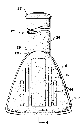
Figure 1 is a side elevational view of a tank
according to the invention. ~.
Figure 2 i8 an end view of the tank of Figure '~ ``b"
1 . ,i~ ,", '.' ',"'; ,`,.. ,,'
Figure 3 is a cross-sectional view of one
module of the tank taken along the lines 3-3 of Figure '.
1. ,'i , ." ~
Figure 4 is a cross sectional vlew along the
lines 4-4 of Figure 2.
~ S'. `
ZO~ O .. , ~,i"~"-
- 9 -
Figure 5 is a cross sectional view along the
llnes 5-5 of Flgure 3. ~'',~.`i~!','`''~:'~'`'"~",'';`'`-'''`',
Flgures 6, 7, 8 and 9 are schematlc slde eleva-
tional vlews of various tanks formed from the modular
tank parts of the present invention.
In the drawings like characters of reference
lndlcate correspondlng parts ln the dlfferent flgures.
DETAILED DESCRIPTION
The tank for mounting in an underground buried
location is indicated generally at 10 and comprises the
maln cyllndrlcal body havlng a perlpheral wall 11 and an
end walls 12 and 13. `:`,!'`,'.`,'.
The perlpheral wall as best shown in Figures 2
and 3 lncludes an upper wall portion 14, a base wall por-
tlon lS and two ~unction portions 16 and 17. The ~unc~
tlon portions interconnect side edges of the base portlon
15 to side edges of the upper portion 14. The base por-
tlon 15 lncludes a flat central part 18 and a palr of ~ ,
outer parts 19 and 20 both of which are inclined upwardly
20, at a shallow angle to the central part 18. This shape ~;,
.: ::, ......
provides a slight curvature effect for the base portion
which increases the resistance of the base portlon
agalnst upward buoyancy forces tending to float the tank
out of the ground, generated by surrounding ground water. ' ~'""'',''~'j
..'.', .' ~
2!3119~0
1 0
' '' ~
The central flat portion 18 allows the tank to sit in a
.........
stable manner on the flat central portion without a
tendency to wobble when the tank is in a storage location
or in transportation.
The upper wall 14 extends from the junction
portions 16 and 17 in a smoothly curved arched shape.
The unique design in the form of an arch, by the nature
of lts structural configuration, was determined to be the
deslgn which would provide maximum support for the weight
of the burial volume (earth cover) over the container.
It has been de~ermined that for the earth cover condi-
tions in question, an arch shape of the common "roman
clrcular form" is the most effective. This design is set
forth with the ob~ective of withstanding a burial depth
ln the range three feet to twelve feet (that is earth
dlstance to the bottom of the tank burlal cavlty).
The roman circular arch configuratlon is pri-
marlly deslgned to withstand unlform compressive loads
wlth llttle or no bendlng stresses accounted for. The
lssue Or bendlng stress is signiflcant slnce ln real llfe
cases a tank would have non uniform coverage in a burial
condition, that ls different loads at different points on
its surface. The bending stress load therefore results
from unequal forces (earth weight) causlng the tank to
: ,,;
20~L19:20 ` ~:;
stress twant to move) in the various directions of the ~ :~
earth coverage (actually opposite to the earth loads). ;
In order to create a tank which can withstand
the multitude of possible load conditions, mathematlcal
calculations have been carried out through a serles of
computerlzed and numerical modelling techni~ues.
The curve function which yielded the best
result to these crlteria was found to be a general
parabolic shape having a function x yn where x ,~ -
represents the wldth of the arch and y represents the
difference from the top of the tank arch downward to a ~-
~olnt intersectlng wlth the wldth x. N represents the
exponent (by curve definition) and was varied between 0.2 ~ '
and 0.3 through a series of successive computer generated ~;
calculatlons. ~: ;
The shape of the upper surface is defined by ~!
the rollowlng table~
COORDINATE TABLE :,
, ~ ~ ,,.
X~CM) Y(CM0 '` ,~`
0 165.00
11.81 163.28 . ~
20.81 159.31
, .. ,. - . .. ... .
~ ~ à
2Q119;20
- . `' .-`
- 12 -
?. ;~
27.56 154.15 : ',~ .3
32.63 149.01 `~
37.13 143.47 ~,~
40.50 138.71
46.69 128.53
52.31 117.73
56.81 107.73
60.75 98.18 `~
64.69 87.80
68.08 78.22
71.44 68.00 `;
74.81 57.14 `;~`
77.63 47.58
80.44 37.57
82.69 29.23
85.50 18.36 `` `
88.34 7.03
90.00 0.00 ~ "-
The above curvature therefore maximizes the
, 20 strength of the wall sha~e. However to yet further lm~
prove the wall shape, rlbs 22 are provlded whlch extend
: around the periphery as an upstanding band. Between each
rlb and the next ad~acent rib ls a recess 23 as best
shown ln Fl~ure 4 80 that the thickness of the materlal
2011~
- 13 ~ .S,
formlng the container ls substantially less than the
dlfference ln helght between the rlbs and the recesses.
The tank shown in Figures 1, 2 and 3 ls formed ~i ~
from two separate portions with a dividing line indicated `~ ~i"
at 24. In the arrangement of Flgure 1 there are two
separate portlons one formlng the ma~or part of the
container on the left hand slde of the line 24 and the
other formlng a smaller part of the container on a right `
hand side of the line 24.
The completed tank lncludes an access openlng ;
generally indicated at 25 defined by a vertical clrcular
cyllndrical wall 26 whlch has a cover 27. As shown ln `~
Figure 3 the clrcular cylindrical wall includes a bottom
portion 28 which connects to a separately molded exten-
sion portion shown in Figures 1 and 2 which presses over
the bottom portion 28 and is attached thereto by fasten~
ers 29. The bottom portion 28 ls lntegrally molded with m Yi~;
the tank modules. The extension portlon ls a separate
element the length of which ls selected in dependence ~ ,
upon the depth of burial of the ~ank. The cover 27 is
again a separately molded part which fastens over the
upper end and readlly removable for access.
It will be noted that the dlvlding llne 24 ex- ~ '
tends also through ~he access openlng. Thus one half of
~ , ~ ",, .
ZOil19;~0 - ;- ~
- 14 -
'''"' '~
the cyllndrical wall ls molded with one part of the tank
and the other half of the cylindrical wall is molded with ;
the other part of the tank. ,."~ ,. ~"~
Turning now to Figure 3, both of the tank mod~
ules are molded in the form of a substantially closed
container having two ends. Thus the left hand tank mod~
ule has one end 12 and the other end 30 shown in most ~`
detall ln Figures 3 and 5. The other tank module has one
end 13 and the other end 31. The ends 30 and 31 as best
seen in Figure 5 are integrally molded with the remainder
of the tank so that they are directly and integrally con- ;~
nected to the perlpheral wall of the tank. Thus the end
walls 30 and 31 cannot pull away from the wall of the
tank should the wall in any way distort so that the end
walls act as a perfect seal of one tank module from the
next tank module. In addition the direct connection of
the end walls to the perlpheral wall Drovides addltlonol
strength of the peripheral wall so that lt ls supported
against any inward distortion caused by external loadinq
, 20 on the wall as discussed previously.
As best shown in Figure 5, both the end walls
includes a flat portion so that the walls can lie in
directly abutting and contac~lng relationshlp. In the
embodiment shown flat wall coveFs the whole of the area
.
'
20~92~
- 15 -
lnwardly of the peripheral wall so that the ~unction line
24 is effectively invisible in the finished tank.
The end wall 30 as shown in Flgure 3 includes a
plurality of scribed clrcles 32 which are formed by in~
dentations ln the mold so that the circles are not cut
through the material but are ~ust deflned visibly in the
material to allow selection of those openings intended to
be cut in the end wall.
Depending upon the intended operation of the
tank, varlous ones of the scribed circles 32 can be cut
through using a suitable cutting implement. The tank
modules can then be connected together by coupling
members shown in Figure 5 and indlcated at 33.
The selection of the openings will be well
known to one skilled in the art based upon conventional
operatlon techniques of septic and holding tank systems.
Each coupling member comprises a first coupllng
part havlng a head 34 and a male screw threaded pro~ect-
lng portlon 35 whlch can extend through the openlng-q cut
at the marked positlons 32. On the outer surface of the
male portlon 35 ls attached a nut 36 so that the head 34
and nut 36 act to clamp a portion of the end walls 30 and
31 together to hold the walls in clamped posltion. As
shown ln ~isure 3, the couplln~ member 33 has a central
2011920
.... . ~ . ~ ~...
'. ~ . :' ' !
- 16 - ~ `-
opening 37 allowlng communication of fluid from one tank
module to the other tank module. Other coupling members
may be free from the central opening as required. Thus -`-
the tank parts can be clamped together at a plurality of ~ `~
positions on the end wall sufficient to hold the end
walls in abuttlng relationship and to prevent twlstlng or
dlstortlng of the tank.
In some cases as described hereinafter, a piped
connection is necessàry between one compartment and the
next. In thls case a pipe 38 can pass through two
allgned openlngs 39 ln the end walls 30 and 31. In order
to provlde an effectlve seal, a sleeve seal 40 is ~ ~ ~
lnserted in the opening so that the pipe passes through a ''~''`'''"''`'i'''`~;`'!~:\'
central bore of the sleeve to prevent any liquld escaplng
lnto the area between the end walls 30 and 31. In thls
case all the coupling members can be of the closed or ,.~"ij~
bllnd type whlch ~revent communlcation fluid between the
two compartments. The open coupling elements are conven-
tlonally available and are known as bulkhead fittings and
are used for providing an exit opening and a connector at
the exit of a conventlonally formed tank. In this case,
however, the bulkhead fittings are used to connect the
two end walls together to form an integral or complete
tank from the tank modules.
- 17 -
,. . .~...........
The end wall 30 as shown ln Figure 3 also ex-
tends up along the bottom portion 28 of the cylindrical
access opening. The end wall forms a dlametrically
extending wall across the access opening. In the orig-
lnally molded part, the upper edge of the end wall ex
tends right up to the top edge of the cyllndrical wall ``
28. However before assembly of the tank parts, the end !~`'; ~, `''i~'~
wall is cut down as lndlcated at 41 so that the bottom
edge of the cut out extends to a posltion below the top ,~
edge 42 of the upper wall part 14. Thus when the end ~`.
walls are connected together, a complete circular open~ng a'ii'9'.'`
is exposed at the upper edge of the bottom portion 28 to
allow access by a person vertlcally downwardly lnto the
clrcular cyllndrlcal area defined by the wall 28. In
additlon the cutout 41 allows the person entering this
access opening to move either to the left or to the right `
as required to enter a chosen one of the tank modules for
servlce or for assembly of the connectlng members pre- ~ 3i~
vlously descrlbed. ; '~
20, In thls way, the slngle access openlng allows ;
access to both tank modules thus avoldlng the necesslty `
of two separate access openlngs.
Turning now to Figure 2, the end face 13 ls
shown which includes a plurality of vertical ribs 44 to `i ;
'~
--`` 20
,, ~'.,,','..,:.,~
- 18
agaln provide a strengthening effect of the end wall. In
the embodlment shown, the end walls are substantlally
vertlcal and parallel but lt will be appreciated that the
end walls can take up any requlred shape provided of
course the abutting or connectlng end walls lnclude the
necessary flat surfaces to provide the necessary connec-
tion and to allow the communication of fluld as required
therebetween.
Turnlng now to Flgures 6 through 9, the tank of
Flgures l through 5 is shown schematically in Figure 8 as
comprising the two separate parts indicated at 45 and 46
connected along the abutting end walls 47 and 48 as pre-
viously described. A portion of the access opening is
indicated at 50. Thus the tank comprises a first module
45 and a second module 46 which are connected together to
form a relatively small tank which ln the example shown
i8 a septlc tank of nominally 1800 litres capacity.
Flgure 6 shows a further tank which comprioes
two of the modules 45 and a second module 51. The module
51 is dlfferent from the module 46 in that lt lncludes
two end walls o~ the connectlng type whlch are thus flat
and lndlcated at 52 and 53. These end walls connect to
the ad~acent end walls of the modules 45. In the example
shown the septlc tank i8 of nominal capacity of 2700
;, , ; ;,:.,
,,~,,"", ~,,...
- 19 -
litres.
The opening 50 as previously described provides
a single complete access opening in the arrangement of
Flgure 6. The part access opening of the left hand mod-
ule 45 can be used to provide merely a small openlng for
vlsual inspection, extraction of materials by suction and ;~
for insertlng the necessary parts of the coupllng members
during inltial assembly.
In Figure 7 is shown a yet further tank con~
struction comprising two of the modules 45 and two of the
modules 51 connected together as previously described.
In this case the tank includes two separate access open
ings 50 each communlcating with two of the modules as
previously described. The tank illustrated has a nominal ` ':':i`,'~"r,
capaclty of 4500 lltres.
In Flgure 9 is lllustrated a yet further tank
Or 3600 lltres nomlnal capaclty which lncludes two of the
modules 45, one of the modules 51 and a yet further mod~
ule 52. The module 52 18 similar to the module 51 ln
!~ 20 thst lt lncludes one half of an access opening 50 and two .~
flat end walls of the coupling type. ~;i ` `';d
It wlll be appreclated that tanks of varylng
capacltles can therefore be manufactured by connectlng
together various ones of the modules 45, 46, 51 and 52.
~ ' .:.. ,~,
' " ~ '~, ~,'' ',;
`- Z0~19Z~
- 20 ~
':.,'~ ,.:'.
Thus to manufacture tanks of the various different capac-
ities, it is necessary only to keep an inventory of four
different types of modules and interconnect these togeth~
er as required. The connecting is carried out as previ-
ously described by cutting out the required ones of the ~-
scribed circles and then insertion of the necessary coup~
ling members. The tanks illustrated are of course of
example only and various different sizes can be manufac-
tured by different combinations as will be appreciated.
The tank formed from the tank modules can be
used for storing various liquids in an underground buried
location. Such tanks are often used for the storing of
clean water or as holding tanks for sewage waste. In
both cases, the tank modules are connected together by a
number Or the bulkhead fittings so that liquid can simply
flow at a number of positions across the end walls from
one compartment to the next compartment so that all com-
partments remain equally filled. It may be necessary to
providb further openings above the intended water line. ,~
The cut down portion of the end walls provided for the
access opening will in addition allow communication of
air rrom one com~artment to the next compartment. `
When used in a septic tank system, the differ~
ent modules provide the separate compartments for the
~"~
2~ 0 ~
- 21 -
.~s,~:. . ...
septic tank system. In a septic tank system there is ~~
generally a septlc compartment ln which the waste materi~
al i8 initially stored to undergo the septlc break down.
In some systems there is only one septic chamber from -
which the liquid is drawn off into an effluent chamber.
The effluent chamber provides a holdlng area so that the
.:;...,., ~;..,-
liquid can be then pumped out or trickled out into a
septic fleld system. In other cases a second septic ~ }
compartment is provided so that the material undergoes a -~
first septlc process, is transferred to a second septic
compartment in which it undergoes a second septic process
and from the second septic compartment is transferred to
the effluent chamber. ,~
The septic compartment must have a certain vol-
ume of alr above the septic liquid. In the septic pro
cess a scum is formed on the upper surface of the liquid
which cooperates with the alr in the septlc process. On
the bottom of the compartment ls a layer of solld materl-
al. Between the scum and the solld materlal ls the
liquld which ls lntended to be removed. As shown ln -~
Flgure 5, therefore, the plpe 38 lncludes an inlet por- -
tion on the left hand slde of the bulkhead which is the
septic compartment. The inlet portion has a mouth at a
depth lower than the coupling portion which passes
.....
. ~. .-, .-,
" ,-, " ,, ;,-.
. .
2~ 2~
~ .,.
~: "~
- 22 ~
~ "'" '~''',' ''-''`
through the seal 40 so that instead of the upper surface `
of the liquid being disturbed by running over into the
effluent chamber, the liquid whlch runs over into the . ~ ..
effluent chamber is drawn from a lower level. ,~
Since various modifications can be made in my i~C~`
invention as herelnabove described, and many apparently -
widely different embodiments of same made within the
spirit and scope of the claims without departing from ..
such spirit and scope, it is intended that all matter
contained in the accompanying specification shall be
interpreted as illustrative only and not in a limiting
sense. ;`~ ``~
,,., ,. .,, "~
,: ~.... ...
"
' ': ` `' i "" " `'
" .
~"~
!. ' ~ ~
'`''`,1'''"':'~
~,