Note: Descriptions are shown in the official language in which they were submitted.
US-205~
.
~01264;;: .
AS~ CLASSIFIER-COOLER-COMBUSTOR
. _
BAC~GROU~D OF T~E INVENTION
~ . _
1. Field of the Invention-
. . _ _ _ _ _ _ .
The invent~on is directed to an ash treatment system and
process for use in the fluidized bed co~bustion of waste
fuels having a high ash contant.
Description:
Fluidized bed reactors are well-known means for genera~ing
heat and, in various forms, -carry out processes such as
drying, roasting, calcining, incineration and heat treatment
of solids with gases in the chemical, metallurgical and
other material processing fields. In the form of fluid bed
boilers, steam is generated for use in driving electric
power generation eguipment, for process heat, for space
heating, or for o~her purposes.
Fluidized bed reactors typically comprise a vessel in which
a bed of particulate solids is present in the reaction
chamber. Sufficient air or other gas i~ introduced into the
vessel below the bed of particulate ~olids in a volume
sufficie~t to achieve a gas velocity that expands or
fluidizes the solids bed, suspending the particulate solid~
of the béd in the flowing air stream and Lmparting to the
individual particles a continuous random motion with the
fluidized bed as a whole resembling a boiling liquid.
Conducting a combustion reaction in a fluidi~ed bed has
important advantages which include attainment of a substan-
tially uniform bed temperature, combustion at relatively low
temperatures and a high heat transfer rate.
- 1 -
US-20~8
Z~ 2~42
Combustion of solid fuels such as coal in a fluid bed
reactor involve~ the gasification of the organic component
of the fuel leaving a residue of solia ash particles. When
burning waste fuels of high ash content in a fluidized bed,
the need to continuously remove from the combusting
fluidized bed the relatively large quantities of red hot ash
becomes a serious problem. In the reactor the very finest
ash particles will be elutriated by the gases flo~ing in the
reactor and will exit through the stack with the exhaust
gases. Ash particles of somewhat larger particle sizes will
become part of the fluidized bed where they improve the
operation of the fluidized bed by retaining heat and con-
tacting an~ igniting fresh fuel particles. The continuous
motion of the ash particles in that fluidized bed brings
about numerous collisions between ash particles in a
softened condition due to the elevated temperature. Under
such conditions, ash agglomerates readily form and these
agglomerates grow to a size such that they are no longer
fluidizable and they tend to descend toward the bottom of
the fluidized bed coming to rest upon the air distribution
plate located beneath the fluidized bed. Such an accumu-
~ation of large ash particles and large ash agglomerates on
the air distribution plate will ultimately cause defluid-
ization of the fluidized bed and subsequent shutdown.
Accordingly, it is well recognized that the accumulation of
excess coarse ash particles and oversized ash agglomerates
mnst be removed from the fluidized bed. As the coarse ash
particles are removed from the bed, it is unavoidable that a
substantial amount of ash fines are also removed. The ash
removed is at a relatively high temperature and represents a
heat loss, if steps are not taken to recover the heat. In
addition, the ash particles removed from the fluidized bed
invaria~ly have associated with them a significant component
o unburned carbon. The unburned carbon represents a loss
US-20~
~2~
of combustio~ efficiency and it would represent a much
sought-after improvement if this carbon could be usefully
burned to enhance reactor operation.
To exemplify the problem, a waste coal or anthracite may
consist of two-thirds ash much of whic:h is in the form of
stone or xock and therefore tends to stay substantially in
the same size range as the feed material to the fluidized
bed boiler. A conventional cooler may be attached to the
ash duct from the combustor with the ash cooled in a stream
of cold air which also strips out the fines for return to
the combustion compartment with the air. Such a unit is
known as a classifier. Alternatively, the ash may be
directed into a second fluidized bed and simply cooled with
air or additional water-cooled tubes in the bed to remove
the heat. Such a unit is a fluidized bed cooler. A third
possibility is to simply have a water-cooled screw trans-
porting the ash and removing the heat. These known devices
have the disadvantage that they have only one functionr
cooling, or at most two, classifying and cooling at the same
time.
As another consideration, fluidized bed boilers operating on
waste fuels have to build up to a high carbon level in the
combusting fluidized bed in order to achieve the proper
combustion temperature which is typically about 1600F. It
will be understood that withdrawing the ash from the
fluidized bed reactor not only removes heat from the
reactor, but also removes unburned carbon which in the
classifier or fluidized bed cooler largely goes ~o waste.
small amount of the carbon may be burned because of the air
present, but the rapidly quenching nature of the cooler or
classifier means that tha reaction rate i5 not maintained
and significant unburned carbon is ejected from the system
in the ash. This, of course, negativaly impacts on overall
boiler and system efficiency.
-- 3 --
--- US-205~
Some of the related prior art i3 indicated bel~w with
comment on the disclosed ~ubject ma~ter.
U.S. Pat. No. 4,700,636, issued October 20, 1987 discloses
an ash classifier device ~or returning ash fines to a
fluidized bed reactor while collecting coarse ash particles
for disposal~ Only minor cooling of the ash particles is
effected. S ~ Ji~
U.S. Pat. No. 4,598,653, issued July 8, 1986, discloses a
combustion system in which fine particles are separated from
coarse particles in a gas stream with entrained fine par-
ticles combusted in an upper combustor and coarse particles
combusted in a lower compaxtment which may be a bubbling
fluid bed combustor. There is provision for returning
uncombusted particles to the ufpper or lower compartment.
~I ~ S ~ f ~ ol 7 (1~
U.S. Pat. No. 4,330tS02, issued May 18, 1982, discloses a
modified fluidized bed reactor having an ash classification
system for separating and returning fines to the reactor
while discharging coarse particles from the reactor.
~ f~ (? ~ f~
U.S. Pat. ~o. 4,301,771, issued November 24, 1981, discloses
a fluidized bed reactor with internal structure for separat-
ing fines from the combustion gases and returning them to
the fluidized bed.
U.S. Pat. No. 3,397 j657, issued August 20, 1968, discloses a
fluidized bed reactor wherein non-inflammable materials are
separated and discharged from the system while the fluidized
medium (fines~ are returned to the reactor.
U~S. Pat. No. 3,001,228, is~ued September 26, 1961, dis-
close~ a fluidized bed system for coating and pelletizing
fusible materials. The process involves coating molten
4 --
. ~ US-205~
~26~2
droplets with solid~ in an upper fluidized bed and collect-
ing the coated pellets in a lower fluidized bed. Excess
particle~ are removed from the lower fluidized bed to a
fluidized bed maintained in an excess particle compartment.
SUMMARY OF THE INVENTION
The a~h treatment system of the invention comprises one or more
vessels or cell~ in which hot ash from a fluidized bed boiler is
received and first classified to separate the fine and coarse ash
fractions. The fine fraction is returned to the boiler and the
coarse fraction is further treated by exposure to large volumes
of air to secure combustion of the ~nburned carbon in the ash.
The coarse ash fraction is thereafter cooled in a fluidi~ed bed
environment with the fluidizing air heated by conta~t with the
ash and the heated air is retained in the process so that the
sensible heat thereof may be utilized.
In a f irst aspect of the invention, an ash treatment ve3sel is
located externally of the fluidized bed reactor or boiler with
which it cooperates. The ash treatment vesscl is connected to
the reactor by at least two conduits; the first for receiving a
hot ash solids feed with a carbon component from the reactor and,
the second, for returning ash fines, some carbon particles, and
hot g~s to the reactor. Air is introduced into the ash vessel at
a lower portion thereo through tuyeres spaced from the bottom of
the ash vessel. The volume and velocity of air introduced by the
tuyere~ is suffi ient to establish a fluidized bed in the lower
portion of said vessel, to burn significant amounts of carbon in
the feed and entrain fines from the solids in the ves~el voluma
above the level of air introduction, while permitting coarse ash
to ~all through an upward flow of air to the bottom of the vessel
where it accumulates helow the level of alr introduction in the
US-2~58 2 ~
fluidized bed. Entrained fines, which include hot ash fine~ and
some small amount of unburned carbon particles, pas~ upward with
hot gas into the conduit which returns the solidc and gas to the
fluidized bed xeactor or boiler. The aix lntroduced into the ash
vessel a3 fluidizing air i~ heated by contact with the fluidiz~d
hot ash and, further, by the co~bustion of carbon particles which
occurs in the vessel. The coarse ash falls into the fluidized
bed at the bottom of the ash vessel where it .is cooled, some ash
dropping out of the fluidized bed into an accumulation volume
provided below the level of air introduction. A~ necessary, the
ash in the accumulation volume is withdrawn from the vessel for
di~posal through a valved conduit which opens into the vessel
bottom.
In a second aspect of the invention, the ash treatment system
comprises a modified ash treatment vessel with one or more
cooperating ash cooling cells. In this embodiment of the
invention, the modified ash treatment vessel carries out the
classification of ash received from the boiler and the combustion
of unburned carbon present in the ash, but effects little or no
cooling of the ash. The cooling function is conducted by one or
more ~luidized bed cooling cells associated with the ash treat-
ment ve3sel. One Such cooling cell adjoins the ash treatment
vessel and i~ in communication with the fluidized bed of the ash
treatment vessel by means of a submerged weir. A~ ash is added
to the ash trea~ment ves3el the level of the fluidized bed
therein tendR to rise, but due to the fluidized nature of the
bed, excess ash material flows past the weir into the fluidized
bed of the adjoining cooling cell~ The ash material in the
fluidized bed of the cooling cell is cooled by the fluidizing
air, while the air is heated in traversing the bed and this hot
air i8 returned to the boiler throuyh a connecting conduit. A
series or train of fluidized bed cooling cells may be connected
to the flr~t cooling cell, each having a submerged weir providing
communication with it~ neighbor. The heated air produced by each
US-2058
26~
cooling cell may be returned to ~he boil~r by a connecting
conduit. Each ~uch cooling cell can reduce the ash temperature
by several hundred degreec (F) so that the ash withdrawn from
the system i8 at a temperature which can be readily handled,
DE~CRIPTION OF THE DRAWINGS
Fig. 1 is a schematic view of the ash treatment sy~tem of the
invention connected to a fluidized bed boiler.
~ig. 2 shows a front sectional view of a further embodiment of
the invention in which the ash treatment vessel is connected to a
plurality o~ ash cooling vessel~.
Fig. 3 is a side sectional view of the embodiment of Fig. 2.
DETAILED DESCRIPTION OF THE INVENTION
Re~erring to Figure 1, there is illustrated a fluidized bed
reactor or boiler 10 connected to the ash treatment system 20 in
accordance with the present invention. The ~luidized bed reactor
10 i~ only partially shown and comprises a sidewall 12 which may
be of water-wall construction in the case of a boiler ana a
bottom wall 13. Within the reactor there is an air distribution
plate 15 whi~h divides the interior space of the reactor into a
windbox 14 below the air distribution plate 15 and a reaction
chamber or combustion volume 17 above the air distribution plate
15. Means (~ot shown) such as a blower is provided for introduc-
ing a large volume of air into the windbox 14. Fluidized bed
material 18, 19 i~ located above the air distribution plate 15
within the combu3tion chamber 17.
- 7 -
US-2058 2~3 ~fi~ .
The ash treatment ~ystem 20 compri-~es an ash vessel 22 located at
a generally lower level than the fluidized bed reactor 10 and an
arrangement of conduits connecti.ng the ash vessel to the
fluidized bed reactor. The ash vessel has a top wall 26, a side
wall 24, while the hottom of the reactor is formed by a slanted
or inclined wall portion 32 which i5 intermediate sidewall 24 and
a centrally located outlet port 33 to which ash disposal conduit
34 is fixad. A plurality of tuyeres 35 pass through inclined
wall portion 32 and are inclined inwardly of the side wall 24 to
direct streams of air into the interior of vessel 2Z. The ash
disposal ronduit 34 has a controlling valve 36 positioned there-
in. A downwardly inclined ash conduit 42 connectn ash exit port
41 in the lower portion of the fluidized vessels bed reactor 10
just above the air distribution plat~ 15 with the ash vessel
through a hot ash inlet port 44. A shut-off valve (not shown)
may be provided in conduit 42. A return condui~ 46 connects the
ash vessel with the fluidized bed reactor through a ga~/solids
outlet port 49 in the top wall or roof 26 of the ash vessel and a
return port 48 in the wall 12 of the fluidized bed reactor.
In operation, the fluidized bed reactor or boiler lQ has within
the combustion chamber 17 a body of particulate matter 18~ 19
which is supported above the air distribution pla~e 15. Air
supplied by a blower to the windbox 14 moves through the perfora-
tions of the air distribution plate 15 into the bed material l8,
19 and expands that bed to a substantial height wi~hin the
combustion cham~er 17. The expanded bed material may not have a
distinct upper surface and there may be a dilute concentration of
Yery fine particles in the upper part of the combustion chamber
17. The fine particles tend to leave the fluidized bed boiler
through the Pxhaust stack fnot shown) of the boiler with the
exhaust gases, but centrifugal means, such as a cyclone, may be
provided in the exhaust system to separate and capture fines for
return to the boiler. With the bed material 18, l9 at elevated
temperature, the air introduced through the air distribution
~S-2058
3LZ~4~
plate 15 ~erves a~ combustion air to burn the c~rbon in the fuel
in the combu~tion chamber 17. The incombustible ash constituent
of the fuel g~nerally xemains as discrete ash particles in the
flu~dized bed, thereby serving a useful f~nction as hot particles
contacting incoming fuel particles and ignlting them, and
further, aiding and maintaining the fluidized condition of the
fluidized bed. However, due to the fact that the fine ash
particles contact each other due to their continuous motion in
the fluidized bed and because they are incandescently hot,
agglomeration of the softened particles cloes occur. As the
particles grow, they are less susceptible to ~luidization and
they tend to descend to a lower level in the fluidized bed just
above the air distribution plate 15. This region of coarser ash
particles is indicated at 18 in Figure 1, while region 19 repre-
sents finer particles located higher in the combustion chamber
17~
The ash exit port 41 in the wall 12 of the fluidized bed reactor
is positioned at a level just above the air distribution plate 15
convenient to the level of the region 1~ of coarse ash particles
in the fluidized bed. The fluidized coarse ash particles move
i~to the inclined ash conduit 42 and so pour into ash vas~el 22
through hot ash inlet port 44.
As shown in Figure 1, for purposes of discussion, the interior of
the ash vessel 22 is shown as being divided into three sections,
Cl, C2 and C3. In fact, there are no boundaries or walls between
the three indicated sections, and the interior volume of the ash
vessel 22 is unobstructed. The coarse ash particles flowing
through hot ash inlet port 44 meet a rising current o air
introduced through the tuyeres 35 in the lower portion of the ash
vessel as well as combustion gases generated in the ash vessel as
will be described. The rising gases within the ash vessel 22
strip the fine ash particles from the introduced ash feed and,
entrained in the gases, the fine particles exit the ash vessel
%~264:;~
US-2058
through the ~as/~olids outlet port 49, traverse the re~urn
condu~t 4Ç and pass into the combu~t~on chamber 17 of the
fluidized bed rea~tor 10 through the xeturn port 48.
The classlfication action, as de~cribed, take~ place approxi-
mately in section C1 of the ash ves~el 20,. In that region the
upflowing air current entrains the fine ash particles as ~t
proceeds toward the return conduit 46 while the coarser ash
particles fall counter-current to the air ~tream ~nto the region
labeled C2, which is designated the carbon combustion reglon. In
region C2 the hot coarsP ash particle~ with their car~on compo-
nent are thoroughly exposed to the rising air stream and rapid
combustion of the carbon proceeds. This combust~on results in an
increase in the gas tPmperature in the region C2 and produces a
substantial volume of hot combustion gases which move with the
air stream through region C1 and return conduit 46 to enter the
fluidized bed reactor at return port 48 ~o as to maintain the
temperature within reaction chamber 17. The carbon-poor coarse
ash particles continue their descent into region C3, designated
the cooling region. I~ region C3 there is a fluidized bed of
relatively coar~e ash particles ~ustained by air flow through the
tuyere~ 35, but in the large central ash disposal conduit 34
there is a buildup of ash particles dropping ou~ of the fluidized
bed in region C3 below the level of tuyere~ 35 to ~orm a quies-
cent body 39 of ash particles in the accumulation volume lying
above valve 36. During the residence time of the ash particles
in the fluidized bed in region C3, they undergo substantial
cooling due to the large volumes of air introduced through the
tuyeres 35. Of course, in traversing the fluidized bed of ash
particle~, the air is heated before its entrance into region C2.
Control of cooled particulate removal is effected by valve 36
which is opened to drop the qu~escent body 39 of ash particles
from the accumulation volume in and above conduit 34 so as to
remove them from the operation by, for example, a water-cooled
-- 10 --
2~2
~-2058
screw 3~ which may effect a further reduction in temper~ture of
the ash disposed as it is conveyed away. Alternatively, the a~h
may alxeady be cool enough (typically le~ than 800F) to enter
the ash conveying mechanis~
Thus it i8 seen that the ash treatment ~y~ste~ 20 rather ~imply
accomplishe3 the nece~sary functions of cla~ification, carbon
burn~up and cooling.
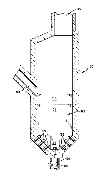
Referring to Figures 2 and 3, there i5 lllustrated another
embodiment of the invention wherein a ~odified ash vessel or
burn-up cell 50 i8 combined with a number of fluidized bed
cooling cells. In this embodiment, the ash vessel 50 carries out
the functions of classifying and carbon burn-up, but does not
significantly cool the ash under treatment. Thus, ash fed into
the fluidized bed 52 of ash vessel 50 is at a temperatur~ in the
range of about 1550 to 1650F. The purpose of the fluidized
cooling cells 60, 70 and 80, then, ~ 3 to achieve a substantial
decrease in the ash temperature. Thus, with three cooling cells
as shown in Figure 3 the temperature of the ash can be reduced to
a level of about 300-400F at which temperature the ash can be
more ea~ily handled by a conventional ash syste~. I~ addition
the air passing through ths ~luidlzed bed of ash in each cell can
be conveyed back to the boiler from each cell at the combined
temperature thus acting as a secondary air heater and recovering
the heat from the a~h and returning it to the boiler.
The ash treatment ve~sel 50 o~ this embodiment has a submerged
weir 54 provided in 'che dividing wall 51 of the ash treatment
vessel at a level just below that of the highest row of tuyeres
35 to provide co~[ununication between the fluidized bed in the ash
ves~el and the fluidized bed of th~ adjacent cooling cell 60. In
turn, the cooling cell 60 has a submerged weir 64 at a low
position of wall 61 within the fluidlzed bed for communication
US-2058 ~ 64~
with a second cooling cell 70~ The cooling cell 70 has it~ own
submexged weir 74 in wall 71 for communication with the last of
the series of cooling cells 80. The cooling cell 80 has a port
88 through which the ash from the fluidizea bed in cooling cell
80 can exit for disposal by operation o~ valve 89. The ash
vessel 50 has a return conduit 46 for return.ing fine ash and hot
gases to the boiler and each of the cooling cells has an exhaust
conduit 66, 76, 86 for returning heated air to the ~oilel-. The
ash vessel 50 is provided with a discharge conduit 56 in the
bottom thereof for withdrawing fluidized bed solids from the
vessel through operation of valve 59 in conduit 56.
While three cooling cells have been shown in this embodiment, the
precise number of cooling cells will depend upon the application
and may be either more or less than that shown. Also, overflow
weirs may be provided instead of the underflow weirs illustrated.
As has been mentioned previously, material is received by the ash
treatment vessel from the boiler combustion chamber at approxi-
mately 1600F. The ash in the burn-up cell 50 is kept at a
combustion temperature of 1550-1650F in order to burn out the
carbon in the ash emerging from the fluid bed combustor. The ash
in the fluidized bed of the burn up cell 50 passes into the first
cooling cell 60 wherein it is cooled by the fluidizing air down
to a temperature in the range of 900-1100F. In the second
cooling cell 70 the temperature of the ash is reduced to the
range of from ~00-700F and in the third cooling cell 80 the
temperature of the ash is reduced to 300-400F.
In this way, the sensible heat that would otherwise have been
lost in di~poQal of the hot ash is regained and typically
decreases the ash temperature from 1600F to 325F representing
approx~mately 5% in boiler efficiency. Reducing the carbon in
the ash from 2.5-3~ on exiting the boiler to les~ than .5% on
exiting the ash cooler also gains over 2.5~ in boiler efficiency
- 12 -
US-2058 ~3 ~2
by increa~ing the combu~ti~n efficiency. Thus~ ovexall, the
combination of ash treatment vessel and coolers ~nable3 an
efficiency galn of approximately 7.5% to be achieved. This is a
significant gain in eficlency when burning poor ~rade fuels such
as anthracite culm or coal collery waste (~gob~) becau~e these
fuels typically have a low calorific heat content in the range o~
2900-3500 Btu/lb~ Even with higher heat content fuels in the
range of 3500-8500 Rtu/lb significant gains in com~ustion ana
overall boiler efficiency can be made.
- 13 -