Language selection

Search

Patent 2013439 Summary

Third-party information liability

Some of the information on this Web page has been provided by external sources. The Government of Canada is not responsible for the accuracy, reliability or currency of the information supplied by external sources. Users wishing to rely upon this information should consult directly with the source of the information. Content provided by external sources is not subject to official languages, privacy and accessibility requirements.

Claims and Abstract availability

Any discrepancies in the text and image of the Claims and Abstract are due to differing posting times. Text of the Claims and Abstract are posted:

  • At the time the application is open to public inspection;
  • At the time of issue of the patent (grant).
(12) Patent: (11) CA 2013439
(54) English Title: CONTAINER ATTACHMENT DEVICE FOR APPLYING PLASTER OR CEMENT TO A TAPE
(54) French Title: DISPOSITIF DE FIXATION DE CONTENANT POUR APPLICATION DE PLATRE OU DE CIMENT SUR UN RUBAN
Status: Term Expired - Post Grant Beyond Limit
Bibliographic Data
(51) International Patent Classification (IPC):
  • B05C 3/132 (2006.01)
  • B05C 11/04 (2006.01)
  • B44C 7/04 (2006.01)
  • E04F 21/00 (2006.01)
(72) Inventors :
  • OVENS, MELVIN L. (Canada)
(73) Owners :
  • MELVIN L. OVENS
  • WAYNE D. KORPA
(71) Applicants :
  • MELVIN L. OVENS (Canada)
  • WAYNE D. KORPA (Canada)
(74) Agent: BORDEN LADNER GERVAIS LLP
(74) Associate agent:
(45) Issued: 1996-10-08
(22) Filed Date: 1990-03-29
(41) Open to Public Inspection: 1991-09-29
Examination requested: 1991-06-20
Availability of licence: N/A
Dedicated to the Public: N/A
(25) Language of filing: English

Patent Cooperation Treaty (PCT): No

(30) Application Priority Data: None

Abstracts

English Abstract


A container attachment device for applying
plaster or cement to a tape passes the tape through a pail
of wet cement or plaster and has a doctor blade to control
the thickness and evenness of the wet cement on the tape.
The device comprises an elongate housing having a clip to
engage the side of a pail or the like adapted to contain
wet cement or the like, the housing extending into the
interior of the pail. An arm extends outwards from a top
portion of the housing above the clip. The arm has a
support adapted to hold a roll of tape. Rollers are
provided on the elongate body for guiding tape from the
roll down to the lower end of the elongate housing in the
pail, and upwards out of the pail, and the doctor blade
ensures that an even thickness of wet cement or the like
is applied to the tape before leaving the pail.


Claims

Note: Claims are shown in the official language in which they were submitted.

- 6 -
THE EMBODIMENTS OF THE INVENTION IN WHICH AN EXCLUSIVE
PROPERTY OR PRIVILEGE IS CLAIMED ARE DEFINED AS FOLLOWS:
1. A container attachment device for applying plaster or
cement to a tape,
which comprises:
an elongate housing having an upper end and a lower
end;
means for removably attaching the housing in an
upright position to the side of a plaster or cement
container with the upper end of the housing
protruding from the top of the container and the
lower end of the housing located towards the base of
the container;
means for rotatably supporting a roll of tape
adjacent the upper end of the housing;
a tape entry opening at the upper end of the housing;
tape support means at the lower end of the housing
for the passage of the tape therearound;
the housing being open at its lower end for exposing
one surface of said tape passing around the tape
support means to plaster or cement in the container
such that the other surface of said tape remains
substantially free of plaster or cement;
a tape exit opening at the upper end of the housing;
and

- 7 -
doctor blade means at the lower end of the housing
for spreading an even layer of plaster or cement on
said one surface of said tape passing around the tape
support means.
2. The device according to claim 1, wherein one elongate
side of the housing comprises a cover which can be
opened to provide access to the interior of the
housing.
3. The device according to claim 1, wherein the tape
support means at the lower end of the housing
comprises a roller.
4. The device according to claim 1, wherein the means
for rotatably supporting a roll of tape adjacent the
upper end of the housing comprises an arm attached to
the housing in proximity to the upper end thereof and
extending transversely of the housing and including
means for rotatably supporting the roll of tape
thereon.
5. The device according to claim 4, wherein the arm is
pivotally connected to the housing and is moveable
between an operative position in which it extends
transversely of the housing and an inoperative
position in which it is located against the housing.
6. The device according to claim 1, wherein the doctor
blade means is adjustable for varying the thickness
of said layer of plaster or cement applied to the
tape.
7. The device according to claim 6, including a hinged
cover for the elongate housing, the hinged cover
containing the adjustable doctor blade means and

- 8 -
permitting insertion of the tape into the housing
when the cover is open.
8. The device according to claim 1, wherein the housing
includes a first roller adjacent the tape entry
opening for receiving tape from the roll of tape;
the tape support means at the lower end of the
housing further comprises a second roller at the
lower end of the elongate housing for guiding tape
after passing over the first roller; and
a third roller at the upper end of the housing
adjacent the tape exit opening for guiding tape after
passing around the second roller for exiting the
housing.

Description

Note: Descriptions are shown in the official language in which they were submitted.


2013439
, 1
CONTAINER ATTACHMENT DEVICE FOR APPLYING PLASTER
OR CEMENT TO A TAPE
INTRODUCTION
The present invention relates to the application
of tape in drywalling and more specifically to a device
for applying cement or plaster to a tape which is then
applied over the joints between adjacent panels.
BACKGROUND OF THE INVENTION
In the past, the application of drywall joint
tape takes place after wet cement or plaster has been
applied to the joint. The tape is then placed over the
wet cement, and in most cases, the tape is dry.
Another method of applying tape is to wet the
tape prior to application. At the present time, a length
of tape is cut and dipped in a container full of water.
This is often inconvenient, because the length of wet tape
can be difficult to handle, and is generally too long,
resulting in a waste of tape.
SUMMARY OF THE INVENTION
It is an aim of the present invention to provide
a device for easily and conveniently applying an even
layer of plaster or cement to a tape, which tape can then
be applied to a dry wall joint.
According to the invention there is provided a
container attachment device for applying plaster or cement
to a tape, which device comprises an elongate housing
having an upper end and a lower end; means for removably
attaching the housing in an upright position to the side
'~C

2013139
of a plaster or cement container with the upper end of the
housing protruding from the top of the container and the
lower end of the housing located towards the base of the
container; means for rotatably supporting a roll of tape
adjacent the upper end of the housing; a tape entry
opening at the upper end of the housing; tape support
means at the lower end of the housing for the passage of
the tape therearound; the housing being open at its lower
end for exposing one surface of a tape passing around the
tape support means to plaster or cement in the container;
a tape exit opening at the upper end of the housing; and
doctor blade means at the lower end of the housing for
spreading an even layer of plaster or cement on a surface
of a tape passing around the tape support means.
One elongate side of the housing may comprise a
cover which can be opened to provide access to the
interior of the housing.
The tape support means at the lower end of the
housing may comprise a roller.
The means for rotatably supporting a roll of
tape adjacent the upper end of the housing may comprise an
arm attached to the housing in proximity to the upper end
thereof and extending transversely of the housing and
including means for rotatably supporting a roll of tape
thereon. The arm may be pivotally connected to the
housing and may be moveable between an operative position
in which it extends transversely of the housing and an
inoperative position in which it is located against the
housing.

_ - 3 -
BRIEF DESCRIPTION OF THE DRAWINGS 2 013 4 3 9
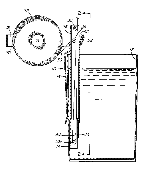
Figure 1 is a sectional side view showing
partially schematically a device for applying plaster or
cement to a tape according to one embodiment of the
present invention.
Figure 2 is a view taken at line 2-2 of
Figure 1.
Figure 3 is a detailed sectional side view of
Figure 1 showing the doctor blade arrangement.
DESCRIPTION OF PREFERRED EMBODIMENT
Referring now to Figure 1, one embodiment of a
drywall tape applicator 10 is shown clipped to a pail or
bucket 12 containing wet plaster, wet cement or other
material to be applied to a tape. The device 10 has a
channel-shaped housing 14 with a clip 16 on the back of
the housing, arranged to clip over the side wall of a pail
12 or other type of container. As can be seen in Figure
1, the housing 14 extends down almost to the bottom of
the pail 12 and also extends above the top of the pail 12.
An arm 18 extends out from the housing 14 above the top of
the pail and has a holder 20 for rotatably supporting a
roll of tape 22 thereon. The arm 18 is pivotally
connected to the housing 14 and is moveable between an
operative position, which is the position shown in Figure
1 and in which it supports a roll of tape, to an
inoperative position, in which it is folded against the
housing 14 with the roll of tape removed therefrom.
The roll of tape 22 is free to rotate on the
holder 20 and a clip or the like (not shown) is provided
to prevent the roll of tape coming off the holder 20. A

2013 139
first roller 24 for the tape is positioned in the housing
14 adjacent where the arm 18 is attached. A slot 26 is
provided in the back of the housing so the tape can pass
through the housing over the roller 24 and downwards to a
bottom roller 28 almost at the lower end of the housing 14
so that it is located in the wet cement in the pail 12.
The tape 30 passes over the first roller 24 down over the
bottom roller 28 and then comes up to a third roller 32
which acts as a guide as the tape extends up for exiting
the housing.
A cover plate 36 is provided with a long hinge
38 for enclosing the housing 14, as shown in Figure 2. A
catch 40 permits the cover 36 to be unlatched and swung
open. The cover 36 is opened for manually loading the
tape 30 over the first roller 24 down to the bottom roller
28 and up to the top roller 32.
A guide plate 44 is positioned in the housing
14, as shown in Figure 3, so that the tape 30 passes over
the plate 44 immediately after leaving the bottom roller
28. A doctor blade 46 is shown opposite the guide plate
44, to provide a scraper or doctor for the wet cement on
the tape 30. The doctor blade 46 is L-shaped and
flexible, joined at the top end to the bottom of the cover
36. A wire 48 is connected to the center of the doctor
blade 46 and extends up to a bolt 50 on a top sloping
portion 52 of the cover 36. The bolt has a right angle
bend and is threaded at one end. The head of the bolt 50
is free to move up and down in a slot 54 in the sloping
part on 52. The threaded portion of the bolt 50 passes
through a hole 56 in a flange 50 of the sloping portion
52. A wing nut 60 adjusts the position of the doctor
blade 46.

2013439
_ 5 -
The doctor blade 46 is flexible and springs back
into place when the wing nut is loosened. The space
between the doctor blade 46 and the tape 30 is set to have
an even thickness of cement or plaster thereon before the
tape leaves the pail.
In operation a roll of tape 22 is placed on the
holder 20, the cover plate 36 is swung open on the hinge
38. The tape 30 is fed over the first roller 24 down over
the bottom roller 28 and up over the guide plate 44
passing the first roller 24 and behind the top roller 32.
The cover 36 is closed and the catch 40 ensures that the
cover remains closed. The doctor blade 46 is set for the
required spacing and the device 10 is then placed in a
pail or container 12 filled with wet cement or other
liquid. The tape is pulled up through the wet cement and
may be loaded into a pail or pot located around a user's
waist before being applied to a drywall joint. It has
been found that the tape can be applied to the joint
without the use of a trowel and torn off in appropriate
lengths after having been applied to the joint.
While only preferred embodiments of the
invention have been described herein in detail, the
invention is not limited thereby and modifications can be
made within the scope of the attached claims.

Representative Drawing
A single figure which represents the drawing illustrating the invention.
Administrative Status

2024-08-01:As part of the Next Generation Patents (NGP) transition, the Canadian Patents Database (CPD) now contains a more detailed Event History, which replicates the Event Log of our new back-office solution.

Please note that "Inactive:" events refers to events no longer in use in our new back-office solution.

For a clearer understanding of the status of the application/patent presented on this page, the site Disclaimer , as well as the definitions for Patent , Event History , Maintenance Fee  and Payment History  should be consulted.

Event History

Description Date
Inactive: Expired (new Act pat) 2010-03-29
Inactive: IPC from MCD 2006-03-11
Grant by Issuance 1996-10-08
Application Published (Open to Public Inspection) 1991-09-29
All Requirements for Examination Determined Compliant 1991-06-20
Request for Examination Requirements Determined Compliant 1991-06-20

Abandonment History

There is no abandonment history.

Fee History

Fee Type Anniversary Year Due Date Paid Date
MF (patent, 8th anniv.) - small 1998-03-30 1998-03-24
MF (patent, 9th anniv.) - small 1999-03-29 1999-03-22
MF (patent, 10th anniv.) - small 2000-03-29 2000-03-21
MF (patent, 11th anniv.) - small 2001-03-29 2001-03-06
Reversal of deemed expiry 2003-03-31 2002-02-11
MF (patent, 12th anniv.) - small 2002-03-29 2002-02-11
Reversal of deemed expiry 2003-03-31 2003-03-28
MF (patent, 13th anniv.) - small 2003-03-31 2003-03-28
2004-03-29
MF (patent, 14th anniv.) - small 2004-03-29 2004-03-29
MF (patent, 15th anniv.) - small 2005-03-29 2005-02-11
2005-02-11
2005-10-17
MF (patent, 16th anniv.) - small 2006-03-29 2005-10-17
2006-11-02
MF (patent, 17th anniv.) - small 2007-03-29 2006-11-02
MF (patent, 18th anniv.) - standard 2008-03-31 2007-12-07
MF (patent, 19th anniv.) - standard 2009-03-30 2008-11-13
Owners on Record

Note: Records showing the ownership history in alphabetical order.

Current Owners on Record
MELVIN L. OVENS
WAYNE D. KORPA
Past Owners on Record
None
Past Owners that do not appear in the "Owners on Record" listing will appear in other documentation within the application.
Documents

To view selected files, please enter reCAPTCHA code :


To view images, click a link in the Document Description column. To download the documents, select one or more checkboxes in the first column and then click the "Download Selected in PDF format (Zip Archive)" or the "Download Selected as Single PDF" button.

List of published and non-published patent-specific documents on the CPD .

If you have any difficulty accessing content, you can call the Client Service Centre at 1-866-997-1936 or send them an e-mail at CIPO Client Service Centre.


Document
Description 
Date
(yyyy-mm-dd) 
Number of pages   Size of Image (KB) 
Claims 1996-10-10 3 83
Abstract 1996-10-10 1 25
Cover Page 1996-10-10 1 15
Drawings 1996-10-10 2 45
Representative Drawing 2000-03-07 1 21
Descriptions 1996-10-10 5 190
Fees 2003-03-28 1 41
Fees 2001-03-06 1 35
Fees 1999-03-22 1 42
Fees 2002-02-11 1 36
Fees 1998-03-24 1 42
Fees 2000-03-21 1 35
Fees 2004-03-29 1 39
Fees 2005-02-11 1 37
Fees 2005-10-17 1 35
Fees 2006-11-02 1 34
Fees 1997-01-13 1 41
Fees 1996-03-26 1 44
Fees 1995-03-27 1 39
Fees 1994-03-29 1 33
Fees 1993-02-16 1 30
Fees 1992-03-10 1 28
PCT Correspondence 1996-03-26 1 29
PCT Correspondence 1996-05-16 1 17
PCT Correspondence 1996-07-31 1 38
Courtesy - Office Letter 1991-11-15 1 25
Examiner Requisition 1993-04-13 1 56
Prosecution correspondence 1991-06-20 1 27
Prosecution correspondence 1993-05-03 2 39
Prosecution correspondence 1991-03-29 2 56