Note: Descriptions are shown in the official language in which they were submitted.
13DV-973~ 3 1.~ 2 6
The government has rights in this invention
pursuant to Contract No. F33657-84-C-20~1 awarded by
the Department of Air Force.
F$eld of the Invention
This in~entlon relates to leaf seals for
sealing the space be~ween two membars of a turbo
~achine, and, mor~ particularly, to a l-af saa}
includi~g a spring wh~ch biase~ the 1~ seal in a
-
. ~loced or~sealing po ition:relati~e to the;t~o m~mbers
at all tim~s r0gardle~s of the pre~sur~ di~exential
across the:leaf seal.
~: ~9~Y CS
~ Lea~ seals are com~only e~ployed ~e af~ect a
substantially ~luid-tight ~al betwe~n abutting
struc~ural~ components in a ~turbo ~machine~ or othe~
: ; ~ apparatus whersln~a ~high~pr~ssure area~is: prssent on~
one side~ of~:~th~ struckural coDponents an~ a lcw
pressure~area ls~presen~ on ~he:~opposite slde thereo~
L~af seals:~are typically relatlvely thln, complia~t
; 20 sections whlch are~Pormed~wlth a~bor~ a~apted ~o elid~
:: ; :
~ ~ ~ 3 .~
13DV-9734
along a pin fixed to o~e of the abutking structural
componentsO Where the structural components to be
sealed are annular in shape, as in many compcnents of
turbo machines, se~mented leaf seals are employed,
i.e., r~latively short, arcuate-shaped leaf seals
which abut one another to form an essPntially con-
tinuous annular seal between the structural compo-
nents.
Regard}ess of the particular shape of the
structural components to be ealed, lea~ seals ar~
movable to a closed, sealinq position in which they
engage each structural component and s-al the space
therebetween, and an open position in which at least
one portion of the leaf seals diæengage a ~tructur~l
15 component and allow the passage o~ gases in between
such components. In most applicatior:ls, moYement of
th~ leaf seals along the pin to a closed position is
efP~cted by~ applying a pressure dif~erential across
the s~al, i~ e., relati~rely high pr-ssur~ on one side
o~ the seal and comparatively low pressure on th2
opposite side thereof forces the ~seal~to a clo~ed,
sealed~ po~itlon against sur~aces~o~; the ~ abutting
structural co~ponen~s to prevent the passage of ga~es
thQrebatween.. ~
While leaf seals have ~ound widespread use
in turbo machines, their effectlveness in creat~ny a
fluid-tight seal is wholly depeDdent on the~ presence
9 ~ ~
13DV-9734
-3-
of a suf~ici~nt pressure diffsrential betwesn one sid2o~ the seal and the other. During certain operating
stages of a turbo machine, the difference in fluid
pressure on opposite sides of the }ea~ seals is
r~latively low. Under khese conditions, it is pos-
sible for the leaf seals to unseat from their engage-
ment with the abutting structural components o~ the
t~rbo machin~ and allow leakage therebetween~
A relatively small pressure diferential
across the leaf seals also permits movemen~ or vibra--
tion of the leaf seals with respect to the structural
co~ponents of ~he turbo machine which they contact.
This vibration of the leaf seals, which is caused by
operakion of th~ turbo machine and o~h~r sources,
creates undesirable wear both of th~ lea~ se~ls and
the sur~ace~s of the s~ructural components against
which the leaf seals seat. Such wear not only re~ults
in leakags of gases between the leaf seals and struc
tural co~nponents o~ the turbo machine, but can cause
20 premature ïailure thereo~.
Summa:~y of the Invcntion
It is therefore among the cbje~ive~ of this
imrention to provide: a l~a* ~saal ~or abu~ting or
ad~oining s~ruc~ural co~ponents of an app~ratus such
a8 a turbo machine to prF~vent the leakage o~ gase~
be~ween such components, which ~reates a reliable,
~luid-tight seal in the space betwe~n such structural
l3DV-973~ 3 3 2 ~
-4-
components, which resists leakage o~ yases regard7ess
of the pressure dif~erential applied to the leaf s~al
and whirh resists vibxation or other movement o~ the
leaf seal relative tc the structural components to be
sealed.
~ hese o~jective are accomplished in an
apparatus for sealing the space betwee~ two abutting
or adjoining structural c~mponents, such a the
components of a turbo mach m e, which comprises a leaf
seal and a spring which continuously biases the leaf
s~al to a closed, sealed position relative to the
structural components to be sealed.
This inYention is prodicated upon the
concep~ o~ retaining a lea~ seal in a closed, sealed
position with re~pect to adjoining or abutting struc-
tural comp~onents by the continuous application of a
Iorcs against the leaf seal by a spring o~ other
biacing means. Regardles f the pressure dif~erPn-
tlal across the leaf seal, the spring or other bia~in~
means maintain~ the lea~ seal in a ~lo~ed, se~l~d
position with respect to th~ ad~oi~ing or abutting
~tructural: omponents to bQ sealed.~: ~dditionally,
: foxcing th- :lea~ eal~continuously against the~abu~-
: ting structural components, v~bration or other rela-
ti~e movement betwaen the leaf seal:and æuch struc-
tural components is~ reduced, ~thus l~ssening wear
b~ween such~:parts~ ::
:
;
::
13DV-g73~ ~J ~ .13 ~ ~ 6
-5-
In one presently preferred embodiment, one
o~ ~he s~ructural componen~s mounts one or more pins,
each of which is adapted ~o support a leaf seal. A
bore or other opening is formed in th2 leaf seal to
fit over such mounting pins. ~he leaf seals are
axially movable along such mounting pins between a
closed, sealed position wherein one portion of the
leaf seal engages a first structural co~ponent and
another portion of the lea~ seal engages a second
structural co~ponent to close the space therebetween,
and an open position in which at least one of the
portlons of the leaf seal disengages a structural
component to permit the passage Or gases in the space
therebetween. A biasing means, preferahly in the ~orm
o~ a~ spring, is mounted to one o~ the structural
: ~ . components and engages the leaf seal at a point
intermediate the portions of th~ lea~ seal which
contact the structural co~ponents. The ~pring is
e~fective to force the lea~ seal against each struc-
tural component 50 as ~o maintai~ ~h~ lea~ seal in a
closed, sealed posi~ion at all times. I~ the pr~ssure
di~erential aoross thQ leaf seal de rease3 during
operation o~ the turbo machine,~the spring neverthe~
le58 retains the~ lea~ s~al ~in~ a seal~d~position
r~lative to:th~ structural components to ~prevent any
leakage of gases ~therebetween.~; M dit~ionallyl vibra-
t~on or oth~r relative movem2nt be~ween ~he:leaf seal
~ 2~.3
13DV-9734
and structural components is reduced by the spring
force exerted against the leaf seal~
A variety of springs may be utilized to
force the leaf seal into engagement with the strUc-
~ural components to be sealed. In one embodiment, the
spring is U-shaped having oppo~ed legs which are
blased away from one another. one leg of the U-shaped
-~pring is mounted to the pin which carrie~ the leaf
seal, and the other leg engages the 12a~ ~seal at a
}O point intermediate its ends so as to bi~as or ~orce the
leaf seal into a closed, sealed position against the
structural components.
In an alternative embodiment, the biasing
means for the lea~ seal is a spiral coil spring having
an open center which is ~itted ovex the pin which
mounts each leaf seal. One end of th~ coil spring
engages a structural component and the oppo~ite end
thereoP engages the leaf seal at a poin~ intermediate
: it~ ends. The coil spri~g is initia1ly compressed in
positioning it between the lea~ seal and structural
component, and then elongates to forca the leaf seal
to a closed, sealed position:relati~e to the struc-
~ral co~ponents~
In a still fur~her embodiment, the biasing
: 25 m~ans: is a sinusoidal-shaped spring h~ing opposed
ends and an arcuate section therebetween. The ends of
the sinusoidal-shaped spring are ~ixedly mounted to
: `
:
~ ~'3
13DV-9734
-7-
one of the s~ructural ~o~ponents so that the axcuate
~ction therebetween engage~ the leaf sea1 and fsrces
it i~to a closed, sealed position with re~pect to the
~tructural co~ponents to be sea1ed.
DescriE~ion o~ the Drawinqs
Th~ structure, operation and adYantages of
the pre~ently pr~ferred embodiment o~ this in~ention
will become ~urther apparent upon consideration o~ the
following description, tak~ in conjunction.with the
acco~panying:drawings, wherein.
: Fig. 1 is a schemati~ partial cross sec-
tiona1 view of a portion of a ~urbo machine illu~trat-
ing on~ 1Ocation in which tha lea~ seal and spring o~
. ~is invention can be utilized;
~lg. 2 is. an en1arged c~oss sectional view
o~ a;portion of Fig. 1 iI1ustratins one~embodiment o~
the lea~ s~al and spring horein;
: Fig. 3 is a view si~ilar to Fig. 2 sh~wing
an alternative e~bodimen~ of the spring ~ployed with
the loaf sea1;herein;
Fig. 4 ~ls a view similar to Flgs. 2 and 3
showin~ a:still further embodiment o~ the spring and
loaf saal co~ inatlon of this~invention; and ~
~ Ylg~. 5 is :a:~cross sec~ional vie~ taken
: 25 generally~along lino 5-5 of;Fig. 4.
?JJ ~
13DV~9734
-8-
Detailed Description of ~he Inv~ntion
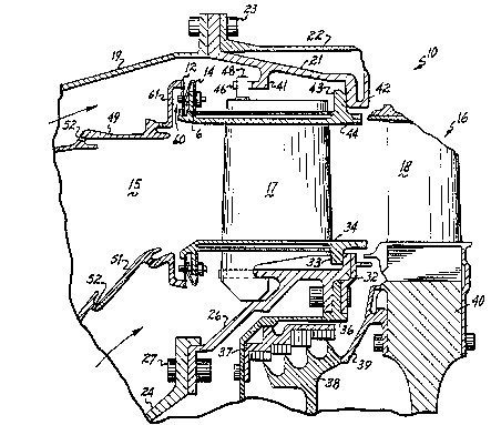
Referring now to Fig. 1, a fragmentary
seictional view of a turbo machine 10 is shown ~or the
purpose of illustrating one environment in which the
segmented leaf seal 12 and spring 14 o~ this invention
can be ~ployed. The detailed construction of the
turbo machine 10 fo~ms no part of.this invention per
se and is thus not discussed in d-tail herein.
Refexence should be made to UOS. Paten~ No. 4,1~6~405,
as6igned to -the same assignee as this invention, for a
d~tail~d discussion of the turbo machine 10, the
disclosure of which is incorporated by reference in
its entir-ty herein.
For purposes o~ the present di~cussion, the l1
turbo machin~ 10 includes a combustor 15 and a high
pressur- turbine 16. The high pressuxe turbin~ 16
i~cludes ~any number o~ stage~, each stage consist~ng
of a row o~ turbine nozzl~s 17 and a~ row:of turbin~ :.
blades 18 altarnately diqposed as is w-ll known in the
: 20 art.
Th~ support st ~ cture for the hiqh pressurei !
tu~bine includes, ~on thQ :radially out-r side,~ a ,,
: . combustor casing 19, an :outeir turbi~ne ring 21 and~a
: turbin- casing 22 whi d are secured together by ~a l;
pluralityl of circumferentially sp w ed bolts 23. on~
: the radially~inner~side of ~he turbine,~ thiere is an
inner ~Go~UStor casinq 24 s-oured to an i~ner turbina
,
:
'~
h~ i 3~2~
13D~-9734
_g_
ring 26 by a plurality of bolt~ 27. On the rear side
of the turbine ring 26, a ~lange 32 extends radially
outwardly to act a~ an axial load stop for the rear
inner rail 33 which projects radially inwardly from
the inner band 34 to fric~ionally engage the flange
32. A bracket 36 is also connected to the inner
turbine ring 26 which, in turn, supports a statio~ary
outer seal 37. The associated rotating inner seal~
member 38 is supported by a bracket 39 extending
forward from the turbine disk 40~
On the radially outer side of the turbine
nozzle 17, the outer turbine ring 21 provides support
by way of an axially extending stop 41 and a U-flange
42-o The U-flange 42 provides support in ~th~ axial
: 15 direation by engaging the rear face o~;th~ rear outer
rail 43 extending radially outwardly ~rom the outer
band 44. An axially extending stop 4~ frictionally
engages an outer lug 48 exte~ding radially outwardly
~rom th~ van~ 14 to provide support in tha circum~er-
ential direction.
Cooling of the system componen~s de~cribed
above~ crea~e~ areas of higher pressura ~and lower
; pressure in the combustor 15 and~tur~ine 16 which mus~
: be: sealed~rom one another. Conventionally, rela~
tively high~ pressure cooling~air ~is circulated around;~:
the annular:combustor 15 between tha combus~or oute~ :
casing 19 and ~the combu~tor ou~-r liner 49.: see
~'J t.3 ~ 7J ~
13DV-9734
~10 -
arrows in Fig. 1. Similarly, the cooling air is
circulated between the inner combustor casing 24 and
the inner combustion liner 51. A portion of the
cooling air passes through holes 52 in the combustor
liner to cool the inner walls thereo~, creating an
area of relatively low pressure, while mcst of ~he air
flows downstream to cool the tu~bine nozzl~s and
shrouds. It is necessary to prevent leakage of air
between the combustor and vane stage interface in
order to obtain the desired flow of cooling air to the
syætem components~
Referring to Figs. 1 and 2, one embodiment
of the sealing device of this invention is positioned
~ . in the space 60 between the vane forward outer rail 61
15 and the combustor rear flange 62, i.e., the structural
components of the turbo machine ~0 lo~ate~ at th~
combustor-vane stage in~erface. A l~a~ seal 64 i~
located in such spac~ 60 and has an inner end 66
~upported within a notch ~7 ~ormed in the vane forward
outer rail 61, and an outer end 68 engageabIe with the
~ombustor rear flange 62. This lea~ seal 64 is
~lidably mounted on a pin 70 connected to the vane
forward outer~rail 61 by a nut~ 72. The lea~ seal 64
is mova~le b~tween a clo~ed, sealed position whereln
its inner end 66 and outer end 68 engage the outer
rall ~1 and rear flange 62, respec~ively, as shown in
Figs~ 1 and 2, and an open position in which at least
:
~ f~
13DV~9734
ona of ~he ends 66, 68 of the leaf seal 64 disengage a
structuxal component.
In the embodiment of Figs. 1 and 2, a
U-shaped spring 74 has a firs~ arm 76 fixedly mounted
on the pin 70 by nut 72 rearwardly of the outer rail
61, and a ~econd arm 78 carried on the pin 7Q on the
forw rd ~ide of ou~er rail 61 in angagement with the
lea~ seal 64. The arms 76, 78 are blasad away ~rom
one another so that in .the position sho~n in Fig. 2,
the second arm 78 of spring 74 urges the leaf spring
64 into engagement with the outer rail 61 and rear
flange~6Z to seal the space 60 therebetween. Prefer-
ablyl the second arm 78 contacts the leaf seal 64 at a
point intermediate its inner ~nd 66 and outer end 68
: 15 so tha~ such ends 66, 68 are positively s~aled against
~he outer rall:61 and rear flange 62.
Referring now to Fig~ 3, the:spring 74 o~
Figs. 1 and 2 is eliminated and replaced:with a spiral
coil,spring 80 for maintaining ~he leaf seal 64 in
po~ition against the outer rail 61 and rear ~lange 62~
The coil spring 80 has an:open center adapted ~o slide
along the~pin 70, a first end 84 which engag@s; ~he
forwar~ face of the outer raiI 61 and a second end 8~
which en~ages~he lea~ seal 64~at a point inte~mediatQ
: ~ :
its inner and outer ends. 66~ 68, resp~ctiYely. The
coil spring 80~ is inièially comprass~d in~ the cours~
0~ pl~CiAg ~ it between:the outer rall 61 and le ~ seal
13DV-9734
-12-
64, and then it extends so tha~ the second end 86urge~ the leaf seal 64 forwardly and into seallng
engagement with the outer rail 61 and rear ~lange 62.
A still further embodiment of this in~ention
is illustrated in Figs. 4 and 5 in which a generally
s~nusoidal-shaped spring 88 is used in place of the
coil spring ZO or U-shaped spring 7~. The sinu-
æoidal-shaped spring 88 ha opposed ends 90 and 92
with a center section 94 formed in a~ arcuate, genero
IO ally sinusoidal shape. The ~spring 88 is fixedly
attached at each end 90, 92 by plns 70 and nu~s 72 so
that khe arouate, center section 94 engages the leaf
sQal 64 at a point intermediate its ends 66, 6~. T~e
center section 94 of spring ~8 is compressed a~ it is
~: 15 positioned betwQen the outer rail 61 and leaf se~l 64
:
so that it urges both ends 66, 68 of the leaf seal 64
into a sealing position against the outer rail 61 and
rear flange S2.
While the invention has been described with
zo re~erence to a preferred e~bodimen~ will be
under~tood by tho~ ~killed in ~he art ~ha~ various
changes may be mad~ and eguivalen~s ~ay ~e substituted
:
for elements thareof wl.thout departing from the~scope
o~ the invention. In addition, many modifications may
be made to~ad~pt ~ particular situation or material to
tha teachings of the inven~ion withou~ d~part~ng fro~
~he essential scope thereof.
. ~
13DV-9734
-13-
For example, the combined l~a~ æeal and
~pring arrangements illu~trated ~n the dra~ings were
shown in the environmen~ of a turbine nozzle and a
turbine machine to create a seal between two struc-
tural elements, i.e., the combustor rear flange andthe vane ~orward outer rail. It should be understood,
however, that the leaf seal and springs disclosed
h~rein could~ be utilized in essentially any applica-
tion in which leaf seals are currently employed.
Additionally, it is contemplated that ~a variety of
diff~rent springs or other biasing means could be
utilized to malntain the leaf seal in a sealed po~i-
.
tion withou~ departing ~rom the scop~ sf this inven-
~, . . .
t~on.
~~I5 ~ There~ore, it 1~ intended that the in~entlon
: not be~limited to th~ part1cular e~bodiment disclosed
as the best mode contemplated for carrylng out this
inventio~, but that the inven~ion will include all
embodiments falling within the scope o~ th~ appended
: 20 ~laim3. ~ :
- :
:
:: : :
.