Language selection

Search

Patent 2014122 Summary

Third-party information liability

Some of the information on this Web page has been provided by external sources. The Government of Canada is not responsible for the accuracy, reliability or currency of the information supplied by external sources. Users wishing to rely upon this information should consult directly with the source of the information. Content provided by external sources is not subject to official languages, privacy and accessibility requirements.

Claims and Abstract availability

Any discrepancies in the text and image of the Claims and Abstract are due to differing posting times. Text of the Claims and Abstract are posted:

  • At the time the application is open to public inspection;
  • At the time of issue of the patent (grant).
(12) Patent Application: (11) CA 2014122
(54) English Title: LAPTOP COMPUTER WITH DETACHABLE INTERFACE CARD
(54) French Title: ORDINATEUR PORTATIF A CARTE D'INTERFACE AMOVIBLE
Status: Deemed Abandoned and Beyond the Period of Reinstatement - Pending Response to Notice of Disregarded Communication
Bibliographic Data
(51) International Patent Classification (IPC):
  • G06C 05/02 (2006.01)
  • G06F 01/16 (2006.01)
(72) Inventors :
  • HO, HERTZ (Taiwan, Province of China)
  • HO, HERTZ (Taiwan, Province of China)
(73) Owners :
  • HERTZ HO
  • HERTZ HO
(71) Applicants :
(74) Agent: ROGERS & SCOTT
(74) Associate agent:
(45) Issued:
(22) Filed Date: 1990-04-06
(41) Open to Public Inspection: 1991-10-06
Examination requested: 1990-04-06
Availability of licence: N/A
Dedicated to the Public: N/A
(25) Language of filing: English

Patent Cooperation Treaty (PCT): No

(30) Application Priority Data: None

Abstracts

English Abstract


ABSTRACT OF THE DISCLOSURE
The laptop computer includes a main computer body
having a rear exposed portion, and a first and a second
rear cover for the rear exposed portion. The first and
second rear covers are detachable and can be
interchangeably connected to the rear exposed portion.
The first rear cover confines an extension space
adjacent to the rear exposed portion when it is
attached. The second rear cover has a size smaller than
the first rear cover and simply covers the rear
exposed portion. The laptop computer further includes
an interface card detachably and optionally attached to
the rear exposed portion and received by the extension
space of the first rear cover.


Claims

Note: Claims are shown in the official language in which they were submitted.

I CLAIM:
1. A laptop computer comprising a main computer body
having a rear exposed portion, and a first rear cover
and a second rear cover for said rear exposed portion,
said first and said second rear covers being
detachably and interchangeably connected to said rear
exposed portion, said first rear cover confining an
extension space adjacent to said rear exposed portion
when said first rear cover is attached to said rear
exposed portion, said second rear cover having a size
smaller than said first rear cover and simply covering
said rear exposed portion when said second rear cover
is attached, said laptop computer further having an
interface card detachably and optionally attached to
said rear exposed portion, said extension space of said
first rear cover receiving said interface card when
said interface card is attached.
2. A laptop computer as claimed in Claim 1, wherein
said interface card has a first side with a vertical
wall projecting therefrom, said vertical wall having
electrical connectors mounted therein.
3. A laptop computer as claimed in Claim 2, wherein
said first rear cover includes an access opening
adjacent to said vertical wall when said first rear
cover is attached to said rear exposed portion, said

access opening permitting electrical connection of said
interface card with external cables.
4. A laptop computer as claimed in Claim 3, wherein
said first rear cover further comprises a plate cover
for said access opening.
5. A laptop computer as claimed in Claim 1, further
comprising a first support arm extending rearward and
then downward from said rear exposed portion and having
a first end removably attached to said rear exposed
portion; a second support arm spaced from said first
support arm and extending rearward and then downward
from said rear exposed portion, said second support arm
having a first end removably attached to said rear
exposed portion and a middle section with an angled
seat flange, said interface card placed between and
removably fastened to said first and said second
support arms and having one end seated on said seat
flange; and a clamping member for clamping said end of
said interface card against said seat flange.

Description

Note: Descriptions are shown in the official language in which they were submitted.


20~122
A LAPTOP COMPUTER WITH D~TACHABLE INTERFACE CARD
BACRGROUND OF THE INVENTION
The invention relates to a laptop computer, more
particularly to a laptop computer having a detachable
interface card.
The Input/Output (I/O) port is a main feature of any
computer, including the laptop computer. However, for
most users who do not use the I/~ port regularly, the
interface card associated with the I/O port is
unnecessary and thus adds bulk to the laptop computer.
SUMMARY OF THE INVENTION
Therefore, the object of this invention is to
provide a laptop computer wit~ a detachable interface
card in order to reduce the size of the same when the
Input/Output port is not in use.
Accordingly, a laptop computer of this invention
comprises a main computer body having a rear exposed
portion, and a first rear cover and a second rear cover
for the rear exposed portion. The first and second rear
covers are detachably and interchangeably connected to
the rear exposed portion. The first rear cover confines
an extension space adjacent to the rear exposed portion
when the first rear cover is attached. The second rear
cover has a size smaller than the first rear cover and
~5 simply covers the rear exposed portion. The laptop
computer further comprises an interface card detacha~ly
and optionally attached to the rear exposed portion and
.

2014~22
received by the extension space of the first rear
cover.
BRIEF DESCRIPTION OP THE DRAWINGS
Other features and advantages of this invention will
become apparent in the following detailed description
of the preferred embodiment with reference to the
accompanying drawings, in which:
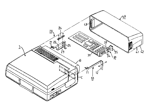
Figure 1 is an exploded view of the preferred
embodiment according to this invention;
Figure 2 is a rear view of a main computer body
according to this invention;
Figure 3 is a perspective view of the preferred
embodiment showing assembly; and
Figure 4 is a side view illustrating the assembly of
a second rear cover of this invention to the main
computer ~ody of Figure 2.
DETAILED DESCRIPTION OF THE PREFERRED EMBODIMENT
Referring to Figure 1, a laptop computer according
to this invention comprises a main computer body 1, a
first support arm 10, a second support arm 20, an
interface card 30, and a first rear cover 40.
Figure 2 is a rear view of the main computer body
according to this invention. The rear exposed portion
of the main computer body 1 has a first and a second
engaging groove 101, 102 oppositely disposed along the
width of the main computer body 1, and a female
electrical connector 103 near a base end of the same. A
,

201 ~ 22 -
storage battery B dispssed at the rear exposed portion
of the main computer body 1 supplies the necessary
power to the laptop computer.
Referring again to Figure 1, the first support arm
10 has a first end 11 removably attached to the first
engaging groove 101. A second end 12 of the same
extends rearward and then downward from the first
.
engaging groove 101. The second support arm 20 has a
first end 21 received by the second e~gaging groove 102
and an angled seat flange 23 formed on a middle section
22. A second end 25 of the second support arm 20
extends rearward and then downward from the second
engaging groove 102. The interface card 30 has a male
electrical connector 31 for electrically communicating
lS with the female electrical connector 103 of the main
computer body 1. A vertical wall 33, which projects
from a first side of the interface card 30, has female
electrical connectors 34 mounted therein. The vertical
wall 33 further includes a transverse end projection 35
screwed to the second end 12 of the first support arm
10. A second side of the interface card 30, opposite
the first side, rests on the seat flange 23 of the
second support arm 20 and is clamped thereat by a
clamping member 24 screwed to the seat flange 23.
Figure 3 shows the interface card 30 attached to the
main computer body 1 and held firmly in place by the
first and second support arms 10, 20.

2 ~ 2 2
Referring once more ~o Figure 1, the first rear
cover 40 is detachably attached to the rear exposed
portion of the main computer body 1. The first rear
cover 40 has a pair of oppositely disposed vertical
S projections 43, which are received by elongated
vertical slots C formed on the periphery of the main
computer bOdy 1. The first rear cover 40 confines an
extension space adjacent to the rear exposed portion.
The interface card 30 is received in the extension
space when the first rear cover 40 is attached to the
rear exposed portion. An access opening 41 is formed on
a side wall of the first rear cover 40 and is adjacent
to the vertical wall 33 of th~e interface card 30. The
access opening 41 permits the electrical connection of
external cables with the female electrical connectors
34 of the interface card 30. A plate cover 42 covers
the access opening 41 when the interface card 30 is not
in use.
If it is desired that the interface card 30 be
detached from the main computer body 1, a second rear
cover 6, as shown in Figure 4, can be used to protect
the rear exposed portion of the main computer body 1.
The second rear cover 6 is similarly detachable from
the main computer body 1, has a size smaller than the
first rear cover 40, and simply covers the rear exposed
portion. The size of the laptop computer of this
invention when the interface card 30 is not attached is
.
~:

therefore smaller and more compact.
While the present invention has been described in
connection with what is considered the most practical
and preferred embodiment, it is understoo~ that this
S invention is not limited to the disclosed embodiment,
but is intended to cover various arrangements included
within the spirit and scope of the broadest
interpretation ~o as to encompass all such
modifications and equivalent arrangements.
~ . . . ~-.

Representative Drawing
A single figure which represents the drawing illustrating the invention.
Administrative Status

2024-08-01:As part of the Next Generation Patents (NGP) transition, the Canadian Patents Database (CPD) now contains a more detailed Event History, which replicates the Event Log of our new back-office solution.

Please note that "Inactive:" events refers to events no longer in use in our new back-office solution.

For a clearer understanding of the status of the application/patent presented on this page, the site Disclaimer , as well as the definitions for Patent , Event History , Maintenance Fee  and Payment History  should be consulted.

Event History

Description Date
Inactive: IPC from MCD 2006-03-11
Time Limit for Reversal Expired 1992-10-06
Application Not Reinstated by Deadline 1992-10-06
Inactive: Adhoc Request Documented 1992-04-06
Deemed Abandoned - Failure to Respond to Maintenance Fee Notice 1992-04-06
Application Published (Open to Public Inspection) 1991-10-06
All Requirements for Examination Determined Compliant 1990-04-06
Request for Examination Requirements Determined Compliant 1990-04-06

Abandonment History

Abandonment Date Reason Reinstatement Date
1992-04-06
Owners on Record

Note: Records showing the ownership history in alphabetical order.

Current Owners on Record
HERTZ HO
HERTZ HO
Past Owners on Record
None
Past Owners that do not appear in the "Owners on Record" listing will appear in other documentation within the application.
Documents

To view selected files, please enter reCAPTCHA code :


To view images, click a link in the Document Description column. To download the documents, select one or more checkboxes in the first column and then click the "Download Selected in PDF format (Zip Archive)" or the "Download Selected as Single PDF" button.

List of published and non-published patent-specific documents on the CPD .

If you have any difficulty accessing content, you can call the Client Service Centre at 1-866-997-1936 or send them an e-mail at CIPO Client Service Centre.


Document
Description 
Date
(yyyy-mm-dd) 
Number of pages   Size of Image (KB) 
Claims 1991-10-05 2 65
Abstract 1991-10-05 1 27
Drawings 1991-10-05 3 89
Descriptions 1991-10-05 5 153
Representative drawing 1999-07-14 1 26