Language selection

Search

Patent 2014206 Summary

Third-party information liability

Some of the information on this Web page has been provided by external sources. The Government of Canada is not responsible for the accuracy, reliability or currency of the information supplied by external sources. Users wishing to rely upon this information should consult directly with the source of the information. Content provided by external sources is not subject to official languages, privacy and accessibility requirements.

Claims and Abstract availability

Any discrepancies in the text and image of the Claims and Abstract are due to differing posting times. Text of the Claims and Abstract are posted:

  • At the time the application is open to public inspection;
  • At the time of issue of the patent (grant).
(12) Patent Application: (11) CA 2014206
(54) English Title: BAT RACK
(54) French Title: RATELIER DE BATTES
Status: Deemed Abandoned and Beyond the Period of Reinstatement - Pending Response to Notice of Disregarded Communication
Bibliographic Data
(51) International Patent Classification (IPC):
  • A47B 81/00 (2006.01)
  • A47F 07/00 (2006.01)
  • A63B 55/10 (2006.01)
  • A63B 71/00 (2006.01)
  • B62B 01/26 (2006.01)
(72) Inventors :
  • FOLEY, KEVIN M. (Canada)
(73) Owners :
  • KEVIN M. FOLEY
(71) Applicants :
  • KEVIN M. FOLEY (Canada)
(74) Agent: MITCHES & CO.
(74) Associate agent:
(45) Issued:
(22) Filed Date: 1990-04-09
(41) Open to Public Inspection: 1991-10-09
Examination requested: 1990-07-03
Availability of licence: N/A
Dedicated to the Public: N/A
(25) Language of filing: English

Patent Cooperation Treaty (PCT): No

(30) Application Priority Data: None

Abstracts

English Abstract


TITLE
BAT RACK
APPLICANT
Kevin Michael Foley
INVENTOR
Kevin Michael FOLEY
ABSTRACT
A portable bat rack is generally shaped in the form of an equilateral triangle
with larger sides of the triangular subtending the front and back of the rack while the
smallest side subtends the bottom of the rack. The rack is closed at bottom and back
and along the sides and carries three laterally disposed shelves, the lowest shelf being
no greater than one half the width the other two shelves, the other two shelves
relatively disposed above the smallest shelf and defining a plurality of bat accomodating
apertures, preferably in an array of two parallel rows, a forward and rearward row.
The rearward row of openings allows bats placed therethrough to rest on the smallest
shelf while the forward row of openings allows the bats to rest on the bottom. The
rack includes a pair of wheels and handle means whereby it may be, on the one hand,
placed stationery on the ground to tip the bats forward and display them in two rows at
different elevations; alternatively pulled by a handle so as to roll over the ground or
allowing the same to be picked up and placed into a trunk of a vehicle with two
handles.


Claims

Note: Claims are shown in the official language in which they were submitted.

The embodiments of the invention in which an exclusive
property and privileges as claimed are defined as follows:
1. A portable rack for housing a plurality of baseball bats in a pre-determined
array comprising opposite vertical triangular side walls, with upper, lower-rear and
lower-forward, apexes, a back and bottom interconnecting and disposed between
respective back and bottom edges of the side walls, the side walls carrying at least
three rigid laterally extending forwardly protruding bat carrying members, each
vertically and spatially disposed one from the other, the upper two bat carryingmembers each defining an array of bat accomodating retaining means, a bottom flat
sheet extending forward from near the lower-rear apex toward the lower-forward apex,
and wheel members mounted in closer proximity to the lower-rear apex than the lower-
forward apex so as to permit the lower-forward apexes, when he rack is in the standing
and used position, to engage the ground and with the wheels to tilt the rack forward.
2. The portable rack as claimed in claim 1 including means for carrying the rack.
3. The portable rack as claimed in claim 1 including handle means near the bottom
thereof and near the upper apex.
4. The portable rack as claimed in claim 1, wherein a handle means is mounted onthe rear surface of the upper back in proximity to the apex.
5. The portable rack as claimed in claim 2 wherein a handle means is mounted on the
rear surface of the upper back in proximity to the apex.
6. The portable rack as claimed in claim 3 wherein a handle means is mounted on the
rear surface of the upper back in proximity to the apex.
7. The portable rack as claimed in claim 1, wherein the upper two rigid bat
carrying member define families of apertures through which bats extend.
8. The rack as claimed in claim 7, wherein the depth of the lowest forwardly
protruding bat carrying member has no aperture and is adapted to act as a rest for bats
disposed through apertures superadjacent thereto so that the rear family of apertures
disposes the bat handle at an elevation higher than that of a forward family of
apertures.

9. The rack as claimed in claim 1, wherein the lower-rear apex is a right angle.
10. The rack as claimed in claim 9, wherein the shortest dimension of the triangular
sides is the bottom margin of the rack.
11. The rack as claimed in claim 1, wherein the upper two carrying members
define orifices through which the bats extend, the orifices arranged at least two rows, a
forward and rearward row, and means for holding the bats in a rearward row at anelevation higher than the bats in a forward row.

Description

Note: Descriptions are shown in the official language in which they were submitted.


BAT RACK
This invention relates to a baseball rack.
In the game of baseball, particularly as a bat boy, it is inconvenient to carry
baseball bats in a duMe bag. ~econdly, the bats then have to be laid out onto the field
so that the players can pick up their bat when in the dugou~.
I have conceived of a moveable baseball rack which can act as a portable storagedevice that can be moved onto the playing field by rolling, and then placed there to act
as a rack displaying that is to be used by the various players.
Particularly, the movable baseball rack has the advantage of allowing a two tiered
display of bats in an array so that they can be easily identified and removed from the
Mck when playing the game of baseball, and alternatively, the rack can be easilytransported as by pulling the same since it has wheels or, lifted by front and back
handle means so that it can be placed into the trunk of a vehicle and maintain the bats
in an orderly fashion.
Specifically, the portable bat rack is generally shaped in the form of an equilateral
triangle with larger sides of the triangular subtending the front and back of the rack
while the smallest side subtends the bottom of the rack. The rack is closed at bottom
and back and along the sides and carries three laterally disposed shelves, the lowest
shelf being no greater than one half the width of the other two shelves, the other two
shelves relatively disposed above the smaUest shelf and defining a plurality of bat
accomodating apertures, preferably in an array of two parallel rows, a forward and
rearward row. The rearward row of openings allows bats placed therethrough to rest
on the smallest shelf while the forward row of openings aUows the bats to rest on the
bottom. The rack includes a pair of wheels and handle means whereby it may be, on
the one hand, placed stationery on the ground to tip the bats forward and display them
~5 in two rows at different elevations; alternatively pulled by a handle so as to roll over
the ground or allowing the same to be picked up and placed into a trunk of a vehicle
with two handled means.
The invention therefore, contemplates a portable rack for housing a plurlaty of
bats in a pre-determined array compAsing opposite vertical side walls, and an
interconnecting back and bottom disposed between respective edges of the sidewalls and
carrying three laterally extending forwardly protruding bat carrying members, each
vertically disposed one from the other, the upper two bat carrying members defining an
array of bat accomodating retaining means. Preferably, the sides are longer vertical
incline sides and a shorter side that forms the bottom, one of the sides forming the
back with a back panel and a bottom panel carrying near their respective apex, wheels,
which cause the bat rack to tip forward slightly when at rest and to display the bats in
an array of two rows, one elevated from the other.
,~
. -,

The invention will now be described by way of example in reference to the
accompanying drawings in which:
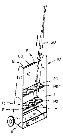
Figure 1 is a perspective view of the rack according to the invention.
Figure 2 is a side elevational view illustrating the two tiers of the rack.
S Figure 3 is a side elevational view showing the rack in transit.
Referring to figure 1, the rack 10 consists of two identical side members 11
generally formed as a triangle with an upper rounded apex, a flat back sheet 12, a flat
bottom sheet 13 closing off the back of the box, and a forward flat lower panel 14.
Between opposite side walls 11, projecting from back panel 12 are two relativelyparallel shelves 16 oriented parallel relatively to each other and a lower shelf 17 of
narrower dimension. The lower shelf 17 is solid while each of the other shelves 16U
and 16L have a plurality of spacially disposed apertures 20 sized to allow a bat 30 to
extend therethrough so as to ~orm two rows of bat holding apertures, a forward row F
and a rearward row R.
As can be clearly seen in figure 2, the rearward row R of bats rests on the lowest
shelf 17 while the forward row of bats F rest on the bottom panel 13 disposing the
forward row of bats at an elevation lower than the rearward row.
Wheels 40 are attached to the rack 10 by means of axle bolt 41 anchored into thebottom rear apex of each of the end triangles. Preferably, the angle between the back
12 and the bottorn 13 forms an acute angle of 75. In this manner, when the rack is in
its resting position shown in figures 1 or 2, the rack tilts slightly forward as more
clearly seen in the side elevational figure 2.
For transport, and now referring to figure 3, the rack is tipped backward and
pulled in the direction of the arrow shown in that figure. In that respect, from the
upper portion of the back of the rack and preferably in the center thereof, is ahorizontal handle bar 60 secured to protruding end member 61 that are affixed to the
rear surface of the back. This handle 60 allows the back to be transported as shown
figure 3 but also, in concert with the forward slotted recess S in vertical lower front
panel 14 to "pick-up" the total rack so that it can be placed into a trunk of a vehicle.
I have found that convenient dimensions for the above is that the vertical triangular
sides of ends 11 should have a length of approximately 41" while the bottom side, a
length of around 15". The wheels 40 have a diameter of approximately 6" while the
bottom shelf 17 is spaced at a distance 6" from the bottom panel 13 and having a width
of approximately 3-" while the other shelves 16 respectively have widths of 7-" and are
disposed from each other and from the bottom 12".
~'
, .
.;

Representative Drawing
A single figure which represents the drawing illustrating the invention.
Administrative Status

2024-08-01:As part of the Next Generation Patents (NGP) transition, the Canadian Patents Database (CPD) now contains a more detailed Event History, which replicates the Event Log of our new back-office solution.

Please note that "Inactive:" events refers to events no longer in use in our new back-office solution.

For a clearer understanding of the status of the application/patent presented on this page, the site Disclaimer , as well as the definitions for Patent , Event History , Maintenance Fee  and Payment History  should be consulted.

Event History

Description Date
Inactive: IPC from MCD 2006-03-11
Inactive: Inventor deleted 2001-08-03
Application Not Reinstated by Deadline 1992-10-09
Time Limit for Reversal Expired 1992-10-09
Inactive: Adhoc Request Documented 1992-04-09
Deemed Abandoned - Failure to Respond to Maintenance Fee Notice 1992-04-09
Application Published (Open to Public Inspection) 1991-10-09
All Requirements for Examination Determined Compliant 1990-07-03
Request for Examination Requirements Determined Compliant 1990-07-03

Abandonment History

Abandonment Date Reason Reinstatement Date
1992-04-09
Owners on Record

Note: Records showing the ownership history in alphabetical order.

Current Owners on Record
KEVIN M. FOLEY
Past Owners on Record
None
Past Owners that do not appear in the "Owners on Record" listing will appear in other documentation within the application.
Documents

To view selected files, please enter reCAPTCHA code :


To view images, click a link in the Document Description column. To download the documents, select one or more checkboxes in the first column and then click the "Download Selected in PDF format (Zip Archive)" or the "Download Selected as Single PDF" button.

List of published and non-published patent-specific documents on the CPD .

If you have any difficulty accessing content, you can call the Client Service Centre at 1-866-997-1936 or send them an e-mail at CIPO Client Service Centre.


Document
Description 
Date
(yyyy-mm-dd) 
Number of pages   Size of Image (KB) 
Drawings 1991-10-08 1 25
Claims 1991-10-08 2 66
Abstract 1991-10-08 1 36
Descriptions 1991-10-08 2 117
Representative drawing 1999-07-13 1 9