Language selection

Search

Patent 2014325 Summary

Third-party information liability

Some of the information on this Web page has been provided by external sources. The Government of Canada is not responsible for the accuracy, reliability or currency of the information supplied by external sources. Users wishing to rely upon this information should consult directly with the source of the information. Content provided by external sources is not subject to official languages, privacy and accessibility requirements.

Claims and Abstract availability

Any discrepancies in the text and image of the Claims and Abstract are due to differing posting times. Text of the Claims and Abstract are posted:

  • At the time the application is open to public inspection;
  • At the time of issue of the patent (grant).
(12) Patent: (11) CA 2014325
(54) English Title: SUPPORT FOR ELECTRIC CABLE
(54) French Title: SUPPORT DE CABLE ELECTRIQUE
Status: Expired and beyond the Period of Reversal
Bibliographic Data
(51) International Patent Classification (IPC):
  • H01B 07/36 (2006.01)
  • G09F 03/20 (2006.01)
(72) Inventors :
  • PIANA, IVANA (Italy)
  • PIANA, SILVANO (Italy)
(73) Owners :
  • GRAFOPLAST S.P.A.
(71) Applicants :
  • GRAFOPLAST S.P.A. (Italy)
(74) Agent: MARKS & CLERK
(74) Associate agent:
(45) Issued: 1998-03-10
(22) Filed Date: 1990-04-10
(41) Open to Public Inspection: 1990-10-14
Examination requested: 1995-07-11
Availability of licence: N/A
Dedicated to the Public: N/A
(25) Language of filing: English

Patent Cooperation Treaty (PCT): No

(30) Application Priority Data:
Application No. Country/Territory Date
12477 A/89 (Italy) 1989-04-14

Abstracts

English Abstract


The closed sleeve support for cable marking having
two or more consecutive and lengthwise opposed partial
notches adapted to spread apart and accommodate cables
having a wide diameter range, due to the elastic opening of
the notches.


French Abstract

Manche fermé d'identification d'un câble. Il est muni d'au moins deux encoches partielles opposées, disposées l'une à la suite de l'autre et de forme longitudinale, qui sont conçues pour séparer et recevoir des câbles de grand diamètre grâce à l'élasticité de leur ouverture.

Claims

Note: Claims are shown in the official language in which they were submitted.

The embodiments of the invention in which an
exclusive property or privilege is claimed are defined as
follows:
1. A closed sleeve support for electric cable marking,
comprising: a closed sleeve, and, at least two lengthwise
opposed partial notches defining a small gap there between
thereby defining intermediate portions connected to each
other or to a semicylinder of the sleeve, so that a large
portion of the inner surface of said sleeve contacts the
surface of the cable to provide stability and to ensure
that as a result of the widening of the notches to the
required extent, said sleeve can be installed on cables
having a wide range of different diameters while the
dimensional requirements only involve the thickness of the
sleeve.
2. A closed sleeve support as claimed in claim 1 wherein
said opposed partial notches are preferably located on said
sleeve opposite the location of the marking code and that
their reciprocal peripheral distance is preferably small so
that the intermediate portions are narrow and can be easily
strained by elastic deformation without generating
deformation of the whole sleeve.
3. A closed sleeve support as claimed in claim 1 wherein
the intermediate portions are connected to the body of the
sleeve by portions having with well defined edges and
angles.
4. A closed sleeve support as claimed in claim 1
wherein the intermediate portions are connected to the
sleeve by portions having curvilineally radiused edges.
5. A closed sleeve support as claimed in claim 1 bearing
-7-

a code identifying the cable according to any of the
commonly adopted marking systems.
6. A closed sleeve support as claimed in claim 5
including a recess formed on said sleeve for receiving code
marking elements.
-8-

Description

Note: Descriptions are shown in the official language in which they were submitted.


20143~
The invention relates to sleeve type supports for
electric wire and cable marking.
Numsrous closed sleeve supports for electric cable
markin~ are already known, as well as lengthwise cut or
C-shaped sleeves.
Particularly well known closed type sleeve supports
are shown in GB-A-960278 and CH-A-607245. Among the
C-shaped sleeves, the solutions according EP-A-01214~4,
US-A-428986 and DE-C-655749 are best known.
All these known solutions essentially differ in their
approach to facilitate installation and improve the
stability of the sleeves on the cable.
Usually, closed sleeve supports have peripheral bends
or internal tabs pressing on the cable to ensure stable
positioning of the support whereas C-shaped sleeves may
have various features to improve their wrapping around the
cable by means of the two open ends of the sleeve.
Furthermore, several cable marking systems are known,
for instance using codes preprinted on the sleeve or
printed on labels glued onto the ~leeve or similar systems. ''
A cable marking system is also known by which ring-shaped
marking elements are introdu¢ed in a recess on the outside
of the support.
This invention concerns a closed sleeve support. A
simple closed sleeve around the cable would obviously
ensure excellent stability if its inside diameter were
slightly smaller than the outside diameter of the cable,
but it would be impossible to fit such a sleeve on the
cable. In praatice, the closed sleeve has therefore an
inside diameter which is much larger than the outside
--1--

201432~
diameter of the cable, while adhssion is achieved by
peripheral accordion folds or elastic inward bent flanges
so as to cause friction between the sleeve and the cable in
order to guarantee a steady positioning.
It follows ! that such sleeves take up much space and
this may cause trouble when marking small sized cables laid
in bundles or near to each other.
Normally, the stability of such accordion folded or
flange fitted sleeves is not very good due to the poor
contact between support and cable which is limited to
horizonatal lines with the further drawback that such
sleeves can be fitted only on cables having the same
diameter as the sleeve or having a slightly different size.
Therefore, the operator in charge of cable marking needs a
large number of sleeves to match the cable diameters.
These problems have led to the adoption of C-shaped
sleeves o~ various types which ensure fair stability and
adjustment to cables in a relatively large diameter range.
The present invention has the object of 1~ ,loving the
stability of closed sleeve supports when installed on the
cables and to make them even more stable than open
C-shaped sleeves. Furthermore, the invention will permit
the same closed sleeve on differently sized cables in a
rather larger diameter range, while ln~ ~zing their
dimensional requirements.
In accordance with the invention there is provided
a closed sleeve for cable marking in which the sleeve has
two or more partial notches which are partially closed and
pointing len~thwise in opposite directions. When these
sleeves are fitted on the cables, their notches will permit
.
-2--

2 Q ~
them to expand until they match the cable diameter, but in
the pxactice, the inner sleeve surface will press against
the cable surface thus ensuring great stability. The
widening of the notches will permit the use of the same
size of sleeve for various cable diameters while
maint~;ning the above mentioned excellent stability.
Furthermore, the dimensional requirements of this
sleeve are limited to its wall thickness only and will
therefore not hinder wire marking, even though the cables
are very small and are laid side by side.
The various features of novelty which characterize
the invention are pointed out with more particularity in
the alaims annexed to and forming a part of this
disclosure. For a better understanding of the invention,
its operating advantages and specific objects attained by
its use, reference should be had to the accompanying
drawings and descriptive matter in which there are
illustrated and described preferred embodiments of the
invention.
IN THE ~RAWINGS
Figure 1 is a top view of a closed sleeve support
provided with two partial notahes, in accordance with the
invention;
Figure 2 is a perspective view of the support
illustrated in figure 1;
Figures 3 and 4 show perspective views of the support
illustrated in figure 2, mounted on cables having different
diameters;
Figure 5 is a top view of a closed sleeve support
featuring three lengthwise opposed alternating notches;

291~32~
Figure 6 is a perspective view of the sleeve
illustrated in fi~ure 5;
Figures 7 and 8 are perspective views of the support
illustrated in figure fi fitted on cables having different
diameters;
Figure 9 shows a perspective view of a sleeve
featuring four lengthwise opposed partial notches.
Figures 10 and 11 are perspective views of a closed
sleeve support similar to that illustrated in figures 1 to
4 featuring two opposed partial notches but having their
inner portions curvilineally radiused to the body of the
sleeve, and,
Figures 12 and 13 are perspective views of the
sleeves of figures 5 to 8, with three opposed partial
notches but having their inner portions curvilineally
radiused onto the body of the sleeve and connected to each
other.
With reference to figures 1 to 4, the closed sleeve
support 1 features, preferably on the side opposite the
marking, two lenethwise opposed, partial notches 2, 3, so :
as to form an intermediate portion 4, one end of which is
connected to one semicylinder and the other end to the
other semicylinder of the sleeve.
The peripheral distance between the partial notches
2, 3 should preferably be small so that the intermediate
portion 4 has a limited width and can be subjected to
elastic deformation without appreciable deformation of the
whole sleeve.
Figures 3 and 4 show that the sleeve 1, when fitted on
the càble 5, is radially expanded due to widening of the
--4--
,., . ' :~

2~32~
notches 2 and 3, but in practice, the whole inner surface
of the sleeve adheres to the outer cable surface, thus
ensuring great stability against axial rotation as well as
~g~inst longitll~in~l movements of the cable. These figures
also show that the sleeve 1 can be fitted on cable 5, as
well as on cable 6, although differently sized, because of
the elastic widening of the notches 2, 3.
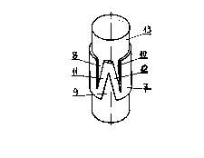
In the embodiments of figures S to 8, the closed
sleeve support 7 has three lenthwise alternately opposed
notches ~, 9, 10 generating two narrow intermediate
portions 11 and 12, the first of which is connected at one
end to one semicylinder of the sleeve, its other end being
connected to the matching end of the second intermediate
portion 12 which, in turn , is connected to the other end
of the other semicylinder of the sleeve.
This embodiment featuring three consecutive partial
notches, enables the same sleeve to fit on quite different
sized cables 13, 14 causing expansion of the notches to a
greater or smaller extent, this flexible expansion range
being greater than for sleeves featuring only ~wo notches.
A further embodiment is illustrated in figure 9 in
which the closed sleeve 15 features four consecutive and
lengthwise alternately opposed partial notches 16, 17, 18,
1~ forming three narrow portions 20, 21, 22 which are
Z-wise connected to each other and to the sleeve halves.
This embodiment extends the possibility of installing the
sleeve on differently sized cables without jeopardizing its
above mentioned great stability on the cable.
The closed sleeve support according to the invention
featuring two or more opposed partial notches thus meets
-5~

2 ~ 2 ~
the stability requirement due to the large contacting
surfaces of the sleeve and cable and to the elastic
deformation of the partial notches permits the same support
to be used for marking cables having different diameters.
In figures 1 to 9, the inner portions 4, 11, 12, 20,
21, and 22 are separated from the sleeve body and from each
other by intersecting lines, generating well defined edges
and angles. In the embodiments of figures 10 to 13 the
inner portions 24, 25 are curvilineally radiused at their
junction to the sleeve and to each other. The approach
adopted in figures 10 to 13 permits less elastic
deformaiton of the sleeve but still ensures excellent
stability on the cable and minimum dimensional
requirements.
The sleeve support featuring partial notches may be
used for known marking elements either preprinted on the
sleeve, or on labels to be glued on the sleeve, or
ring-shpaed marking elements to be introduced into the
recess 23 shown in phantom, in a manner known in the art.
According to the invention, the alosed ~leeve
support can be formed of any material, usually plastic, and
may be obtained by molding or extrusion~ Obviously,
extruded sleeves will require automatic notching and such
sleeves must be aut to length.
The foregoing is a description of a preferred
embodiment of the invention which is given here by way of
example only. The invention is not to be taken as limited
to any of the specific features as described, but
comprehends all such variations thereof as come within the
scope of the appended claims.
--6--

Representative Drawing
A single figure which represents the drawing illustrating the invention.
Administrative Status

2024-08-01:As part of the Next Generation Patents (NGP) transition, the Canadian Patents Database (CPD) now contains a more detailed Event History, which replicates the Event Log of our new back-office solution.

Please note that "Inactive:" events refers to events no longer in use in our new back-office solution.

For a clearer understanding of the status of the application/patent presented on this page, the site Disclaimer , as well as the definitions for Patent , Event History , Maintenance Fee  and Payment History  should be consulted.

Event History

Description Date
Inactive: Reversal of expired status 2012-12-02
Time Limit for Reversal Expired 2010-04-10
Letter Sent 2009-04-14
Appointment of Agent Requirements Determined Compliant 2007-03-30
Inactive: Office letter 2007-03-30
Revocation of Agent Requirements Determined Compliant 2007-03-30
Revocation of Agent Request 2007-03-05
Appointment of Agent Request 2007-03-05
Inactive: IPC from MCD 2006-03-11
Grant by Issuance 1998-03-10
Inactive: Final fee received 1997-11-17
Pre-grant 1997-11-17
Letter Sent 1997-10-14
Notice of Allowance is Issued 1997-10-14
Inactive: Application prosecuted on TS as of Log entry date 1997-10-09
Inactive: Status info is complete as of Log entry date 1997-10-09
Inactive: IPC assigned 1997-08-19
Inactive: IPC removed 1997-08-19
Inactive: First IPC assigned 1997-08-19
Inactive: Approved for allowance (AFA) 1997-08-13
All Requirements for Examination Determined Compliant 1995-07-11
Request for Examination Requirements Determined Compliant 1995-07-11
Application Published (Open to Public Inspection) 1990-10-14

Abandonment History

There is no abandonment history.

Fee History

Fee Type Anniversary Year Due Date Paid Date
Final fee - small 1997-11-17
MF (patent, 8th anniv.) - standard 1998-04-14 1998-03-19
MF (patent, 9th anniv.) - standard 1999-04-12 1999-03-17
MF (patent, 10th anniv.) - standard 2000-04-10 2000-03-16
MF (patent, 11th anniv.) - standard 2001-04-10 2001-03-16
MF (patent, 12th anniv.) - standard 2002-04-10 2002-03-18
MF (patent, 13th anniv.) - standard 2003-04-10 2003-03-24
MF (patent, 14th anniv.) - standard 2004-04-13 2004-03-19
MF (patent, 15th anniv.) - standard 2005-04-11 2005-03-16
MF (patent, 16th anniv.) - standard 2006-04-10 2006-03-06
MF (patent, 17th anniv.) - standard 2007-04-10 2007-03-14
MF (patent, 18th anniv.) - standard 2008-04-10 2008-03-12
Owners on Record

Note: Records showing the ownership history in alphabetical order.

Current Owners on Record
GRAFOPLAST S.P.A.
Past Owners on Record
IVANA PIANA
SILVANO PIANA
Past Owners that do not appear in the "Owners on Record" listing will appear in other documentation within the application.
Documents

To view selected files, please enter reCAPTCHA code :


To view images, click a link in the Document Description column. To download the documents, select one or more checkboxes in the first column and then click the "Download Selected in PDF format (Zip Archive)" or the "Download Selected as Single PDF" button.

List of published and non-published patent-specific documents on the CPD .

If you have any difficulty accessing content, you can call the Client Service Centre at 1-866-997-1936 or send them an e-mail at CIPO Client Service Centre.


Document
Description 
Date
(yyyy-mm-dd) 
Number of pages   Size of Image (KB) 
Drawings 1994-01-19 2 41
Claims 1994-01-19 2 43
Abstract 1994-01-19 1 8
Description 1994-01-19 6 218
Representative drawing 1998-03-05 1 2
Commissioner's Notice - Application Found Allowable 1997-10-13 1 165
Maintenance Fee Notice 2009-05-25 1 170
Correspondence 1997-11-16 1 35
Fees 1998-03-18 1 35
Fees 1998-06-04 1 35
Correspondence 2007-03-04 2 73
Correspondence 2007-03-29 1 13
Correspondence 2007-03-29 1 17
Fees 1997-04-30 1 32
Fees 1997-03-26 1 38
Correspondence 1997-04-22 1 18
Fees 1996-04-09 1 35
Fees 1994-04-04 2 83
Fees 1995-03-30 1 36
Fees 1993-04-07 1 26
Fees 1992-04-06 1 25
Prosecution correspondence 1995-07-10 1 32
Courtesy - Office Letter 1995-07-10 1 52