Note: Descriptions are shown in the official language in which they were submitted.
ADJUSTABLE SHUTTER FOR CONTAINMENT OF
SMALL ELE~TRONICS CO~PONENTS IN TAPE FEEDERS
The present invention is directed to a tape feeder for
feeding small electronics components to a pick ~nd place
machine for placement on a circuit board and, in
particular, to such a tape feeder having an adjustable
shutter for containing the component prior to b~ing picked-
up .
BACKGROUND OF THE INVENTION
In conventional tape feeders for pick and place machines,
the components are typically stored in pockets in reeled
tape. A cover or shutter seals each components in its
pocket. In these typical tape feeders, the shutter that
contains the part during transport of the tape is opened to
15 expose the parts for pick-up by a vacuum tip shortly after
indexing. In high speed applications (on the order of 50
milliseconds for 4 millimeters of index length), the part
becomes unstable and oftentimes changes attitude or
completely flips over in its surrounding pocket after the
20 shutter is opened. This, of course, makes it difficult or
impossible to retrieve the component. ~ 6
To overcome these disadvantages, a~ flat shutter was
developed, as seen in U.S. Patent No. 4,740,136. An access
slot or notch with a width narrower than tha~ of the chip
25 and wider than that of the vacuum tip is formed in the flat
shutter. A vacuum tip fits through the access slot to hold
the component at the proper attitude for pick up. Once the
chip is captivated, the shutter is withdrawn and the chip
is lifted from the pocket. However, this device has the
30 disadvantage that it requires the tip to have a smaller
cross-sectional area tha~ the surface area of the upper
face of the chip. Therefore, extremely small chips cannot
be handled with this device.
Another shutter mechanism is shown in Application Serial
No. 07/27,991, commonly assigned herewith, the contents of
which are incorporated herein by reference. The device
disclosed in this application uses a finger projecting from
the pick-and-place head. The finger engages a shutter
actuating lever, which laterally displaces the shutter to
provide access to the component.
SUMMARY OF rrHE-INvENTIoN
The present invention overcomes the above disadvantages
by providing a shutter that permits the spindle to hold the
components in position for pick-up before the shutter is
withdrawn. The shutter includes a pair of spring bladss
that are opened by the spindle tip to create an access slot
to the pocket that holds the component. Once the component
is firmly held in position by the spindle. The shutter is
withdrawn or displaced in order to remove the component.
This arrangement is advantageous in that it allows the
tip of the pick-up spindle to be slightly larger than the
component, while preventing the component from changing
attitude. Of course, the present invention may be used to
pick-up components that are the same size or larger than
the spindle tip. Another advantage of this arrangement is
that the shutter acts as a guide for the spindle to prevent
any inadvertent movement of the spindle. A further
advantage of this arrangement is tha~ the vacuum may be
switched on prior ~o contacting the tip to the component~
since the shutter maintains the component in a balanced
position and acts as an escapement mechanism that holds the
component stable.
BRIEF DESCRIPTION OF THE DRAWI~NGS
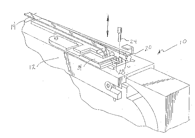
Figure 1 shows a perspective view of the tape feeder
device and shutter in accordance with a first preferred
embodiment of the present invention;
Figure 2 shows a perspective view of the shutter portion
of the device shown in Figure l;
~ L?~ ~5 ~. ~
Figure 3 shows a perspective view of the shutter in
accordance with a second preferred embodim~nt of the
present invention;
Figure 4 shows a perspective view of the shutter shown in
Figure 3, with the shutter withdrawn to permit installation
of a fresh reel of components.
DETAILED DESCRIPTION OF THE PREFERRED EM~ODIMENTS
A first preferred embodiment of the feeder device with
shutt~r mechanism in accordance with the present invention
is shown in Figure 1 and generally designat~d 10.
Throughout the figures, like numerals will be used to
designate like el~ments.
Feeder device 10 includes primary frame 12 for supportiny
reeled tape 14 thereon. The tape includes pockets 16.
Each pocket 16 contains an individual small electronic
component (not shown~ on the order of 20 x 30 mils. up to
1/8 x 1/8 inches. The tape further includes indexing holes
18 which cooperate with indexing pin 20 and an indexing
mechanism (not shown) to present each of the pockets
consecutively to a pick-up mechanism for removal from the
pocket and placement on a circuit board.
In the preferred embodiments, a pick-and-place head is
used to pick-up the components for placement on the circuit
board. The pick-up head includes spindle 22 and vacuum tip
24 connected thereto.
As can be seen more clearly in Figure 2, shutter
mechanism 26 includes sprin~ blades 28 formed of a spring
material, such as stainless steel. The depth of the spring
blades should be sufficien~ that the blades can be angled
to form a tapered arrangement (narrower at the bottom),
thus allowing the spindle tip to more easily spread th~
blades to form an access slot over the component, as will
be explained in more detail below.
~g~
In this first preferred embodiment, the spring blades are
preferably connected via U-shaped connection member 30
which is fitted ~round downwardly extending portion 32 of
pivot bracket 34. T~e spring blades thus extend upwardly
from the ends of the connection member. The pivot bracket
can be manually pivoted upwardly to move the shutter
mechanism out of the way for servicing of the tape or the
like.
In operation, the component supply tape is indexed to
present each pocket consecutively at the pick-up station.
Th~ top cover (not shown) is peeled back so that each
pocket is opened in turn. As the cover is removed, the
shutter mechanism 26 is positioned over the pocket. The
vacuum spindle is then lowered so that the tip spreads the
blades open. Because the blades grip the spindle, they
compensate for any play in the movement of the spindle.
The vacuum is then switched on, while the ~lades maintain
the component at its proper attitude. Alternatively, he
vacuum may be switched on prior to lowering the tip. The
blades are moved axially to disengage from the spindle.
The vacuum tip is then raised to withdraw the component
from the tape. In this way, the device of the present
invention permits the spindle to easily pick-up components
that are smaller in cross-sectional area than the vacuum
tip itself, as clearly shown in Figure 2.
A second preferred embodiment of the feeder device and
shutter mechanism in accordance with the present invention
is shown in Figure 3. This em~odiment of the invention
uses spring blades 28, as in the first preferred
embodiment, connected to one end of flip mechanism 36.
Flip mechanism 36 is preferably bar-shaped, although other
~uitable shapes may be used. The other end of the flip
me~hanism is coupled ~o flat spring 38. The flat spring is
connected at its other end via pin 40 to tension spring 42.
~ ~ ~
n ~
Flip mechanism 36 is operably coupled to pin 44 which
extends from point A to underneath flat spring 38. The pin
has flattened sides so that, when the flip device is
manually pivoted upwardly to permit changing or servicing
of the component supply tape, the flattened sides co-act
with the underside of the flat spring to maintain the flip
device in its upright position.
The entire assembly of flat spring 38, flip mechanism 36
and blades 28 moves. In this way, the shutter can be moved
axially out of the way to permit pick-up of components
having an upper surface area greater than the cross-
sectional area o~ the vacuum tip.
: The foregoing is for illustrative purposes only.
Modifications can be made, particularly with regard to
size, shape and arrangement of parts, within the scope of
the invention as definad by the appended claims. For
;example, it is envisioned that the blades and the connector
member of the shutter mechanism can be coplanar and both
angled so that no upstanding blade portions are necessary.