Language selection

Search

Patent 2014702 Summary

Third-party information liability

Some of the information on this Web page has been provided by external sources. The Government of Canada is not responsible for the accuracy, reliability or currency of the information supplied by external sources. Users wishing to rely upon this information should consult directly with the source of the information. Content provided by external sources is not subject to official languages, privacy and accessibility requirements.

Claims and Abstract availability

Any discrepancies in the text and image of the Claims and Abstract are due to differing posting times. Text of the Claims and Abstract are posted:

  • At the time the application is open to public inspection;
  • At the time of issue of the patent (grant).
(12) Patent: (11) CA 2014702
(54) English Title: COMBINED FIBER OPTIC CONDUITS AND OFFICE PANEL
(54) French Title: CONDUITS A FIBRES OPTIQUES ET PANNEAUX DE BUREAU COMBINES
Status: Expired and beyond the Period of Reversal
Bibliographic Data
(51) International Patent Classification (IPC):
  • E4C 2/00 (2006.01)
  • G2B 6/44 (2006.01)
(72) Inventors :
  • HELLWIG, JOHN (Canada)
(73) Owners :
  • TEKNION FURNITURE SYSTEMS LIMITED
(71) Applicants :
  • TEKNION FURNITURE SYSTEMS LIMITED (Canada)
(74) Agent: BERESKIN & PARR LLP/S.E.N.C.R.L.,S.R.L.
(74) Associate agent:
(45) Issued: 1995-12-12
(22) Filed Date: 1990-04-17
(41) Open to Public Inspection: 1991-10-17
Examination requested: 1993-04-13
Availability of licence: N/A
Dedicated to the Public: N/A
(25) Language of filing: English

Patent Cooperation Treaty (PCT): No

(30) Application Priority Data: None

Abstracts

English Abstract


An office panelling system is advantageously
combined with fiber optic communication cable wherein the
panels of the system are generally open in the center
thereof and the vertical space of the panel is
advantageously used for reducing the curvature of the cable
between panels disposed at an angle. The panels have a
metal framework onto the sides of which cover members are
secured such that the interior of the framework is generally
open. The framework includes a host of distributed passage
ports therethrough for allowing communication cables and the
like to pass through the framework where desired. The fiber
optic communication cable is strung through the frameworks
of the panels and rounds corners between panels disposed at
an angle by using both the vertical and horizontal planes of
the framework to provide a curvature in the cable rounding
the corner between angled panels much greater than the angle
of curvature of the cable if the cable was confined to a
single horizontal plane for rounding the same corner. The
rate of curvature of the cable is important, as in fiber
optic cables light loss is encountered with any corner and
the extent of the light loss increases as the radius of
curvature becomes smaller. It is the general practice that
the rate of curvature should not be less than ten times the
diameter of the cable.


Claims

Note: Claims are shown in the official language in which they were submitted.

- 6 -
THE EMBODIMENTS OF THE INVENTION IN WHICH AN EXCLUSIVE
PROPERTY OR PRIVILEGE IS CLAIMED ARE DEFINED AS FOLLOWS:
1. In combination, an office panelling system and
fiber optic communication cable, said office panelling
system comprising interconnected panels, said panels
interconnecting in a straight line or at angles, including
90 degrees, each panel having a metal framework onto the
sides of which cover members are secured with the interior
of said framework generally available for receiving said
fiber optic cable, said framework including a host of
distributed passage ports therethrough for allowing
communication cables and the like to pass through said
framework where desired; said fiber optic communication
cable being strung through the frameworks of said panels and
rounding corners between panels at an angle by using both
the vertical and horizontal planes of the framework to
provide a curvature in said cable rounding the corner of
said angled panels much greater than an angle of curvature
of the cable if the cable was confined to a single
horizontal plane for rounding the same corner.
2. In combination as claimed in claim 1, wherein at
least two of said panels are generally perpendicular to each
other and said cable rounds the corner therebetween, said
panels having a depth of less than three inches and the
radius of curvature of said cable about said corner is
greater than ten inches.
3. In combination as claimed in claim 1, further
including a plurality of light transmitting cables strung
through said panels with at least several of said light
transmitting cables gently rounding a horizontally abrupt
transition between angled panels by angling the cable with
respect to the vertical and horizontal and using the
vertical space of the panels to smooth the transition.

- 7 -
4. In combination as claimed in claim 3, wherein said
frameworks include a generally open space of at least 20
inches in height.
5. In combination as claimed in claim 1, wherein said
cable is of a diameter between one-half inch and one inch
and the minimum radius of curvature of the cable is greater
than ten times the diameter.
6. In combination an office panelling system and fiber
optic cables, said office panelling system comprising a
number of interconnected panels, each panel having a
framework to which decorative and/or functional panels are
secured either side thereof, said fiber optic cables being
strung through the panels by passing through selected ports
in said frameworks from a host of ports spaced in said
frameworks, said cables using open space within said
frameworks to reduce the rate of required transition for
cables extending between panels generally at an angle, one
to the other.
7. In combination as claimed in claim 6, wherein some
of the panels are disposed at an angle of about 90°.
8. In combination as claimed in claim 7, wherein
generally the full height of the panel is available to
reduce the rate of transition of the cables between panels
disposed at a 90° angle.
9. In combination as claimed in claim 7, wherein at
least some of said cables terminate in a converter device
for converting signals to or from optical to electrical with
said converter secured within a respective panel.
10. In combination as claimed in claim 6, wherein at
least some of said optic cables are of a length greater than

- 8 -
the actual length required and a portion of the open space
within the panels is used to accommodate a large radius
coiled portion of said at least some of said cables
generally corresponding to the length of fibre optic cable
greater than the actual length required.

Description

Note: Descriptions are shown in the official language in which they were submitted.


201470~
WH-7853-89 - 1 -
TITLE: COMBINED FIBER OPTIC CONDUITS
AND OFFICE PANEL
FIELD OF THE INVENTION
The present invention relates to office panelling
systems and in particular to office panelling systems having
a fiber optic cable therein.
BACKGROUND OF THE INVENTION
A number of panelling systems are known which rely
on a framework and have cover members supported either side
of the framework for defining a more pleasing appearance of
the panel. Such a panelling system is disclosed in our
United States Patent 4,535,577.
With the need to transmit data more quickly and
effectively, the use of fiber optic cables has become
common. Electrical signals are converted to impulses of
light which are carried through fine strands of glass or
plastic to another location, with these fine strands of
glass or plastic forming part of the fiber optic cable. At
the receiving end, the light pulses are converted back to
electrical pulses such that the receiving equipment can
interpret these signals in the normal manner. Fiber optic
cables allow many more signals to be transmitted at the same
time through optical fibers that can be transmitted via
copper wire. A further advantage of the optical cables is
that the signals being transmitted are not subject to
interference from other sources, i.e. adjacent power cables,
airport radar, etc. One disadvantage of using fiber optic
cables is with respect to ben~ing and the quality of the
signal decreases with each bend. The generally accepted
rule for bending optical fiber cables is the radius of the
bend must not be less than ten times the outside diameter of
the cable itself. Therefore, if the cable diameter is one
quarter inch, the minimum bending rate is ten times one

Z0~4702
`_.
WH-7853-89 - 2 -
quarter inch which equals two and one-half inches. Often
the cables are much larger and therefore the radius of the
bend must be substantially higher.
Standard approaches for carrying of electrical
cables are not suitable as often the radius of curvature for
the transition from one panel to another panel disposed at
an angle to the first panel is too great if the bend is
maintained in the horizonal plane.
SUMMARY OF THE INVENTION
The present invention recognizes that the
particular panels having a framework and covers on the
exterior thereof have a clear center cavity which can be
effectively used for stringing of fiber optic cables through
the panels. Any radius of curvature of a cable about a
transition point can be reduced in significance by using
both the horizontal and vertical space of the panel to form
the radius of curvature. In order to assist the operator
and provide maximum flexibility, a host of passage ports are
provided in the framework to allow the installer free access
to the interior of the panels and allowing the cable to
effectively utilize this vertical spacing to reduce the
radius of curvature.
BRIEF DESCRIPTION OF THE DRAWINGS
Preferred embodiments of the invention are shown in
the drawings, wherein:
Figure 1 is a perspective view of a number of
interconnected panels assembled in a workstation type
configuration;
Figure 2 is a partial perspective view showing the
transition of a fiber optic cable from one panel to a
connected angle panel;
Figure 3 shows the panel configuration of one with
all the cover members in place; and

~ 3 ~ 2014702
Figure 4 is a perspective view similar to Figure 3
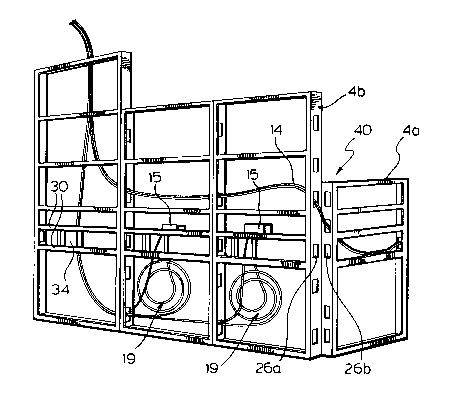
with the covers removed to illustrate how fiber optic cables
can be strung within the interior of the panels.
DETAILED DESCRIPTION OF THE P~FFERRED F~BODIMENTS
The office panelling system, generally shown as 2,
includes a number of interconnected panels 4 which support
the work surface 6. Panels 4b and 4a are arranged in a 90
angle which is quite common in this type of configuration,
not only for stability, but also for convenience in
subdividing space. It can be appreciated that other
arrangements will use other angles and office panelling
systems of this type are fully flexible with respect to the
particular angles between panels. The details for
connecting of these panels and the method of assembling the
panels can be appreciated from our United States Patent
4,535,577.
The panels 4 have cover members 8 releasably
secured thereto which generally conceal the framework and
act as an acoustical barrier against noise transmission. As
shown in our earlier patent, passageways are sometimes used
and in other cases, it may be desired to have glazed panels
or a glazed unit within the framework. Generally at desk
height, access doors 10 are provided which allow for
connection of wiring or other terminals. In this case,
cable 14 is shown as leaving the panel and coming out onto
the work surface 6 and connecting with the information
monitor 12. Cable 14 is connected to the fiber optic supply
cable by means of a converting device which converts the
electrical signals of the information monitor 12 to light
pulses and converts received light pulses to electrical
signals suitable for said information monitor 12. The
panels easily accommodate the securing of these converting
devices 15 within the panel.
As shown in Figure 2 and Figure 4, each panel
includes a rectangular framework 20 comprising vertical

20~4~02
WH-7853-89 _ 4 -
members 22 and horizontal members 24. Within these vertical
members 22 and horizontal members 24 are passage ports 26.
Ports are distributed throughout these members to allow full
use of the interior space of the panels. In Figure 4, it
can be seen that there are a number of horizontal extending
members 30, generally within the height of the lower panel,
and these members define an electrical raceway for
conventional cables running horizontally. This raceway can
be traversed by means of a passageway, shown as 34, which
maintains the electrical conduit, but provides a small
passageway through which cables can be fed. In the case of
fiber optic cables, there is no electrical requirement or
code, as they are harmless. Thus, the fiber optic cables
are not confined to this electrical conbuit extending
horizontally and the cables can pass freely through the
interior cavity of the framework. The host of distributed
passage ports provides full flexibility and the use of the
vertical space, as generally indicated at 40, shows how the
fiber optic cables 14 pass in a generally vertical direction
and the radius of curvature of the cable to accommodate the
transition from the edge of panel 4b to panel 4a results in
the radius being shallow with little loss of light. This is
in contrast to common practice of feeding cables through
limited raceways which are horizontal and would require such
a cable in this system to be fed through horizontally
aligned passage ports. Such an approach limiting the cables
to a horizontal plane, require very rapid transitions of the
cable and thus a small radius of curvature. Small radius of
curvature results in substantial light loss and a number of
such transitions may well render the signal unsuitable for
reproduction.
The panels preferably have a depth of three inches
or less and with a four foot high panel it is easily
possible to satisfactorily round a 90 degree corner with a
radius of curvature of ten inches. Thus a one inch cable
could easily be used. With a four foot section, the lower

2Q14~0Z
-
WH-7853-89 - 5 -
section 5 of the panel is about 20 inches in height which
allows gentle bending of the fiber optic cable to
accommodate transitions between panels or within panels.
This area also acts as a storage area, as indicated in
Figure 2, for storing a large radius coil of an extra length
of fibre optic cable. With this arrangement, the cutting of
the fibre optic cable and creating a new termination, which
is a slow and costly process, is avoided. The large space
available allows the cable to be stored as a large radius
coil 19 (Figure 4) and there is no significant loss of
light. The electrical raceway and communication is
generally there above and will have a number of vertical or
angled ports to allow the fiber optic cables to pass
therethrough.
As can be seen in Figure 4, a host of passage ports
are provided both horizontally and vertically within the
panelling system to allow full use of the vertical space of
the panels when required.
Although various preferred embodiments of the
present invention have been described herein in detail, it
will be appreciated by those skilled in the art, that
variations may be made thereto without departing from the
spirit of the invention or the scope of the appended claims.

Representative Drawing
A single figure which represents the drawing illustrating the invention.
Administrative Status

2024-08-01:As part of the Next Generation Patents (NGP) transition, the Canadian Patents Database (CPD) now contains a more detailed Event History, which replicates the Event Log of our new back-office solution.

Please note that "Inactive:" events refers to events no longer in use in our new back-office solution.

For a clearer understanding of the status of the application/patent presented on this page, the site Disclaimer , as well as the definitions for Patent , Event History , Maintenance Fee  and Payment History  should be consulted.

Event History

Description Date
Time Limit for Reversal Expired 2008-04-17
Letter Sent 2007-04-17
Inactive: IPC from MCD 2006-03-11
Revocation of Agent Requirements Determined Compliant 2000-07-10
Appointment of Agent Requirements Determined Compliant 2000-07-10
Inactive: Office letter 2000-07-10
Inactive: Late MF processed 2000-06-14
Letter Sent 2000-04-17
Letter Sent 1999-06-15
Inactive: Multiple transfers 1999-05-10
Inactive: Adhoc Request Documented 1998-04-17
Letter Sent 1997-04-17
Grant by Issuance 1995-12-12
All Requirements for Examination Determined Compliant 1993-04-13
Request for Examination Requirements Determined Compliant 1993-04-13
Application Published (Open to Public Inspection) 1991-10-17

Abandonment History

There is no abandonment history.

Fee History

Fee Type Anniversary Year Due Date Paid Date
MF (patent, 8th anniv.) - standard 1998-04-17 1998-04-15
MF (patent, 9th anniv.) - standard 1999-04-19 1999-03-15
Registration of a document 1999-05-10
Reversal of deemed expiry 2000-04-17 2000-06-14
MF (patent, 10th anniv.) - standard 2000-04-17 2000-06-14
MF (patent, 11th anniv.) - standard 2001-04-17 2001-04-10
MF (patent, 12th anniv.) - standard 2002-04-17 2002-04-15
MF (patent, 13th anniv.) - standard 2003-04-17 2003-04-10
MF (patent, 14th anniv.) - standard 2004-04-19 2004-03-08
MF (patent, 15th anniv.) - standard 2005-04-18 2005-04-13
MF (patent, 16th anniv.) - standard 2006-04-18 2006-04-12
Owners on Record

Note: Records showing the ownership history in alphabetical order.

Current Owners on Record
TEKNION FURNITURE SYSTEMS LIMITED
Past Owners on Record
JOHN HELLWIG
Past Owners that do not appear in the "Owners on Record" listing will appear in other documentation within the application.
Documents

To view selected files, please enter reCAPTCHA code :


To view images, click a link in the Document Description column (Temporarily unavailable). To download the documents, select one or more checkboxes in the first column and then click the "Download Selected in PDF format (Zip Archive)" or the "Download Selected as Single PDF" button.

List of published and non-published patent-specific documents on the CPD .

If you have any difficulty accessing content, you can call the Client Service Centre at 1-866-997-1936 or send them an e-mail at CIPO Client Service Centre.


Document
Description 
Date
(yyyy-mm-dd) 
Number of pages   Size of Image (KB) 
Abstract 1994-03-31 1 28
Drawings 1994-03-31 2 78
Abstract 1995-12-11 1 35
Description 1994-03-31 5 179
Cover Page 1994-03-31 1 12
Description 1995-12-11 5 207
Claims 1994-03-31 3 78
Claims 1995-12-11 3 91
Cover Page 1995-12-11 1 16
Abstract 1995-12-11 1 35
Drawings 1995-12-11 2 91
Representative drawing 1999-07-08 1 26
Maintenance Fee Notice 2000-05-15 1 178
Late Payment Acknowledgement 2000-06-21 1 171
Maintenance Fee Notice 2007-05-28 1 173
Fees 2003-04-09 1 35
Fees 2001-04-09 1 32
Fees 2002-04-14 1 33
Correspondence 2000-06-13 4 94
Fees 2000-06-13 1 40
Fees 2004-03-07 1 37
Fees 2005-04-12 1 28
Fees 2006-04-11 1 39
Fees 1997-04-14 1 42
Fees 1996-04-03 1 42
Fees 1995-04-12 1 45
Fees 1994-02-21 1 36
Fees 1993-04-18 1 30
Fees 1992-04-02 1 30
Prosecution correspondence 1993-04-12 1 31
PCT Correspondence 1995-09-27 1 37
Prosecution correspondence 1995-05-03 1 35
Courtesy - Office Letter 1993-05-30 1 39
Examiner Requisition 1994-11-06 2 61