Language selection

Search

Patent 2015096 Summary

Third-party information liability

Some of the information on this Web page has been provided by external sources. The Government of Canada is not responsible for the accuracy, reliability or currency of the information supplied by external sources. Users wishing to rely upon this information should consult directly with the source of the information. Content provided by external sources is not subject to official languages, privacy and accessibility requirements.

Claims and Abstract availability

Any discrepancies in the text and image of the Claims and Abstract are due to differing posting times. Text of the Claims and Abstract are posted:

  • At the time the application is open to public inspection;
  • At the time of issue of the patent (grant).
(12) Patent Application: (11) CA 2015096
(54) English Title: METHOD AND APPARATUS FOR FLARING PIPE LINER
(54) French Title: METHODE ET DISPOSITIF D'EVASEMENT DES GAINES DE PROTECTION
Status: Deemed Abandoned and Beyond the Period of Reinstatement - Pending Response to Notice of Disregarded Communication
Bibliographic Data
(51) International Patent Classification (IPC):
  • B29C 53/34 (2006.01)
  • B29C 57/00 (2006.01)
(72) Inventors :
  • DARLING, JAMES RODERICK (Canada)
(73) Owners :
  • DU PONT CANADA INC.
(71) Applicants :
  • DU PONT CANADA INC. (Canada)
(74) Agent: DIMOCK STRATTON LLP
(74) Associate agent:
(45) Issued:
(22) Filed Date: 1990-04-20
(41) Open to Public Inspection: 1991-10-20
Examination requested: 1997-04-18
Availability of licence: N/A
Dedicated to the Public: N/A
(25) Language of filing: English

Patent Cooperation Treaty (PCT): No

(30) Application Priority Data:
Application No. Country/Territory Date
07/346,829 (United States of America) 1989-05-02

Abstracts

English Abstract


ABSTRACT
Method and Apparatus for Flaring
Pipe Liners
An apparatus for flaring the end of a
thermoplastic liner installed in a metal pipe. The
end extends beyond the pipe and the pipe having at
least one flange mounted thereon. The apparatus
comprises a first forming head having a liner
contacting surface disposed at an acute angle
relative to said liner, said surface being adapted
to be pushed against said end to cause said end to
flare outwardly about an acute angle and a second
forming head having a liner contacting surface being
disposed at an angle of at least ninety degrees
relative to said liner. The second forming head
being adapted to be pushed against said end to cause
said end to bend into contact with said flange.


Claims

Note: Claims are shown in the official language in which they were submitted.

Claims:
1. An apparatus for flaring the end of a
thermoplastic liner installed in a metal pipe, said
end extending beyond the pipe and said pipe having
at least one flange mounted thereon, said apparatus
comprising:
a first forming head having a liner contacting
surface disposed at an acute angle relative to said
liner, said surface being adapted to be pushed
against said end to cause said end to flare
outwardly about an acute angle; and
a second forming head having a liner contacting
surface being disposed at an angle of at least
ninety degrees relative to said liner, said second
forming head being adapted to be pushed against said
end to cause said end to bend into contact with said
flange.
2. The apparatus of claim 1 wherein the liner
contacting surface of the first head is disposed at
an angle in the range of about 30 and 80 degrees
relative to said liner.
3. The apparatus of claim 1 wherein the liner
contacting surface of the first head is disposed at
an angle of about 60 degrees relative to the rest of
the liner.
4. The apparatus of claim 1 wherein the liner
contacting surface of the second head is disposed at
an angle of about 90 degrees relative to the rest of
the liner.
5. The apparatus of claim 1 further comprising a
heater plate for heating the forming heads and
wherein each of the forming heads is mounted on a
respective side of said heater plate.
DC9226

6. The apparatus of claim 1 further comprising a
third forming head having a liner contacting surface
which is disposed at an angle of at least ninety
degrees relative to said liner, said third forming
head being adapted to be pushed against said end to
cool said end after it has been contacted with said
second forming head.
7. The apparatus of claim 1 further comprising a
retaining plate adapted to be attached to said
flange for retaining said end in a bent position
after it has been bent by said second forming head.
8. The apparatus of claim 5 wherein said first and
second heads each have mounting means located
thereon for removably mounting said heads onto a
pressure application means for pushing said heads
against said liner.
9. The apparatus of claim 8 wherein said pressure
application means is a hydraulic cylinder assembly.
10. The apparatus of claim 8 wherein said mounting
means is a recess and wherein a projecting portion
on the end of said hydraulic cylinder assembly is
locatable in said recess.
11. A method for flaring the end of a thermoplastic
liner installed in a metal pipe, said end extending
beyond the pipe and said pipe having at least one
flange mounted thereon, said method comprising:
pushing against said end with a first forming
head and applying heat to flare said end outwardly
about an acute angle; and
subsequently pushing against said end with a
second forming head and applying heat to cause said
end to bend into contact with said flange.
DC9226

12. The method of claim 11 further comprising
pushing against said end with a third forming head,
said third forming head being cooled, to cool said
end while maintaining it in a flared position.
13. The method of claim 12 further comprising
bolting a retaining plate onto said flange to
retain said end in a flared position after it has
been cooled by said third forming head.
14. The method of claim 11 wherein each of the
forming heads is mounted on a respective heat
exchange surface of a heater and wherein said first
and second heads each have mounting means located
thereon for removably mounting said heads onto
pressure application means for pressing said heads
against said liner, and wherein the step of pressing
said first head against the end is carried out by
mounting said second head onto said pressure
application means and activating said pressure
application means and wherein the step of pressing
said second head is carried out by mounting said
first head onto said pressure application means and
activating said pressure application means.
DC9226

Description

Note: Descriptions are shown in the official language in which they were submitted.


~5~9~
TITLE
METHOD AND APP~RATUS FOR FLARING PIPE LINERS
BACKG~OUND OF THE INVENTION
This invention relates to a method and apparatus
for flaring an end of a plastic pipe liner installed
inside a pipe.
It is known to line metal pipes with plastic
liners to rehabilitate them and/or to provide
corrosion or chemical resistance. There are many
different methods of lining pipe known in the art.
Canadian patent 1,241,262 (Du Pont Canada Inc.)
discloses a method and apparatus for lining pipe
which involves taking a liner of a larger O.D. than
the IoD~ of the pipe to be lined, reducing the
diameter of the liner with driven rollers and
pulling the liner into the pipe. The pulling force
is then released and the liner is allowed to expand
and fit tightly against the wall of the pipe.
It is known ts weld plastic flanges to the ends
of the liner after installation so that liner
segments may be joined together. However, it is
difficult to do this after the liner has been
inserted into a pipe.
US patents 4,383,966 (Svetlik) and 4,156,~10
Caroll et al) both teach the idea of flaring
thermoplastic pipe ends to form flanges thereon.
However, neither of these patents teach a method of
carrying this out on a thermoplastic liner installed
inside a pipe.
DC9226

2~1~0~
US patent 3,341,894 (Flaming) teaches the idea
of flaring the end of a liner installed inside a
pipe by using a heated plug. It has been found that
using a single plug of the design disclosed in this
patent causes the end of the liner to curl under
itself.
US patent 4,525,319 (Kaspe) discloses a method
and apparatus for forming a flange on a
thermoplastic pipe inside a sleeve. The invention
employs only a single head to move the end of the
liner through an obtuse angle to form a flange.
This head may cause the liner to buckle or it may
cause the liner to curl under itself, which in
either case will create an unsatisfactory flange.
It is desirable to flare the end of the liner
after it has been installed in a pipe to form a
flared end while inhibiting buckling or curling of
the liner under itself.
SUMMARY OF THE INVENTION
Accordingly, the present invention provides an
apparatus for flaring the end of a thermoplastic
liner installed in a metal pipe, said end extending
beyond the pipe and said pipe having at least one
flange mounted thereon, said apparatus comprising:
a first forming head having a liner contacting
surface disposed at an acute angle relative to said
liner, said surface being adapted to be pushed
against said end to cause said end to flare
outwardly about an acute angle; and
a second forming head having a liner contacting
DC9226

~Q~.9~ .
surface being disposed at an angle of at least
ninety degrees relative to said liner, said second
forming head being adapted to be pushed against said
end to cause said end to bend into contact with said
flange.
In another one of its aspects, the invention
provides a method for flaring the end of a
thermoplastic liner installed in a metal pipe, said
end extending beyond the pipe and said pipe having
at least one flange mounted thereon, said method
comprising:
pushing against said end with a first forming
head and applying heat to cause said end to flare
outwardly about an acute angle; and
subsequently pushing against said end with a
second forming head and applying heat to cause said
end to bend into contact with said flange.
It has ~een found that the use of the second
forming head allows the liner to be bent gradually
into contact with the flange so that the liner is
inhibited from buckling or curling under itself.
DESCRIPTION OF THE PREFERRED EMBODIMENTS
Preferred embodiments of the invention will be
further described, by way of illustration only, with
reference to the following drawings, in which:
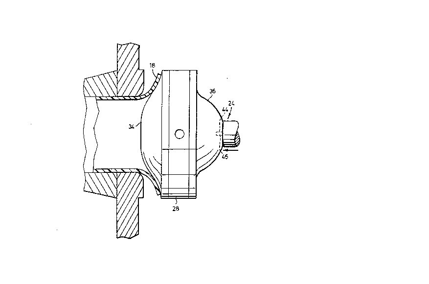
Figure 1 is a side view of a partially assembled
apparatus for flaring pipe;
Figure 2 is a side view in partial cross section
of a flaring head assembly for use with the
apparatus of Figure 1;
DC9226

2 ~
Figure 3 is a side view in partial cross-section
of the apparatus of Figure 1 during a first flaring
stage;
Figure 4 is a side view in partial cross-section
of the apparatus of Figure 1 during a second flaring
stage;
Figure 5 is a side cross-sectional view of the
apparatus of Figure 1 during a third flaring stage;
and
Figure 6 is a side cross-sectional view of the
apparatus of Figure 1 after the third flaring stage.
A partially assembled apparatus for flaring a
thermoplastic liner 10 installed inside a metal pipe
12 having a flange 14 on its end is illustrated in
Figure 1. The liner 10 is held in position in the
pipe by a retractable anchor 16 (indicated in ghost
outlinel, the design of which is known in the art.
The end 18 of the liner extends beyond the end of
the pipe flange 14 by an amount sufficient to cover
the raised face 19 of the flange 14 after flaring. A
flaring unit for flaring the end of this liner is
generally indicated by the number 22. This flaring
unit 22 is pushed against the liner by a hydraulic
cylinder assembly 24. A third flaring head 26 also
forms part of the apparatus and method as will be
discussed later.
Details of the flaring unit 22 may be seen in
Figure 2. This apparatus comprises a heating plate
28 having a handle 30 on the side and a flaring head
34, 36 mounted on each of the circular heat transfer
surfaces 32 thereof. A first flaring head 34 has a
generally convex external
~9226

2 0 1 r~
surface 38. The slope of the peripheral portion 39
of this surface is about 30 degrees. A second
flaring head 36 also has a generally convex external
surface 40. The peripheral portion 42 of this
surface is flat. The flaring heads 34, 36 each have
a recess 44 at the centre thereof for receiving a
projection 4~ of the hydraulic cylinder assembly 24
(see Figure 1).
The projection is located on the end of a
hydraulic cylinder 48, as may be seen in Figure 1.
This cylinder 48 is located in a sleeve 50 and the
annulus between the cylinder and the sleeve is
sealed and filled with hydraulic fluid via an inlet
52. This sleeve 50 is attached to a second flange
54. This second flange 54 is bolted to the pipe
flange 14 so that it is coaxial with the pipe 12.
The third flaring head 26 is of the same design
as the second flaring head 36 described above except
that it has a recess 56 on its rear face 58 instead
of on its front face 60.
The operation of the preferred embodiment of the
invention will now be described with reference to
Figures 3, 4 and 5. As may be seen in Figure 3, the
projection 46 of the hydraulic cylinder assembly 24
is first received in the recess 44 of the second
flaring head 36. The heater 28 is then turned on so
that the flaring heads 34, 36 are heated to a
temperature around the glass transition temperature
of the liner material. The first flaring head 34 is
then pressed against the liner using the hydraulic
cylinder assembly 24 for a suffient amoun~ of time
and at a sufficient pressure so that the peripheral
DC9226

20~50~
portion 39 contacts and flares the liner end 18.
The liner end 18 is thereby flared by about a sixty
degree angle. The first flaring head 36 is then
removed from the liner and the flaring unit is
turned over by turning the handle 30 so that the
second flaring head 36 faces the liner. The
projection 46 of the hydraulic cylinder assembly is
then inserted in the recess 44 of the first flaring
head as may be seen in Figure 4. The second flaring
head 36 is then pressed against the partially flared
end 18 using the hydraulic cylinder assembly 24.
The peripheral flat portion 42 of the head is
pressed for a sufficient amount of time and at a
sufficient pressure to bend the flared end 18 until
it is normal to the rest of the liner and is in
contact with the raised face 19 of the flange 14.
The flaring assembly 22 is then removed from the
liner and is disengaged from the hydraulic cylinder
assembly 24. The third flaring head 26, which has
been chilled in a refrigeration unit, is then
mounted on the hydraulic cylinder assembly 24 by
inserting the projection 46 of the hydraulic
cylinder assembly into the recess 56 on tne rear
face 58 of the head 26. The third flaring head 26
is then pressed against the liner end 18 for a
sufficient amount of time to cool the liner while
maintaining it in the bent shape.
The third head is removed after cooling and, as
may be seen in Figure 6, a retaining plate 62 may be
bolted to the flange 14 to inhibit the liner end
from creeping back to its original unflared
position.
DC9226

2 ~ 3 ~
Modifications to the preferred embodiment may be
made within the scope of the invention as described
and claimed. The periphery of the first head may
be of any design suitable to flare the end of the
liner about an angle in th~ range of about 30 and 80
degrees and most preferably about an angle of around
60 degrees relative to the rest of the liner.
The second head may be of any design suitable to
flare the end of the liner by about an angle of
between 90 and 110 degrees and most preferably about
an angle of around 90 degrees relative to the rest
of the liner.
The preferred,embodiment of the present
invention provides several advantages. The use of
the first two heads allows for gradual forming of
the flared end to avoid buckling or curling under of
the end~ Also, the two heads are mounted on opposed
heated plates of a heater to form a unit that is
easy to use and allows the heads to be quickly and
easily interchanged. The cooled head allows the
flared end to be cooled quickly while it is
maintained in the ~lared position. The use of a
final retaining plate during storage inhibits creep
of the liner back to its original unflared position.
DC9226

Representative Drawing
A single figure which represents the drawing illustrating the invention.
Administrative Status

2024-08-01:As part of the Next Generation Patents (NGP) transition, the Canadian Patents Database (CPD) now contains a more detailed Event History, which replicates the Event Log of our new back-office solution.

Please note that "Inactive:" events refers to events no longer in use in our new back-office solution.

For a clearer understanding of the status of the application/patent presented on this page, the site Disclaimer , as well as the definitions for Patent , Event History , Maintenance Fee  and Payment History  should be consulted.

Event History

Description Date
Inactive: IPC from MCD 2006-03-11
Application Not Reinstated by Deadline 2001-04-20
Time Limit for Reversal Expired 2001-04-20
Deemed Abandoned - Conditions for Grant Determined Not Compliant 2000-05-23
Deemed Abandoned - Failure to Respond to Maintenance Fee Notice 2000-04-20
Notice of Allowance is Issued 1999-11-22
Letter Sent 1999-11-22
Notice of Allowance is Issued 1999-11-22
Inactive: Approved for allowance (AFA) 1999-10-06
Revocation of Agent Requirements Determined Compliant 1999-03-11
Appointment of Agent Requirements Determined Compliant 1999-03-11
Revocation of Agent Request 1999-01-27
Appointment of Agent Request 1999-01-27
Appointment of Agent Request 1999-01-22
Revocation of Agent Request 1999-01-22
Revocation of Agent Request 1998-12-08
Appointment of Agent Request 1998-12-08
Inactive: Delete abandonment 1997-12-08
Letter Sent 1997-12-08
Inactive: Status info is complete as of Log entry date 1997-12-08
Inactive: Application prosecuted on TS as of Log entry date 1997-12-08
Inactive: Office letter 1997-07-18
Reinstatement Requirements Deemed Compliant for All Abandonment Reasons 1997-06-17
Inactive: Abandon-RFE+Late fee unpaid-Correspondence sent 1997-04-21
Deemed Abandoned - Failure to Respond to Maintenance Fee Notice 1997-04-21
All Requirements for Examination Determined Compliant 1997-04-18
Request for Examination Requirements Determined Compliant 1997-04-18
Application Published (Open to Public Inspection) 1991-10-20

Abandonment History

Abandonment Date Reason Reinstatement Date
2000-05-23
2000-04-20
1997-04-21

Maintenance Fee

The last payment was received on 1999-04-01

Note : If the full payment has not been received on or before the date indicated, a further fee may be required which may be one of the following

  • the reinstatement fee;
  • the late payment fee; or
  • additional fee to reverse deemed expiry.

Please refer to the CIPO Patent Fees web page to see all current fee amounts.

Fee History

Fee Type Anniversary Year Due Date Paid Date
Request for examination - standard 1997-04-18
MF (application, 7th anniv.) - standard 07 1997-04-21 1997-06-17
Reinstatement 1997-06-17
MF (application, 8th anniv.) - standard 08 1998-04-20 1998-03-10
MF (application, 9th anniv.) - standard 09 1999-04-20 1999-04-01
Owners on Record

Note: Records showing the ownership history in alphabetical order.

Current Owners on Record
DU PONT CANADA INC.
Past Owners on Record
JAMES RODERICK DARLING
Past Owners that do not appear in the "Owners on Record" listing will appear in other documentation within the application.
Documents

To view selected files, please enter reCAPTCHA code :


To view images, click a link in the Document Description column. To download the documents, select one or more checkboxes in the first column and then click the "Download Selected in PDF format (Zip Archive)" or the "Download Selected as Single PDF" button.

List of published and non-published patent-specific documents on the CPD .

If you have any difficulty accessing content, you can call the Client Service Centre at 1-866-997-1936 or send them an e-mail at CIPO Client Service Centre.


Document
Description 
Date
(yyyy-mm-dd) 
Number of pages   Size of Image (KB) 
Representative drawing 1999-07-12 1 14
Abstract 1994-02-19 1 19
Drawings 1994-02-19 3 82
Description 1994-02-19 7 221
Claims 1994-02-19 3 93
Cover Page 1994-02-19 1 14
Notice of Reinstatement 1997-12-08 1 171
Commissioner's Notice - Application Found Allowable 1999-11-22 1 164
Courtesy - Abandonment Letter (Maintenance Fee) 2000-05-23 1 183
Courtesy - Abandonment Letter (NOA) 2000-07-04 1 171
Correspondence 1998-12-08 4 122
Correspondence 1999-01-22 6 188
Correspondence 1999-03-11 2 12
Correspondence 1999-01-27 8 254
Correspondence 1997-07-18 1 12
Correspondence 1997-07-18 1 15
Fees 1997-12-08 1 58
Correspondence 1995-02-14 10 234
Fees 1997-06-17 1 60
Fees 1996-03-12 1 53
Fees 1992-03-18 1 40
Fees 1994-04-13 1 48
Fees 1995-03-01 1 83
Fees 1993-03-26 1 61