Language selection

Search

Patent 2015638 Summary

Third-party information liability

Some of the information on this Web page has been provided by external sources. The Government of Canada is not responsible for the accuracy, reliability or currency of the information supplied by external sources. Users wishing to rely upon this information should consult directly with the source of the information. Content provided by external sources is not subject to official languages, privacy and accessibility requirements.

Claims and Abstract availability

Any discrepancies in the text and image of the Claims and Abstract are due to differing posting times. Text of the Claims and Abstract are posted:

  • At the time the application is open to public inspection;
  • At the time of issue of the patent (grant).
(12) Patent: (11) CA 2015638
(54) English Title: CATALYTIC HEATER
(54) French Title: APPAREIL DE CHAUFFAGE CATALYTIQUE
Status: Term Expired - Post Grant Beyond Limit
Bibliographic Data
(51) International Patent Classification (IPC):
  • F23D 14/00 (2006.01)
  • F23D 14/18 (2006.01)
(72) Inventors :
  • KIRBY, ALAN (Canada)
(73) Owners :
  • CCI THERMAL TECHNOLOGIES INC.
(71) Applicants :
  • CCI THERMAL TECHNOLOGIES INC. (Canada)
(74) Agent: GOWLING WLG (CANADA) LLP
(74) Associate agent:
(45) Issued: 1995-11-14
(22) Filed Date: 1990-04-27
(41) Open to Public Inspection: 1991-10-27
Examination requested: 1993-03-22
Availability of licence: N/A
Dedicated to the Public: N/A
(25) Language of filing: English

Patent Cooperation Treaty (PCT): No

(30) Application Priority Data: None

Abstracts

English Abstract


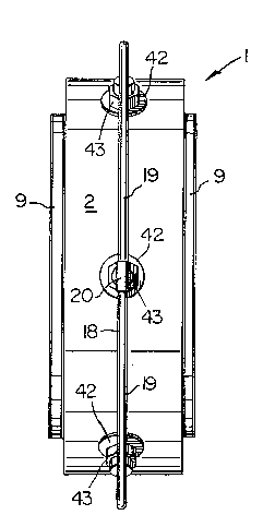
In general, catalytic heaters which rely on ambient
air for operation are self limiting. A simple, effective
solution to the problem includes a casing with an open front
end, a screen on such front end, a catalyst pad in the casing
behind the screen, and diffuser pads for receiving a gas/air
fuel mixture from a mixer which creates the mixture and
introduces the mixture through the rear wall of the casing.
Channels or dikes in the diffuser pads ensure even
distribution of the gas/air fuel mixture to the catalyst pad.


Claims

Note: Claims are shown in the official language in which they were submitted.


The embodiments of the invention in which an exclusive
property or privilege is claimed are defined as follows:
1. A catalytic heater comprising:
a) casing means, said casing means including side walls,
a rear wall and end walls; screen means closing an
open front end of said casing means; catalyst pad
means in said casing means adjacent to said screen
means; diffuser pad means in said casing means between
said catalyst pad means and said rear wall for
distributing a fuel mixture to said catalyst pad
means; and inlet means in said rear wall of said
casing means for introducing the fuel mixture into
said casing means; and
b) said diffuser pad means includes a first, high density
ceramic fiber pad adjacent said rear wall, a plurality
of low density ceramic second fiber pads between said
first pad and said catalyst pad means, and high
density ceramic fiber dike means separating said
second fiber pads from each other.
2. A catalytic heater according to claim 1, wherein said
inlet means includes separate inlets for introducing the
fuel mixture into each of said second pads.
3. A catalytic heater according to claim 1, wherein said
inlet means includes means for introducing a fuel mixture
into the centre of each said second fiber pad, ensuring
uniform distribution of said mixture in each said second
fiber pad.
4. A catalytic heater according to claim 3, wherein said
means for introducing a fuel mixture comprises a plurality
of inlets in the rear wall of said casing means.
5. A catalytic heater according to claim 1, wherein said
inlet means includes mixer means connected to a source of

gas under pressure for receiving gas therefrom and for
introducing air into the gas to create the fuel mixture.
6. A catalytic heater according to claim 5, wherein said
mixer means includes an elongated tubular body for
conveying gas to said casing means; restricted orifice
means in said body through which the gas passes to create
a low pressure zone in said body, and radial openings in
said body communicating with said low pressure zone for
introducing air into the gas in said body.
7. A catalytic heater according to claim 1, wherein said
diffuser pad means includes a first ceramic fiber pad
adjacent said rear wall, a second ceramic fiber pad
adjacent said catalyst pad, and a third ceramic fiber pad
intermediate said first and third pads.
8. A catalytic heater according to claim 7, wherein
passage means extends centrally along the length of said
second pad.
9. A catalytic heater according to claims 1, 2, 3, 4, 5,
6, 7 or 8, wherein said casing means is semi-cylindrical,
and said screen means is located on the interior side of
the cylinder.
10. A catalytic heater comprising:
a) casing means including side walls, a rear wall and end
walls and an open front end;
b) screen means closing the open front end of said casing
means;
c) catalyst pad means in said casing means adjacent to
said screen means;
d) diffuser pad means in said casing means between said
catalyst pad means and said rear wall for distributing
a fuel mixture to said catalyst pad means;

e) inlet means in said rear wall of said casing means for
introducing the fuel mixture into said casing means;
f) said diffuser pad means having a first portion forming
a uniform layer between said casing means and said
catalyst pad means;
g) said diffuser pad means having second and third
portions located between said first portion and said
casing means;
h) said second and third portions being spaced apart a
sufficient distance to form a distinct passage; and,
i) whereby, the passage promotes the uniform flow of the
fuel mixture along the length of said casing means.
11. A catalytic heater according to claim 10, wherein said
inlet means includes mixer means connected to a source of
gas under pressure for receiving gas therefrom and for
introducing air into the gas to create the fuel mixture.
12. A catalytic heater according to claim 11, wherein said
mixer means includes an elongated tubular body for
conveying gas to said casing means; restricted orifice
means in said body through which the gas passes to create
a low pressure zone in said body, and radial openings in
said body communicating with said low pressure zone for
introducing air into the gas in said body.
13. A catalytic heater according to claim 10, wherein said
diffuser pad means includes a first ceramic fiber pad
adjacent said rear wall, a second ceramic fiber pad
adjacent said catalytic pad, and a third ceramic fiber pad
intermediate said first and third pads.
14. A catalytic heater according to claim 13, wherein said
passage means extends centrally along the length of said
second pad.

15. A catalytic heater according to claim 10, wherein said
casing means is semi-cylindrical, and said screen means is
located on the interior side of the cylinder.

Description

Note: Descriptions are shown in the official language in which they were submitted.


20 1 5638
-
This invention relates to a catalytic heater.
The device of the present invention was
specifically designed for user in a pipe heating
apparatus of the type disclosed in applicant's
co-pending Canadian patent application, Serial No.
2,004,221, filed November 29, 1989. However, the
heater of the present invention can be used in other
situations requiring a catalytic heater.
When using flameless, gas fired, catalytic
heaters, it is common practice to introduce fuel into
a gas-tight housing where the fuel expands to fill the
housing completely. As the fuel passes through the
catalyst bed located on the front surface of the
housing, ambient air mixes with the fuel permitting
catalytic oxidation to occur in the catalyst bed. The
catalyst bed usually consists of platinum group metals
or compounds carried on a ceramic wool or ceramic
board. The products of the catalytic reaction, namely
carbon dioxide and water vapour pass or are discharged
through the front surface of the catalyst bed.
Convection currents dissipate the products of reaction
and re-introduce oxygen from the atmosphere to sustain
the catalytic reaction.
The main limiting factor controlling the rate
of catalytic reaction per unit area of catalyst bed is
the rate of convection flow over the active
catalytic surface. The rate of reaction is greatly
reduced when the catalyst bed is horizontal,
because convection circulation is substantially

2~5~
reduced. One solution to the problem is the use of fans to
increase air flow of the catalytic surface.
The object of the present invention is to offer a
more effective solution to the above defined problem by
providing a relatively simple catalytic heater, in which a
gas/air mixture is introduced into the heater so that a
substantially large quantity of fuel mixture is uniformly
delivered to the catalyst bed.
The use of the heater of the present invention
permits substantial increases (as high as 33%) in heat output
per unit area of catalyst bed. Moreover, the introduction of
a fuel mixture into a housing under pressure dramatically
reduces the problem of operating a catalytic heater upside
down or face down, i.e. there appears to be no reduction in
the rate of catalytic reaction when the heater is operated
face down.
The invention will be described in greater detail
with reference to the accompanying drawings, which illustrate
preferred embodiments of the invention, and wherein:
Figure 1 is a side view of a catalytic heater in
accordance with the present invention;
Figure 2 is a rear view of the catalytic heater of
Fig. l;
Figure 3 is a front view of the catalytic heater of
Figs. 1 and 2;

2~ 8
Figure 4 is a cross section taken generally along
line IV-IV of Fig. l;
Figure 5 is a front view of a second embodiment of
the catalytic heater in accordance with the present invention;
Figure 6 is a cross section taken generally along
line VI-VI of Fig. 5;
Figure 7 is an end view of the catalytic heater of
Figs. 5 and 6;
Figure 8 is an exploded, isometric view of the
catalytic heater of Figs. 5 to 7;
Figures 9 and 10 are end views of a mixer used in
the heater of Figs 5 to 8; and
Figure 10 is a longitudinal sectional view of the
mixer of Figs. 9 and 10.
Referring to Figs. 1 to 4, one embodiment of the
catalytic heater of the present invention includes a
semicylindrical housing generally indicated at 1. The
housing, which is generally rectangular in cross section, is
defined by integral rear and side walls 2 and 3,
respectively. The open front end of the housing is closed by
a screen 6. Flanges 7 are provided on the front, free
ends of the side walls 3 for supporting a ledge 9. A catalyst
pad 10 and the screen 6 are sandwiched between the ledge 9 and
a bezel or frame 11 of generally L-shaped cross section.
The bezel 11 is connected to the ledge 9 by a plurality of
spaced apart rivets 13. Three ceramic fiber pads or layers

- 20 1 5638
14, 15 and 16 are sandwiched between the rear wall 2 of the
casing 1 and the catalyst pad 10. In this case, the pads are
formed of Kaowool (trade-mark), but other ceramic fiber may
be used in such pads.
Gas is introduced into the rear of the housing L via
an inlet manifold 18. The manifold is defined by a plurality
of lengths of pipe 19 interconnected by tee joints 20. Gas
under pressure is introduced into one end 22 of the manifold
18. The other end 23 of the manifold 18 is either plugged or
connected to additional catalytic heaters (not shown). At
least some of the gas entering each tee joint 20 is discharged
through the stem 24 of the joint into a short tube 26, which
extends into a gas/air mixer generally indicated at 27.
The mixer 27 (Fig.4) is defined by an elongated
tubular body 28 with a disc 30 containing a restricted orifice 31
mounted therein near the outwardly tapering inlet end 32. The
restricted orifice creates a low pressure area in the mixer 27
downstream of the orifice in the direction of gas flow. The
disc 30 is on one end of a short tube 34, which is inserted
into the externally threaded end of the tube 26 for retaining
the latter and the disc in the internally threaded inlet end
32 of the mixer body 28. An annular groove 36 is provided in
the body 28 downstream of the orifice 31 in the direction of
gas flow. A plurality (in this case four) of radially
extending openings 37 in the bottom of the groove 36 admit air

2~
-
to the gas stream, i.e. air is drawn into the low pressure
area of the gas stream for mixing therewith. The body 28 is
mounted in a sleeve 38 which extends into a tubular connector
or so-called spud 40. The connector 40 is externally threaded
for receiving a gasket 41, a washer 42 and a nut 43. The
enlarged inner end or head 45 of the connector engages the
outer wall 2 of the housing 1 to retain the connector in the
housing. Thus, the connector 40 is in the form of a hollow
bolt.
Gas and air entering the housing 1 are discharged
into a passage 46 extending the length of the intermediate
layer 15 of ceramic fiber. The provision of the passage 46
ensures the uniform flow of gas along the entire length of
the heater.
With reference to Figs. 5 to 8, a flat version of
the catalytic heater includes a rectangular housing generally
indicated at 50, the open front end of which is closed by a
screen 51 and a L-shaped cross section bezel or frame 52. The
housing 50 is defined by integral rear and side walls 54 and
55, respectively and end walls 56. Flanges 57 extending
outwardly from the inner free ends of the side and end walls
receive rivets 59 (Figs. 5 to 8) for connecting the frame 52
to the housing 50. The housing 50 contains a catalyst pad
60, a high density rear ceramic fiber pad 62, high density
transversely extending ceramic fiber dikes 63, and low
density front ceramic fiber pads 64.

-
A gas/air mixture is introduced into the housing 50
via elbows 66, tubes 67, mixers 68, second elbows 69 and
inlet connectors 70. The elbows 66 are connected to a source
of gas under pressure. The mixer 68 (Figs. 9 to 11) like the
mixer 27, includes an elongated body 72 with an internally
threaded, tapering inlet end 73 for receiving the tube 67, a
disc 74 with a restricted orifice 76 and a short tube 77. A
plurality of radially extending air inlet openings 78 are
provided in an annular groove 79 in the body downstream of the
orifice 76 in the direction of gas flow. A sleeve 81 on the
body 72 extends into the elbow 69.
The connector 70 is similar to the connector 40,
including external threads for receiving a washer 83 in the
casing 50, and a gasket 84, a washer 85 and a nut 86 outside
of the casing 50. A gas/air mixture is discharged through the
hexagonal head 88 of the connector 40 into a short cylindrical
passage 89 through the pad 62. The passage 89 communicates
with the centre of the pad 64. The dikes 63 form boundaries
between cells containing the pads 64, which act as diffusers
for uniform delivery of fuel mixture to the catalyst pad 60.

Representative Drawing
A single figure which represents the drawing illustrating the invention.
Administrative Status

2024-08-01:As part of the Next Generation Patents (NGP) transition, the Canadian Patents Database (CPD) now contains a more detailed Event History, which replicates the Event Log of our new back-office solution.

Please note that "Inactive:" events refers to events no longer in use in our new back-office solution.

For a clearer understanding of the status of the application/patent presented on this page, the site Disclaimer , as well as the definitions for Patent , Event History , Maintenance Fee  and Payment History  should be consulted.

Event History

Description Date
Inactive: Expired (new Act pat) 2010-04-27
Inactive: IPC from MCD 2006-03-11
Letter Sent 2002-03-05
Inactive: Entity size changed 2002-02-14
Inactive: Late MF processed 2002-01-31
Letter Sent 2001-04-27
Grant by Issuance 1995-11-14
Request for Examination Requirements Determined Compliant 1993-03-22
All Requirements for Examination Determined Compliant 1993-03-22
Application Published (Open to Public Inspection) 1991-10-27

Abandonment History

There is no abandonment history.

Fee History

Fee Type Anniversary Year Due Date Paid Date
MF (patent, 8th anniv.) - small 1998-04-27 1998-01-27
MF (patent, 9th anniv.) - small 1999-04-27 1999-01-08
MF (patent, 10th anniv.) - small 2000-04-27 2000-02-18
MF (patent, 11th anniv.) - standard 2001-04-27 2001-03-27
Reversal of deemed expiry 2001-04-27 2001-03-27
Registration of a document 2002-01-28
MF (patent, 12th anniv.) - standard 2002-04-29 2002-04-23
MF (patent, 13th anniv.) - standard 2003-04-28 2003-04-25
MF (patent, 14th anniv.) - standard 2004-04-27 2004-04-22
MF (patent, 15th anniv.) - standard 2005-04-27 2005-04-14
MF (patent, 16th anniv.) - standard 2006-04-27 2006-04-24
MF (patent, 17th anniv.) - standard 2007-04-27 2007-03-19
MF (patent, 18th anniv.) - standard 2008-04-28 2008-03-06
MF (patent, 19th anniv.) - standard 2009-04-27 2009-03-27
Owners on Record

Note: Records showing the ownership history in alphabetical order.

Current Owners on Record
CCI THERMAL TECHNOLOGIES INC.
Past Owners on Record
ALAN KIRBY
Past Owners that do not appear in the "Owners on Record" listing will appear in other documentation within the application.
Documents

To view selected files, please enter reCAPTCHA code :


To view images, click a link in the Document Description column (Temporarily unavailable). To download the documents, select one or more checkboxes in the first column and then click the "Download Selected in PDF format (Zip Archive)" or the "Download Selected as Single PDF" button.

List of published and non-published patent-specific documents on the CPD .

If you have any difficulty accessing content, you can call the Client Service Centre at 1-866-997-1936 or send them an e-mail at CIPO Client Service Centre.

({010=All Documents, 020=As Filed, 030=As Open to Public Inspection, 040=At Issuance, 050=Examination, 060=Incoming Correspondence, 070=Miscellaneous, 080=Outgoing Correspondence, 090=Payment})


Document
Description 
Date
(yyyy-mm-dd) 
Number of pages   Size of Image (KB) 
Abstract 1995-11-13 1 16
Description 1995-11-13 6 201
Abstract 1995-11-13 1 16
Claims 1995-11-13 4 131
Drawings 1995-11-13 5 131
Representative drawing 1999-07-15 1 10
Maintenance Fee Notice 2002-02-13 1 179
Late Payment Acknowledgement 2002-02-17 1 172
Maintenance Fee Notice 2002-02-13 1 179
Fees 2003-04-24 1 30
Fees 1998-01-26 1 44
Fees 2002-01-30 1 36
Fees 2001-03-26 1 29
Fees 2002-04-22 1 32
Fees 1999-01-07 1 36
Fees 2000-02-17 1 30
Fees 2004-04-21 1 30
Fees 2005-04-13 1 27
Fees 2006-04-23 1 28
Fees 2007-03-18 1 29
Fees 2008-03-05 1 29
Fees 2009-03-26 1 30
Fees 1997-01-08 1 34
Fees 1996-01-30 1 33
Fees 1994-03-20 1 31
Fees 1995-03-26 1 38
Fees 1993-04-21 1 32
Fees 1992-06-03 1 32
Correspondence 1992-06-03 1 37
Prosecution correspondence 1993-03-21 1 34
Examiner Requisition 1993-05-31 1 68
Prosecution correspondence 1993-11-25 3 86
Prosecution correspondence 1992-09-07 1 36
Prosecution correspondence 1992-01-07 1 35
PCT Correspondence 1990-10-30 1 25
Courtesy - Office Letter 1990-10-23 1 21
Courtesy - Office Letter 1992-02-23 1 14
Courtesy - Office Letter 1992-08-19 1 14
Courtesy - Office Letter 1992-11-16 1 43
Courtesy - Office Letter 1992-11-15 1 44
Courtesy - Office Letter 1993-04-19 1 54
PCT Correspondence 1995-09-05 2 63
PCT Correspondence 1992-09-17 1 39
PCT Correspondence 1992-11-29 2 67