Note: Descriptions are shown in the official language in which they were submitted.
2015950
System for Continuously Replenishing Melt
Field of the Invention
The preæent invention relates to apparatus for
growing hollow tubular crystalline bodies, and more
particularly to apparatus for delivering solid silicon
particles to the crucible of such crystal growing
apparatus before and/or during the growth process.
Background of the Invention
As is known, apparatus for growing hollow, tubular
crystalline bodies of the type disclosed in U.S.
Patent No. 4,544,S28 comprise a crucible for
supporting molten silicon which constitutes the feed
material from which the crystalline body is grown. In
the past, the silicon melt was replenished in batches
rather than continuously so as to avoid thermally
shocking the system, thereby catastrophically
terminating the crystal-growing process. Such batch
replenishment was found to be a relatively slow and
inefficient method of adding silicon particles to the
melt.
To overcome the problems associated with batch
replenishment, a system was developed for continuously
replenishing the melt. This system is described in
U.S. Patent No. 4,661,324, issued April 28, 1987 in
the name of Sink et al. (the 324' patent). The system
of the 324' patent includes (1) a conduit leading up
through the crucible and termina~ing in the interior
of the inner after-heater of the furnace above~the tip
of the die and (2) a chip thruster coupled to the
2015950
-2-
conduit and to a source of solid irregularly-shaped
silicon particles. Silicon particles are fed into the
chip thruster which p~riodically ~orces a
predetermined volume of the particles up through the
conduit and into the interior of the inner
after-heater. Thereafter, the chips fall, under the
pull of gravity, into the melt.
Unfortunately, the system of the 324' patent
suffers from several problems. First, because the
chip thruster portion of the system includes a
significant number of mechanical parts, and because
the chip thruster is constantly handling abrasive
material (i.e. irregularly-shaped particles of solid
silicon), the chip thruster tends to break down.
Second, the abrasive silicon particles tend to erode
or abrade away minute portions of the metallic
components of the chip thruster, which portions are
delivered along with the silicon particles into the
melt. These minute portions of metal tend to
contaminate the melt. Third, because the mass of a
predetermined volume of irregularly-shaped silicon
particles varies from one volume of particles to the
next depending upon how the chips orient themselves
relative to one another, and because the chip thruster
ejects a predetermined volume, not mass, of particles
into the furnace, it is virtually impossible to
repeatedly add a predetermined mass of chips to the
furnace. To minimize thermal excursions to the level
n~resC~ry to maintain a substantially continuous
crystal growth process, it is important where
irregularly-shaped silicon particles are used as the
",' '- . -, . . ~..' . , :
. . ,
2015950
-
-3-
feed material that a predetermined mass of particles
always be added to the melt. For the reasons noted
above, the chip thruster system is not capable of
repeatedly providing such a predetermined mass of
irregularly-shaped particles to the melt.
Objects and Summary of the Invention
One object of the present invention is to provide
a system for continuously replenishing the silicon
melt in an apparatus for growing hollow, tubular
crystalline bodies which is highly reliable and does
not inadvertently add contaminants to the melt.
A second object of the present invention is to
provide a system for continuously replenishing the
silicon melt in an apparatus for growing hollow,
tubular crystalline bodies in a way which does not
create unacceptably large thermal excursions or
perturbations of the melt.
These and other objects are achieved by a system
for continuously replenishing the silicon melt in a
crucible in a crystal furnace, e.g., of the type
disclosed in U.S. Patent No. 4,544,528 to Stormont et
al., which has been modified to include a conduit
extending up through the crucible and terminating in
the interior of the inner after-heater above the tip
of the die. The system includes a container for
storing spherical, solid silicon particles of,
predetermined diameter, a receiving chamber coupled
with the conduit and with the container, and a high
pressure gas ~et coupled with the receiving chamber. A
particle dispenser comprising a vibrator, a second
201~950
-4-
high pressure gas jet, or some other means is provided
for causing the silicon particles to move from the
container to the receiving chamber. Silicon particles
in the receiving chamber are forced up through the
conduit into the interior of the inner-after heater of
the crystal growth furnace directly above the crucible
by the high pressure gas jet. Thereafter, the silicon
particles fall, under the pull of gravity, down into
the melt contained in the crucible. A deflector is
preferably provided in the crystal growth furnace
directly above the upper end of the conduit for
deflecting silicon particles emitted from the conduit
so that they fall into the melt in a substantially
evenly-distributed pattern over the surface of the
melt, thereby minimizing the formation of currents or
thermal excursions in the melt.
Brief Description of the Drawings
For a fuller understanding of the nature and
objects of the present invention, reference should be
made to the following detailed description taken in
connection with the accompanying drawings wherein:
Fig. 1 is a cross-sectional side elevation view of
a crystal growth furnace which is designed to be used
with the silicon feed system of the present invention;
and
Fig. 2 is a schematic cross-sectional side
elevation of the silicon feed system of the present
invention.
Detailed Descri~tion of the Invention
. .
~. ,
2015950
-5-
Referring to Figs. 1 and 2, the present invention
is a system 18 for continuously supplying spherical,
solid silicon particles to the crucibie of an
apparatus 20 for growing hollow, tubular crystalline
bodies of the type disclosed in U.S. Patent No.
4,544,528 (the '528 patent).
Apparatus 20 comprises a furnace enclosure 22
within which are disposed crucible 24, and inner and
outer after-heaters 26 and 28. Crucible 24 is a
short, hollow, open-topped right prism or right
circular cylinder centrally disposed within enclosure
22. Inner a~ter-heater 26 has a hollow interior 30
and a top plate 32 sealing off top end of the inner
after-heater. The bottom of the inner after-heater 26
is open, and the inner after-heater is positioned
directly above crucible 24 whereby interior 30 of the
inner after-heater is coupled with the interior of the
crucible. Inner after-heater 26 is located in the
hollow interior of outer after-heater 28.
Apparatus 20 additionally comprises a capillary
die 34, a susceptor 36 and a seed assembly 38, all of
which are positioned in enclosure 22. Preferably,
-capillary die 34 is an integral part of the sidewall
of crucible 24. The shape and dimension of the end
face 40 of die 34 are selected to control the form and
size of the grown crystal. Susceptor 36 is a short,
hollow open-topped cylindrical or prismatic body
dimensioned to accommodate cruci~le 24. Susceptor 36
may be an integral part of the die/crucible assembly.
Seed assembly 38 includes a seed holder 42 and a seed
2015950
-6-
44. Seed assembly 38 is attached to a pulling
mechanism 39 which is adapted to move seed holder
axially toward and away from die 34.
Apparatus 20 further includes a radio-frequency
heating coil 46 surrounding enclosure 22 adjacent
crucible 24. Heating coil 46 maintains the silicon in
crucible 24 in a molten state.
As is known, the crystalline body is grown by
positioning seed 44 in contact with the die end face
40 and then pulling the seed away from the die end
face so as to form a meniscus between the seed and the
die end face. As the seed is pulled away from the die
end face, the portion of the meniscus closest to the
seed solidifies. As the seed crystal is pulled even
farther away from the die, new molten silicon is drawn
by capillary action onto the die end face and molten
silicon already present in the meniscus hardens to the
solidified silicon attached to the seed, so as to form
an elongate crystalline body.
For a more detailed description of the
construction and operation of apparatus 20, attention
is directed to the '528 patent.
For the purpose of the present invention,
apparatus 20 is modified to include a conduit 60
having a central bore 62. Conduit 60 extends in turn
through the bottom walls of enclosure 22, susceptor 36
and crucible 24, as shown in Fig. 1. The insi,de
diameter of conduit 60 is slightly greater than the
outside diameter of the largest particles of silicon
to be supplied by the system 18 of the present
invention, as discussed below. Preferably, conduit 60
20159~0
-
-7-
is made of fused silica. Conduit 60 is positioned in
the center of crucible 24 and is sized so that its top
end 64 extends up into the interior 30 of inner
after-heater 26, slightly above the top surface of the
melt supported in crucible 24 when the crucible is
full. Thus, conduit 60 provides a passageway from the
region below apparatus 20 up through the bottom wall
of crucible 24 into the interior 30 o~ inner
after-heater 26. Preferably, a convex conical
deflector 66 is attached to the bottom surface of top
plate 32 directly above the top end 64 of conduit 60
so that the pointed end 67 of the def ector is
coaxially aligned with central bore 62.
In other respects, the crystal growth furnace
illustrated in Fig. 1 is identical to the furnace
described in the '528 patent.
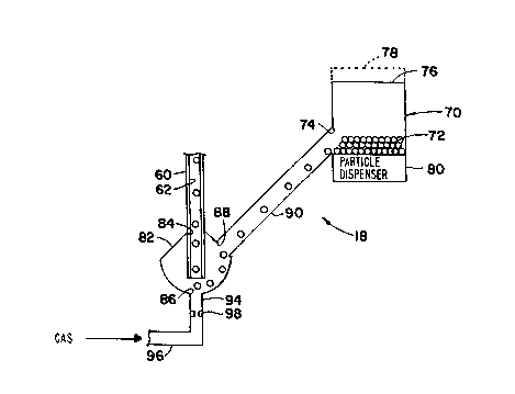
Silicon feed system 18 includes a hollow container
70 for storing particles 72 of solid silicon.
Particles 72 are spherical and preferably have an
outside diameter of 1 millimeter, with a tolerance of
+ 1/2 millimeter. Thus, the mass and volume of each
of the particles i2 is roughly equal.
Container 70 includes an aperture 74 positioned at
the bottom of the container through which particles 72
are dispensed from the container and an open top end
76 through which particles 72 are supplied to the
container. As described hereinafter, container 70 may
optionally include a cover 78 (shown in phantom in
Fig. l) for sealing open end 76.
System 18 further includes particle dispenser 80
coupled with container 70 for causing silicon
' ^
201S950
-8-
particles 72 stored in the container to exit the
container via aperture 74. Preferably, particle
dispenser 80 comprises a source of pressurized fluid,
e.g., argon gas, for pressurizing the interior of
container 70 so as to force particles 72 out ~f
aperture 74. Where particle dispenser 80 constitutes
a source of pressurized fluid, container 70 should
include cover 78 or otherwise be designed so as to
permit the interior of the container to be suitably
pressurized. Alternatively, particle dispenser 80 may
comprise a vibrator for causing container 70-to
vibrate so that particles 72 migrate toward aperture
74 where, due to the combined effect of gravity and
the weight of adjacent particles, the particles pass
through aperture 74. As those of ordinary skill in
the art will readily appreciate, particle dispenser 80
may comprise other means for causing particles 72 to
exit container 70 via aperture 74.
System 18 also includes a hollow receiving chamber
82. The latter includes a top opening 84, a bottom
opening 86, and a side opening 88. Receiving chamber
82 is attached at its top opening 84 to conduit 60 so
that central bore 62 communicates with the interior of
the receiving chamber. Preferably the bottom end of
conduit 60 extends down into receiving chamber 82 as
shown. Receiving chamber 82 is positioned relative to
container 70 so that the side opening 88 of the
receiving chamber is positioned a suitable distance
below aperture 74 of the container, as discussed
hereinafter. Preferably, the bottom portion of
receiving chamber 82 tapers inwardly toward bottom
,
2û15950
-
g
opening 86 so as to funnel silicon particles 72
present in the chamber toward bottom opening 86.
Receiving chamber 82 is preferably made of a
non-metallic material which cannot be readily eroded
or abraded by silicon particles 72, such as plastic.
System 18 comprises a hollow pipe 90 attached to
container 70 at its aperture 74 and to receiving
chamber 82 at its side opening 88, so that a
continuous passageway is provided from the interior of
container 70, through aperture 74, the interior of
pipe 90, and side opening 88 into the interior of
receiving chamber 82. Container 70 is positioned
above receiving chamber 82 a distance selected so that
pipe 90 slopes downwardly at a relatively steep angle,
e.g. 45 with respect to a horizontal plane, from
container 70 to receiving chamber 82. Pipe 90 is
preferably made from a non-metallic material which is
not easily eroded by particles 72.
System 18 also includes an inlet port 96 which
leads to a tube 94 that is connected to the bottom
opening 86 of receiving chamber 82, so as to
communicate with the interior of the receiving
chamber. Inlet port 96 is connected to a source of
pressurized fluid (not shown), e.g. a source of argon
gas under pressure. Tube 94 directs a stream of
pressurized fluid up into the interior of receiving
chamber 82 via its bottom opening 86. Depending upon
the size of tube 94, it may be desirable to provide a
restricted orifice 98 in the tube directly below
bottom opening 86 in receiving chamber 82 to increase
the velocity of the fluid into receiving chamber 82.
201~9~0
-
--10--
The volume flow rate af the gas introduced via
port 96, the size of orifice 98, if provided, the
vertical distance between bottom opening 86 of
receiving chamber 82 and top end 64 of conduit 60, and
the vertical spacing between top end 64 of conduit 60
and the pointed end 67 of deflector 66 are selected so
as to ensure particles 72 present in receiving chamber
82, each of which have a substantially identical and
known mass, as noted above, are entrained in the gas
jet provided by tube 94 and are driven upward through
conduit 60 with sufficient force to contact deflector
66 provided in the interior 30 of inner after-heater
26. Of course, these parameters will vary with
changes in mass and diameter of the particles 72 and
with changes in one or more of the parameters relative
to the other parameters. In a working embodiment of
system 18, argon gas was fed from a gas source having
a pressure of about 20 pounds per square inch through
inlet port 96 at a volume flow rate of 5 liters STP
(i.e., a temperature of degrees C and an atmospheric
pressure of 760 mm Hg) per minute, orifice 98 had an
inside diameter of 0.031 inches, the vertical distance
from top end 64 of conduit 60 to the bottom opening 86
of receiving chamber 82 was about 17 inches, and top
end 64 was positioned about 1.73 inches below the
pointed end 67 of deflector 66. Spherical silicon
particles having an outside diameter of about 1
millimeter, plus or minus 1/2 millimeter, were used as
the feed material.
To use the melt replenishment system 18 of the
present invention, a quantity of spherical, solid
2015950
silicon particles 72, preferably having an outside
diameter of about 1 millimeter, plus or minus 1/2
millimeter, is placed into container 70 through its
open top end 76. Then a stream of pressurized fluid,
e.g. argon gas, is directed via inlet port 96 and tube
94 up through bottom opening 86 into receiving chamber
82. Particle dispenser 80 is then activated so that
silicon particles 72 are dispensed from container 70
through its aperture 74. Where particle dispenser 80
comprises a source of pressurized fluid, cover 78 is
attached to container 70 before the particle dispenser
is activated. Particles 72 dispensed through aperture
74 enter pipe 90 and slide downwardly, under the pull
of gravity, through the pipe and side opening 88 into
receiving chamber 82.
Upon entering receiving chamber 82, particles 72
slide down along the inwardly-tapering walls of the
bottom portion of receiving chamber 82 toward bottom
opening 76. As particles 72 approach bottom opening
86, they are entrained in the jet of pressurized fluid
introduced by tube 94, whereby that gas stream carries
the part~cles up into and through the central bore 62
of conduit 60 and out through the top end 64 of the
conduit. Then, the particles 72 continue to travel
upwardly within the inner after-heater 26 until they
contact and bounce off deflector 66, if provided, and
fall into the melt. Deflector 66 evenly distributes
particles 72 so they enter the melt over substantially
the entire surface thereof, thereby minimizing the
formation of locally cool zones which can give rise to
currents and thermal excursions in the melt which can
.,;
; ... .
;~
2015950
-12-
catastrophically terminate the crystal growth process.
Where deflector 46 is not provided, particles 72
merely bounce off the bottom surface of plate 32 and
fall into the melt. In certain cases, acceptable
results can be obtained without the use of deflector
66.
Although it is intended that melt replenishment
system 18 will be operated using spherical silicon
beads, the system can also be operated using
irregularly-shaped silicon particles having a specific
dimensional characteristic. Specifically, silicon
particles having a parameter L/D ranging from about 1
to 1.2 can generally be satisfactorily employed in
system 18. The parameter L/D refers to the length of
the silicon particle as measured along its long axis
divided by the diameter of the particle as measured
along an axis extending perpendicular to the long
axis. Clearly, for spherical particles the parameter
L/D is equal to 1 whereas for long, thin particles the
parameter L/D could be equal to 5 or more.
An important advantage of the melt replenishment
system of the present invention is that relatively
long crystalline bodies can be grown using a c,rystal
growing apparatus coupled with the present system
since the length of the growing crystalline body is
not limited by the quantity of molten silicon
contained in the crucible of the crystal-growing
apparatus. Relatedly, the present melt replenishment
system additionally facilitates the growth of
relatively long crystalline bodies by adding solid
silicon particles to the melt in a fashion minimizing
. ' -
2015950
-13-
formation of thermal excursions in the melt. 'As is
known, the possibility that a thermal excursion of the
magnitude causing the catastrophic termination of the
crystal growth process will occur increases with the
length of the growing crystalline body. For reasons
of cost and manufacturing efficiency, it is desirable
to grow relatively long crystalline bodies.
Since certain changes may be made in the above
apparatus and method without departing from the scope
of the invention herein involved, it is intended that
all matter contained in the above description or shown
in the accompanying drawing shall be interpreted in an
illustrative and not in a limiting sense.
:,