Note: Descriptions are shown in the official language in which they were submitted.
~116268
-- 1 .
SHUTTLE VA~VE WITH SPIKE~APPLY D~MPIN~
The present invent:ion relates generally to a
~ shuttle valve with spike-app:Ly damping, and in particular
to a shuttle valve for an anti-lock braking syc,tem.
Shuttle valves utilized with solenoids are illus-
trated in Brown U. S. Patent ~o. 4,620,565 and Martinic U.
S. Serial No. 07/274,076. In many vehicle anti-lock brak-
ing systems, there is need for a mechanism which prevents
the premature full travel of the shuttle valve during a
spike-apply of the brakes. When a vehicle operator suddenly
slams on the brakes and effects such a spike-apply of the
master cylinder and brake fluid pressure, it is necessary
that the high fluid pressure be communicated initially to
the brakes, and thereafter the shuttle valve may be dis-
placed and the anti-lock braking system will operate to
prevent skidding. If the shuttle valve is permitted to
experience full travel during the spike-apply of the
brakes, then the high pressure brake fluid will be pre-
vented initially from reaching the brakes and the braking
effect desired by the vehicle driver will not be attained.
Thus, it is highly desirable to provide an anti-lock brak-
ing system shuttle valve which includes a mechanism for
preventing the premature full travel of the shuttle valve
during spike applications of the braking system.
The present invention provides a solution to the
above problem by disclosing a shuttle valve having spike-
apply damping, comprising a valve body having therein a
stepped bore, the bore including a small diameter bore sec-
tion, reduced diameter bore section, and enlarged diameter
bore section, the small diameter bore section communicating
with a brake line connection, the reduced diameter bore
section communicating with an outlet opening and the
enlarged diameter bore section communicating with an inlet
opening, a valve member disposed within said bore and
including a ~irst diameter section received within said
3 small diameter bore section and a second diameter section
received slidably within the enlarged diameter bore sec-
tion, the first and second diameter sections having seal-
ing means thereabout engaging sealingly the small and
2016268
-- 2
enlarged diameter bore sections, and the second diameter
section including a transverse opening communicating with
a longitudinal orifice openin~ which communicates with a
chamber di,sposed at the second diameter section of the
valve member, spring means disposed within said bore and
biasing said valve member toward an at-rest position, and
a movable orifice member disposed at said first diameter
section, the movable orifice member having an orifice
therein, so that a sudden communication of high pressure
fluid via the inlet opening to the enlarged diameter bore
section results in a slightly delayed displacement of the
valve member and movable orifice member, the displacement
of the valve member and movable orifice member then caus-
ing said fluid to be communicated through said orifice and
toward said outlet opening.
One way of carrying out the invention is des-
cribed in detail below with reference to the drawings which
illustrate an embodiment in which:
Figure 1 illustrates the shuttle valve of the
present invention during normal braking; and
Figure 2 illustrates the shuttle valve after dis-
placement of the valve.
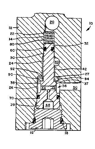
Referring now to the drawings and in particular
to Figure 1, there is shown a shuttle valve in accordance
with the present invention and indicated generally by
reference numeral 10, which includes a valve body 12 hav-
ing a cylindrical stepped bore 14. sore 14 is closed at
one end by threaded cap member 16 and seal 18, while the
other end of the stepped bore communicates with a brake
feedback line connection 20. Located between cap member
16 and ~eedback line connection 20 are small diameter bore
section 22, reduced diameter bore section 24, and enlarged
diameter bore section 26. Reduced diameter bore section
24 communicates with an outlet opening 40 and enlarged
diameter bore section 26 communicates with an inlet open-
ing 50. Located within stepped bore 14 is a valve member
30 comprising first a diameter section 32 and a second dia-
meter section indicated generally by reference numeral 36.
~(1162~8
-- 3
Second diameter section 36 includes a narrowed diameter
section 3~ and a large diameter section 39. First diameter
section 32 has a radi.us smaller than the radius of reduced
diameter bore section 24 so that fluid may flow between in-
let opening 50 and outlet opening 40 via a clearance 42.
First diameter section 32 includes thereabout a seal 60 and
second diameter section 36 includes thereabout a seal 70.
Spring 80 located in small diamete~ bore section 22 biases
valve member 30 toward engagement with the cap memb~r 16,
the position of valve member 30 in Figure 1 illustrating an
"at-rest" or '~open~' position. secon~ diameter section 36
includes a transverse opening 44 which communicates with a
longitudinal orifice opening 46 that leads to chamber 48
disposed adjacent cap member 16.
Disposed about first diameter section 32 is a mov-
able orifice member 90 which comprises an annular member
having a central opening 92 receiving first diameter sec-
tion 32. Movable orifice member 9o includes a radially
extending slot or orifice 94. First diameter section 32
and second diameter section 36 define shoulder 37 upon
which rests the movable orifice member 90. Reduced dia-
meter bore section 24 and enlarged diameter section 26
define a bore shoulder 27 which is located a distance apart
from the movable orifice member 90. Central opening 92 has
a larger diameter than first diameter section 32 so that
movable orifice member 90 is freely movable about first
diameter section 32 and can translate between the shoul-
ders 27, 37.
In an anti-lock braking system utilizing the
shuttle valve of the present invention, braking fluid
pressure is received from the master cylinder via inlet
opening 50 and communicated through enlarged diameter bore
section 2~, reduced bore section 24, and transmitted via
outlet opening 40 toward a build/decay solenoid valve
which then transmits the fluid pressure to a brake. The
brake includes the feedback line connection 20 which com-
municates with one end of bore 14 so that valve member 30
experiences thereacross a pressure differential necessary
2()~6268
- 4 -
for shuttle operation. During normal braking, brake pres-
sure is transmitted though inlet opening ~0 to outlet
opening 90 via bore 14. The pressurized fluid is trans-
mitted around movable orifice member 90 so that it passes
between shoulder 27 and member 90, into clearance 42, and
e~its outlet opening 40. In the event of a spike-apply of
the braking system by the ~ehicle operator wherein the
vehicle operator slams his foot upon the brake pedal,
there is the the sudden communication of very high brak~ng
pressure through inlet opening 50 and toward the outlet
opening 40. It is necessary for the high pressure to be
communicated to the vehicle brakes for a certain period of
time so that the vehicle operator experiences a correspond-
ing amount of initial braking response, after which the
shuttle valve may then advantageously restrict the communi-
cation of the spike-applied, high braking pressure as the
anti-lock braking system assists braking so that skidding
is prevented. In order to prevent the premature full
travel displacement of valve member 30 during such a spike-
apply of the brakes, valve member 30 receives the suddencommunication of high braking pressure via the transverse
opening 44 and then restricts fluid flow through longitu-
dinal orifice opening 46 to chamber 48. By restricting the
high pressure fluid flow through longitudinal orifice open-
ing 46 to chamber 48, there is provided a slight delay inthe displacement of valve member 30 which occurs as pres-
sure in chamber 48 increases to the extent that valve mem-
ber 30 experiences a pressure differential between chamber
48 and brake feedback line connection 20. Once the delay in
shuttling displacement has been experienced and the pres-
sure in chamber 48 (acting upon second diameter section 36
which is larger than first diameter section 32) increases,
valve member 30 will be displaced to the position illus-
trated in Figure 2. Chamber 48, second diam~ter section 36,
seal 70, bore 14, and cap member 16 define a variable
volume chamber 49. In Figure 2, shuttle valve member 30
has moved upwardly so that movable orifice member 90 is
now trapped between shoulders 27 and 37. As a result,
20~6268
fluid commUnication between inlet opening 50 and outlet
opening 40 no~ must pass through the orifice opening 94
which greatly reStriCtS pressurized fluid ~low. Thus,
after an initial delay in the displacement of the shuttle
valve so that high pressure fluid from the spike-apply is
permitted to be communicated to a brake of the vehicle,
the shuttle valve then moves to the position illustrated
in Figure 2 wherein the movable orifice member restricts
pressurized fluid communication with the associated brake.
By this time, the anti-lock braking system is operative so
that skidding of the vehicle is prevented. During anti-
lock braking system operation, the shuttle valve is in the
displaced position shown in Figure 2 wherein communication
of fluid pressure continues to be through inlet opening 50,
lS enlarged dlameter bore section 26, movable orifice opening
94, clearance 42, and outlet opening 40. When anti-lock
braking system operation terminates, or when the spike-
apply application of the brakes has terrninated, the
shuttle valve will return toward the at-rest position
shown in Figure 1. Because the movable orifice member 90
is freely movable between shoulders 27 and 37 and also
laterally about first diameter section 32, the movement of
member 90 in combination with the backflow of fluid effects
a washing or flushing of any contaminates or buildup of
material at movable orifice opening 94. A common problem
experienced by fixed orifices is that a buildup of contami-
nant material in the brake fluid may eventually cause clog-
ging of the fixed orifice. Movable orifice member 90 eli-
minates this problem by having orifice opening 94 disposed
30 within a movable member so that the movement and flow of
fluid thereabout will effect continually a flushing or
cleansing of the orifice, and thereby prevent any buildup
of material which could cause clogging of the orifice.
The shuttle valve of the present invention pro-
vides a solution to the spike-apply caused premature full
travel of a shuttle valve of an anti-lock braking system.
The shuttle valve not only provides the desired delay of
displacement of the shuttle valve, but also provides a
2016268
-- 6 --
desired restriction of fluid flow after displacement and
during anti-lock braking system operation. Additionally,
it provides a self-cleansing or flushing of the orifice
opening which obviate the clogging problems so commonly
experienced by fixed orifices. The shuttle valve of the
present invention is particularly useful within anti-lock
braking systems where shuttle valves may be utilized in
combination with solenoid valves that isolate, build, and
decay fluid pressure being communicated with a brake of
the vehicle. Typically, the anti-lock braking system may
include a number of shuttle valves, such as one shuttle
valve for each of the brakes or fewer shuttle valves if
two of the brakes are connected and operated in common.