Language selection

Search

Patent 2016295 Summary

Third-party information liability

Some of the information on this Web page has been provided by external sources. The Government of Canada is not responsible for the accuracy, reliability or currency of the information supplied by external sources. Users wishing to rely upon this information should consult directly with the source of the information. Content provided by external sources is not subject to official languages, privacy and accessibility requirements.

Claims and Abstract availability

Any discrepancies in the text and image of the Claims and Abstract are due to differing posting times. Text of the Claims and Abstract are posted:

  • At the time the application is open to public inspection;
  • At the time of issue of the patent (grant).
(12) Patent: (11) CA 2016295
(54) English Title: WATER HEATER WITH HEAT TRAP FOR DIP TUBE
(54) French Title: CHAUFFE-EAU A TUBE D'ARRIVEE MUNI D'UN CLAPET DE NON-RETOUR
Status: Deemed expired
Bibliographic Data
(52) Canadian Patent Classification (CPC):
  • 122/84
(51) International Patent Classification (IPC):
  • F24H 1/40 (2006.01)
  • F24H 9/12 (2006.01)
(72) Inventors :
  • THREATT, GARY S. (United States of America)
(73) Owners :
  • A.O. SMITH CORPORATION (Not Available)
(71) Applicants :
(74) Agent: MARKS & CLERK
(74) Associate agent:
(45) Issued: 1997-11-18
(22) Filed Date: 1990-05-08
(41) Open to Public Inspection: 1990-11-09
Examination requested: 1993-03-17
Availability of licence: N/A
(25) Language of filing: English

Patent Cooperation Treaty (PCT): No

(30) Application Priority Data:
Application No. Country/Territory Date
07/348,975 United States of America 1989-05-09

Abstracts

English Abstract


A hot water heater (12) has a modified dip
tube (70) with a heat trap (80, 78, 82, 74) therein.
The cold water inlet pipe (90) is threaded directly
into a spud (26) on the tank without an extra fitting
(32) otherwise required for a heat trap, the heat trap
function being performed in the dip tube (70) and
eliminating the cost of a separate external heat trap
fitting otherwise required for such function. The
travel stroke of the heat trap sealing ball (80) is
located entirely within the storage tank (14) to reduce
noise caused by movement of the ball (80).


French Abstract

Chauffe-eau (12) comportant un tube d'arrivée profond modifié (70) à l'intérieur duquel se trouve un dispositif anti-convection (80, 78, 82, 74). Le tuyau d'entrée d'eau froide (90) est directement branché au raccord (26) du réservoir et ne nécessite aucun accessoire de canalisation supplémentaire (32), habituellement requis par un dispositif anti-convection, étant donné que ce dernier se situe à l'intérieur du tube d'arrivée profond (70). Par conséquent, le coût d'un accessoire de canalisation distinct est éliminé. Afin de réduire le bruit causé par le mouvement de la bille d'étanchéité du dispositif anti-convection (80), cette dernière effectue sa course entièrement à l'intérieur du réservoir (14).

Claims

Note: Claims are shown in the official language in which they were submitted.


-7-

THE EMBODIMENTS OF THE INVENTION IN WHICH AN EXCLUSIVE
PROPERTY OR PRIVILEGE IS CLAIMED ARE DEFINED AS FOLLOWS:

1. A water heater comprising a storage tank
holding water to be heated, an opening in said tank, a
dip tube extending downwardly into said tank from said
opening for introducing water into said tank, an upper
valve seat in said dip tube, a lower stop in said dip
tube, a sealing member in said dip tube and movable
longitudinally upwardly and downwardly therein between
said upper valve seat and said lower stop, said sealing
member having a density less than water such that said
sealing member floats in water upwardly into engagement
with said valve seat to close same and prevent heat
loss upwardly through and out of said dip tube and to
prevent convection water currents upwardly through and
out of said dip tube, said sealing member moving
downwardly out of engagement with said valve seat in
response to incoming water flowing through said valve
seat and downwardly in said dip tube, an external spud
attached to said tank at said opening, and an inlet
water pipe threaded directly into said spud without an
extra fitting for a heat trap, the heat trap function
being performed in said dip tube and eliminating the
cost of a separate external heat trap fitting otherwise
required for such function.
2. The invention according to claim 1
wherein said dip tube has one or more outlet openings
discharging water into said tank, and said valve seat
is above said outlet openings.
3. The invention according to claim 2
wherein said lower stop is below said outlet openings,
such that said sealing member is movable along a travel
stroke extending above and below said outlet openings.
4. The invention according to claim 3
wherein said lower stop is at the bottom of said dip
tube.


-8-


5. The invention according to claim 4
wherein said lower stop comprises a crimped portion of
said dip tube at the bottom end thereof.
6. A water heater comprising a storage tank
holding water to be heated, a dip tube comprising a
cylindrical tube of given diameter extending downwardly
into said tank for introducing water into said tank, an
inner cylindrical tubular insert extending downwardly a
given distance into said dip tube, a lower stop in said
dip tube spaced below the bottom end of said tubular
insert, a sealing member in said dip tube having a
given diameter less than the inner diameter of said dip
tube and greater than the inner diameter of said
tubular insert, said sealing member being movable
longitudinally upwardly and downwardly in said dip tube
between said bottom end of said tubular insert and said
lower stop, said sealing member having a density less
than water such that said sealing member floats in
water upwardly into engagement with said bottom end of
said tubular insert to close same and prevent heat loss
upwardly through and out of said dip tube and to
prevent convection water currents upwardly through and
out of said dip tube, said sealing member moving
downwardly out of engagement with said bottom end of
said tubular insert in response to incoming water
flowing through said tubular insert and downwardly in
said dip tube.
7. The invention according to claim 6
comprising pressure relief means in said dip tube
relieving pressure therethrough from said tank and said
dip tube upwardly through said tubular insert when said
sealing member is seated against said bottom end of
said tubular insert.
8. The invention according to claim 7
wherein said tubular insert comprises a cylindrical


-9-


sidewall, and wherein said pressure relief means
comprises one or more slots extending radially through
said cylindrical sidewall of said tubular insert, such
that when said sealing member is seated against said
bottom end of said tubular insert, there is still
limited communication through said radial slots between
the interior of said dip tube below said sealing member
and the interior of said tubular insert above said
sealing member.
9. The invention according to claim 7
wherein said sealing member is porous and provides
pressure relief.
10. The invention according to claim 6
wherein said tubular insert has an upper portion
extending above the upper end of said dip tube and
flared radially outwardly to form a flange extending
radially outwardly beyond said dip tube.
11. The invention according to claim 10
wherein said tank has an opening therein, and
comprising a dip tube retainer mounted in said opening
and having an aperture through which said dip tube
extends, said aperture having a diameter greater than
the outer diameter of said dip tube and less than the
outer diameter of said flange of said tubular insert,
and comprising an external spud mounted to said tank at
said opening, and a cold water inlet pipe threaded into
said spud and having a lower end engaging the top of
said flange of said tubular insert in sealing relation.
12. The invention according to claim 11
comprising an annular sealing gasket between said
flange of said tubular insert and said dip tube
retainer.

Description

Note: Descriptions are shown in the official language in which they were submitted.


The invention relates to water heaters, and more
particularly to heat traps therefore.
Heat traps for water heaters are known in the art, for
example, as shown in Nickel U.s. Patent No. 4,286,573. The
heat trap prevents heat loss to the external piping system.
At the cold water inlet, the heat trap is provided by a
fitting having a ball and a valve seat. The fitting is
threadingly connected at one end to an external spud attached
to the water heater, and is thre~ingly connected at the
other end to the external cold water inlet pipe.
The present invention provides a cost reduction, and
eliminates the extra fitting otherwise required for a heat
trap. The present invention provides a heat trap in the dip
tube ext~n~in~ downwardly internally in the water heater.
Dip tubes are known in the art, for example as shown in U.S.
Patents Nos. 2,764,427, 3,726,475~ 3,776,456 and 3,864,234.
The dip tube intro~ces cold water into the water heater at a
location spaced below the top of the storage tank.
The present invention modifies the dip tube and provides
simple structure for performing the heat trap function within
the dip tube, and eliminates the cost of a separate external
heat trap fitting otherwise required for such function.
The invention also re~uces noise caused by v- -nt of a
sealing member performing the heat trap function, by locating
the travel stroke of the sealing member entirely within the
storage tank.


- ~ , . ~ .
.


In one aspect the invention provides a water heater
comprising a storage tank holding water to be heated, an
opening in said tank, a dip tube exten~ing downwardly into
said tank from said op~ning for introducing water into said
tank, an upper valve seat in said dip tube, a lower stop in
said dip tube, a sealing - ?r in said dip tube and movable
longitn~in~1ly upwardly and do..-wardly therein between said
upper valve seat and said lower stop, said sealing member
having density less than water such that said sealing member
floats in water upwardly into engagement with said valve seat
to close same and prevent heat loss upwardly through and out
of said dip tube and to ~,evel-L col.ve~ion water currents
upwardly through and out of said dip tube, said sealing
~-r moving downwardly out of ~ng~g: -nt with said valve
seat in ~e~once to incoming water flowing through said valve
seat and ~ ardly in said dip tube, an external spud
att~heA to said tank at said open;ng, and an inlet water
pipe threaded directly into said spud without an extra
fitting for a heat trap, the heat trap function being
performed in said dip tube and eliminating the cost of a
separate external heat trap fitting otherwise required for
such function.
In a further aspect the invention provides a water
heater comprising a storage tank holding water to be heated,
a dip tube comprising a cylindrical tube of given diameter
exten~ing downwardly into said tank for introducing water
into said tank, an inner cylindrical tubular insert extenAing


...... .


- lb -
downwardly a given distance into said dip tube, a lower stop
in said dip tube spaced below the bottom end of said tubular
insert, a sealing member in said dip tube having a given
diameter less than the inner ~ er of said dip tube and
greater than the inner diameter of said tubular insert, said
sealing member being movable longitu~inAlly upwardly and
dc..l. ~rdly in said dip tube between said bottom end of said
tubular insert and said lower stop, said sealing member
having a density less than water such that said sealing
- ~er floats in water upwardly into engag- - ~ with said
bottom end of said tubular insert to close same and prevent
heat loss upwardly through and out of said dip tube and to
prevent convection water currents upwardly through and out of
said dip tube, said sealing member moving downwardly out of
engagement with said bottom end of said tubular insert in
response to incoming water flowing through said tubular
insert and downwardly in said dip tube.
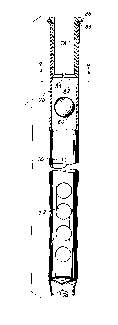
Fig. 1 is a side elevation view of the top portion of
the inner storage tank of a hot Water heater known in the
prior art.


A

.- . .' . . .

-' 2016295
--2--


FIG. ~ is a partial sectional view of a
portion of FIG. l.
FIG. 3 is a sectional view of the cold water
inlet heat trap fitting of FIG. l.
FIG. 4 is a sectional view taken along line
4-4 of FIG. 3.
FIG. 5 is a sectional view taken along line
5-5 of FIG. 3.
FIG. 6 is a side sectional view of the inner
storage tank of a hot water heater, and shows a dip
tube extending downwardly therein.
FIG. 7 is a view taken along line 7-7 of FIG.
6.
, PLC?Cnt Invcntio~
15 ~ FIG. 8 is a partial sectional view of a dip
tube modified in accordance with the invention and
including a heat trap therein.
FIG. 9 is a sectional view taken along line
9-9 of FIG. 8.
FIG. 10 is a sectional view showing mounting
of the dip tube of FIG. 8.
FIG. 11 is a view like FIG. lO and shows a
~urther embodiment.
DL. . AI LCD DG''CQI rTIOt]
-Prior ~rt
FIGS. 1 and 6 show a hot water heater 12
having an inner storage tank 14 for holding water to be
heated by a lower burner assembly 16 or electric
heating element or the like. Tank 14 is enclosed by an
insulating jacket and an outer shell (not shown).
I~aste products of combustion are exhausted upwardly
through flue 18. Cold water is introduced through cold
water inlet pipe 20 and dip tube 22 into tank 14, and
heated water exits through hot water outlet pipe 24.


- ~ ", . ,, ................. :, . -. ~.
~ - -:- : - : .; :

~016~19~
--3--


Tank 14 has a pair of spuds 26 and 28 welded
to the top external surface thereof, for example as
shown at weldment 30 for spud 26, FIG. 2. The cold
water inlet includes an external heat trap fitting 32
which is threadingly connected at its lower end to spud
26, and threadingly connected at its upper end to cold
water inlet pipe 20. Storage tank 14 has an opening
34, FIG. 2, receiving an annular dip tube retainer 36
having an upper flange 38 trapped between the top of
tank 14 and the lower inner beveled surface 40 of spud
26. Retainer 36 has an aperture 42 through which dip
tube 22 is extended downwardly during installation
until stopped by enga~ement of upper flared flange 44
against the edge of opening 42 of retainer 36. Heat
trap fitting 32 is threaded downwardly into spud 26
until the lower end of fitting 32 engages the top of
dip tube 22 at flared flange 44.
Heat trap fitting 32 includes a movable
sealing ~ember provided by a ball 46, FIG. 3, having a
density less than 1.0 such that it floats in water.
When tank 14 is full, ball 46 floats upwardly into
enga~ement with beveled valve seat 48 at the lower end
of inner sleeve 50. This prevents heat loss upwardly
through pipe 20. Slots 52 extending radially through
the cylindrical sidewall of sleeve 50 at valve seat 48
and provide pressure relief. Another sleeve 54 has a
plurality of lower radial spokes 56, FIGS. 3 and 5,
stopping and holding ball 46 during incoming water
flow. The water flows around ball 46 and through lower
passages 58 between spokes 56. The incoming water
f1Ows downwardly through~dip tube 22 and is discharged
at lower holes 60, FIG. 6, in the dip tube. The bottom
of the dip tube is crimped at 62 in a cross-shaped
pattern, FIG. 7, to close the lower end thereof. Upper
hole 64 in the dip tube is an anti-siphon hole.


. . . - - - - '

4 201629~


The hot water outlet of the tank includes a
heat trap fitting 66 with a ball having a density
greater than 1.0, such that the ball sinks in water and
closes a lower valve seat, to prevent heat loss, for
example as shown in above noted Nickel U.S. Patent
4,286,573. Heat trap fitting 66 is similar to heat
trap fitting 32, but inverted.
rc~cnt Invcntion
~ FIG. 8 shows a dip tube 70 modified in
accordance with the present invention. Dip tube 70 is
a cylindrical tube of given diameter extending
downwardly into tank 14 and has a plurality of lower
holes 72 for discharging water into the tank, a lower
closed crimped end 74, and an upper anti-siphon hole
lS 76, all as comparable to dip tube 22. An inner
cylindrical tubular insert 78 extends downwardly a
given distance into dip tube 70. A sealing member is
provided by ball 80 having a density less than 1.0 such
that it floats in water. Ball 80 has a diameter less
than the inner diameter of dip tube 70 and greater than
the inner diameter of tubular insert 78. Lower crimped
end 74 of dip tube 70 provides a lower stop in the dip
tube spaced below the bottom end 82 of insert 78. Ball
80 is movable longitudinally upwardly and downwardly in
dip tube 70 between the bottom end 82 o~ insert 78 and
lower stop 74. ~all 80 floats in water upwardly into
engagement with bottom end 82 of insert 78 to close
same and prevent heat loss upwardly through and out of
dip tube 70 and to prevent convection water currents
upwardly through and out of dip tube 70. Ball 80 moves
downwardly out of engagement with bottom end 82 of
insert 78 in response to incoming water flowing through
~nsert 78 and downwardly in dip tube 70.
Bottom end 82 of insert 78 is beveled
comparably to beveled valve seat 48 in FIG. 3, and also


, ., ., . - .. - . . ~ - . -


. -: . . ,. : - , ,
,, :. . :. . ~ . . -

201629~
--5--


includes slots 84 extending radially through the
cylindrical sidewall of insert 78 to relieve pressure
therethrough from the storage tank and the dip tube
when the valve seat at bottom end 82 is closed. When
ball 80 is seated against bottom end 82 of insert 78,
there is still limited communication between the
interior of dip tube 70 below ball 80 and the interior
of tubular insert 78 above ball 80. In an alternative
embodiment, pressure relief is provided by a porous
ball 80.
Tubular insert 78 has an upper portion 86
extending above the upper end 88 of dip tube 70 and
flared radially outwardly to form a flange extending
radially beyond dip tube 70. During installation, dip
lS tube 70 is inserted downwardly through opening 42, FIG.
10, in dip tube retainer 36 until stopped by engagement
of flange 86 against retainer 36. Cold water inlet
pipe 90 is threaded downwardly into spud 26 until the
bottom end 92 of the pipe engages flange 86 in tight
sealing relation. ~ip tube 70 and tubular insert 78
are preferably polypropolyene. In an alternative
embodiment, FIG. 11, an annular sealing gasket 94 may
be provided between flange 86 and retainer 36. Insert
78 is pressed into dip tube 70 with a tight
interference fit to retain dip tube 70 on insert 78 and
to prevent water from creeping back up along the
interface therebetween.
The modified dip tube in accordance with the
present invention enables a cold water inlet pipe to be
threaded directly into spud 26 without an extra fitting
for a heat trap as at 32. The heat trap function is
instead performed in the dip tube. This eliminates the
cost of a separate external heat trap fitting otherwise
required for such function. This cost reduction is
significant in high sales volume water heaters.

r . .
.; ~ .


2~l~2~


The invention.also locates the travel stroke
of ball 80 entirely within storage tank 14 to reduce
noise caused by movement of ball 8q. In the prior art,
movement of ball 46 in the external piping is audible
as a faint tapping sound, which may be objectionable in
various applications. The present invention solves
this problem.

Representative Drawing
A single figure which represents the drawing illustrating the invention.
Administrative Status

For a clearer understanding of the status of the application/patent presented on this page, the site Disclaimer , as well as the definitions for Patent , Administrative Status , Maintenance Fee  and Payment History  should be consulted.

Administrative Status

Title Date
Forecasted Issue Date 1997-11-18
(22) Filed 1990-05-08
(41) Open to Public Inspection 1990-11-09
Examination Requested 1993-03-17
(45) Issued 1997-11-18
Deemed Expired 2009-05-08

Abandonment History

There is no abandonment history.

Payment History

Fee Type Anniversary Year Due Date Amount Paid Paid Date
Application Fee $0.00 1990-05-08
Registration of a document - section 124 $0.00 1990-10-24
Maintenance Fee - Application - New Act 2 1992-05-08 $100.00 1992-05-08
Maintenance Fee - Application - New Act 3 1993-05-10 $100.00 1993-03-11
Maintenance Fee - Application - New Act 4 1994-05-09 $100.00 1994-03-01
Maintenance Fee - Application - New Act 5 1995-05-08 $150.00 1995-03-30
Maintenance Fee - Application - New Act 6 1996-05-08 $150.00 1996-02-14
Maintenance Fee - Application - New Act 7 1997-05-08 $150.00 1997-03-13
Final Fee $300.00 1997-06-24
Maintenance Fee - Patent - New Act 8 1998-05-08 $150.00 1998-04-15
Maintenance Fee - Patent - New Act 9 1999-05-10 $150.00 1999-05-04
Maintenance Fee - Patent - New Act 10 2000-05-08 $200.00 2000-05-03
Maintenance Fee - Patent - New Act 11 2001-05-08 $200.00 2001-04-20
Maintenance Fee - Patent - New Act 12 2002-05-08 $200.00 2002-04-17
Maintenance Fee - Patent - New Act 13 2003-05-08 $200.00 2003-04-22
Maintenance Fee - Patent - New Act 14 2004-05-10 $250.00 2004-04-21
Maintenance Fee - Patent - New Act 15 2005-05-09 $450.00 2005-04-20
Maintenance Fee - Patent - New Act 16 2006-05-08 $450.00 2006-04-18
Maintenance Fee - Patent - New Act 17 2007-05-08 $450.00 2007-04-17
Owners on Record

Note: Records showing the ownership history in alphabetical order.

Current Owners on Record
A.O. SMITH CORPORATION
Past Owners on Record
THREATT, GARY S.
Past Owners that do not appear in the "Owners on Record" listing will appear in other documentation within the application.
Documents

To view selected files, please enter reCAPTCHA code :


To view images, click a link in the Document Description column. To download the documents, select one or more checkboxes in the first column and then click the "Download Selected in PDF format (Zip Archive)" or the "Download Selected as Single PDF" button.

List of published and non-published patent-specific documents on the CPD .

If you have any difficulty accessing content, you can call the Client Service Centre at 1-866-997-1936 or send them an e-mail at CIPO Client Service Centre.


Document
Description 
Date
(yyyy-mm-dd) 
Number of pages   Size of Image (KB) 
Cover Page 1994-06-25 1 23
Abstract 1994-06-25 1 17
Claims 1994-06-25 3 134
Drawings 1994-06-25 3 121
Description 1994-06-25 8 307
Description 1997-02-05 8 284
Claims 1997-02-05 3 126
Cover Page 1997-11-17 1 42
Drawings 1997-02-05 3 128
Representative Drawing 1997-11-17 1 6
Office Letter 1993-03-29 1 52
Prosecution Correspondence 1993-03-17 1 26
Prosecution Correspondence 1997-06-24 1 39
Prosecution Correspondence 1992-04-08 2 44
Fees 1997-03-13 1 55
Fees 1996-02-14 1 51
Fees 1995-03-30 1 63
Fees 1994-03-01 1 36
Fees 1993-03-11 1 45
Fees 1992-05-08 1 29