Note: Descriptions are shown in the official language in which they were submitted.
fi ~
L~.~JJ AND APPARI~TlJ2~ FOR ~NIlFACTl~RING
Reference may be made to Applicant's two commonly-
assigned and related ~pplications filed simultaneously
herewith, 2,016,369 and 2,016,371.
R~ IND OF 1~ INVDlTION
The present invention concerns a method and apparatus for
manufacturing a fibre-reinforced material. Specifically the present
invention concerns a method and apparatus for manufacturing
fibre-reinforced material, which is formed by a reinforcing bundle or
bundles bonded with a matrix forming resin material in such a way
that the individual fibres are surrounded by resin material.
The main problem in the manufacture of products of this kind
is the high viscosity of some matrix forming materials. Because the
individual fibres in the fibre bundles are very close to each other,
it is thereby difficult for the resin material to penetrate into the
bundle to surround all individual fibres. However such penetration
is necessary in view of the desired properties of the product, such
as strength, stiffness, chemical resistance etc.
Many methods have been tried to solve the problem. In one
solution fibre bundles are transferred through a so-called cross-head
die, in such molten or liquid resin is penetrated into the fibre
bundles moving through the die. In the so-called powder method a web
of fibre bundles is transferred through a bed of dry thermoplastic
resin particles, whereby the web of fibre bundles carries along resin
particles, which at a later stage are melted in the fibre bundle.
There are also solvent methods in which fibre bundles are impregnated
with resins dissolved in a liquid medium.
--1--
CA 02016370 1998-11-18
The cross-head die method has proven to be ineffective in
the impregnation of fibre bundles with thermoplastic resin because
all individual fibres will not be surrounded by resin material.
Powder methods have been proven to necessitate a multiplicity of
processing stages which are difficult to synchronize, are expensive
to purchase and operate while damaging the reinforcement. In solvent
methods a drying process is required which is expensive, causes
environmental problems, is time-consuming and limits the production
rate. Furthermore the quality of the product is low due to voids
left after the removal of solvents.
8~Y OF TE~ INVBNTION
The present invention provides a method and apparatus for
impregnating reinforcing fibres in the form of fibre bundles so that
individual fibres are surrounded by bonding resin. The invention is
based on the known phenomena that some pseudoplastic materials being
subjectable to shear stresses experience a decrease in viscosity.
This phenomena, known as "shear thinning", is common for various
emulsions, dispersions, suspensions and other materials including
melts of thermoplastic resins and in minor degree also solutions of
thermoset resins. The degree of this shear thinning response can be
altered with the level of shear stress applied to the material. At
low stresses a small amount of thinni"g is achieved, at intermediate
shear stresses the amount of shear thinning increases dramatically,
while at very high stresses the amount of thinning reverts to low
levels as the material approaches minimum viscosity.
A typical range of viscosity for thermoplastic resin melts
is 102-106 PaS and for thermostat resin solution 100-5000 PaS.
In the impregnation of reinforcing fibres a range of 1-10 PaS is
ideal, a common magnitude is 102 PaS and in some cases 103 PaS
--2--
CA 02016370 1998-11-18
can be acceptable. Typical shear rate ranges for polymer melts and
solutions are 10 l_lo 6 1/S and ranqe of maximum response can be
10~-104 1/S.
The method according to the invention comprises the step of
impregnating of fibre bundles with molten or liquid resin while
manufacturing a fibre-reinforced material, which material comprises a
fibre bundle or bundled groups of fibres having each fibre surrounded
by matrix resin, by impregnating a continuous web of one or more
fibre bundles with a molten or liquid resin and solidifying said
resin by cooling or a chemical reaction. The method of the invention
is characterized in that before said impregnation the molten or
liquid resin material is made subject at shear forces by forcing it
to flow through a channel ending at an impregnation point, said
channel containing at least one section having decreasing
cross-section and~or said channel having a cross-section sufficiently
narrow to cause shear forces decreasing the viscosity of the molten
or liquid resin material.
According to an advantageous embodiment of the method of the
invention the molten or liquid resin material is fed to the
impregnation point through a capillary feed pipe, which ends at the
impregnation point through one or more feed openings.
According to one embodiment of the invention the feed
openings have circular, rectangular or other cross-sections.
With the method of the invention it is possible to
manufacture any fibre-reinforced material, in which the fibres are in
the form of bundles. the fibres can be any kind of fibres bondable
by a matrix resin. Such products are for example fibre-reinforced
granules for injection molding and other processes, prepregs or
preimpregnated materials for conventional processes such as
- CA 020l6370 l998-ll-l8
.
extrusion, filament winding, tape laying etc.
Suitable fibres to be used in the invention are glass
fibres, carbon fibres and aramid fibres and thermoplastic fibres.
Common reinforcing fibre materials are glass fibre products in the
form of bundles, which can be used as single bundles or also in the
form of woven products, for example as glass fibre rovings.
Typically glass fibre bundles contain thol~An~ of individual fibres
with a diameter of 10-17~m.
The resin material to be used for bonding fibre-reinforced
products can be a thermoplastic resin, which is impregnated into
fibre bundles as melt, or a thermosetting resin, which will be
solidified after impregnation with heat or chemical reaction.
Suitable thermoplastic resins are among others olefine
homogeneous polymers and copolymers, vinyl chloride homogeneous
polymers and copolymers, polyethylene terephtalate, acrylonitrile
homogeneous polymers, polymers and copolymers, polyamides or
copolyamides, thermoplastic polymers or formaldehyde, polycarbonate,
polysulphone and mixtures of two or more of any of the polymers above
or in general any other thermoplastics which show decreased viscosity
by shearing action.
The invention concerns also an apparatus for impregnating
reinforcing fibres in the form of fibre bundles so that individual
fibres are surrounded by bonding resin. The apparatus according to
the invention is characterized in that it comprises means for moving
a web of a continuous fibre bundle or bundles past an impregnation
point and means for feeding molten or liquid resin to said
impregnation point through a channel, which contains at least one
section having decreasing cross-section and/or which has a
cross-section sufficiently narrow to cause shear forces decreasing
CA 02016370 1998-11-18
the viscosity of the molten or liquid resin material.
According to an advantageous embodiment of the invention
said means for feeding molten or liquid resin to the impregnation
point comprise a capillary feed pipe, which ends at the impregnation
point in the impregnation head through one or more feed openings
formed into the wall of the impregnation head.
According to an advantageous embodiment of the invention
said feed openings have circular, rectangular or other cross-section.
According to an advantageous embodiment of the invention
said feed openings consist of one or more slits cut into the wall of
said impregnation head.
According to an advantageous embodiment of the invention
said impregnation head is connected to the outlet of an extruder.
According to an advantageous embodiment of the invention the
outer surface of the impregnation head is curved or planar within the
area of impregnation.
BRIFF D~K~ ON OF T~F DRA~ING~
The invention will be further illustrated but not limited by
referring to Figures, in which
Fig. 1 is an elevational view, partly in section, of an
apparatus according to the invention applied for manufacturing
continuous fibre-reinforced thermoplastic granules.
Fig. 2 is a schematic illustration of the impregnation head
for impregnating a web of glass fibre bundles with matrix resin
CA 02016370 1998-11-18
according to the invention.
Fig. 3 is a more detailed view of the impregnation head
according to the invention.
Figs. 4 and 5 are two end views for the impregnation head of
Fig. 3.
Fig. 6 is a general view of the impregnation head according
to the invention attached to an extruder.
Fig. 7 is a detailed perspective view of the impregnation
head showing several feed openings having a round cross-section for
supplying molten thermoplastic resin to the impregnation point.
Fig. 8 is a detailed perspective view of the impregnation
head showing one slit-like feed opening for supplying molten
thermoplastic resin to the impregnation point and
Fig. 9 is a detailed perspective view of the impregnation
head showing two slit-like feed openings having a round cross-section
and opening to different sides of the impregnation head for supplying
molten thermoplastic resin to the impregnation point.
~K~K~V EMBOD~ 8 OF TH~ INVBNTION
In Fig. 1, a web 10 of glass fibre bundles is supplied from
a drum 11 through a preheating chamber 12 and a spreading device 13
into an impregnation head 18. In the spreading device 13 the web 10
is transported via a series of valves 14, so that the fibre
alternately runs over and under the valves 14. This device spreads
the bundles of fibres to some extent and thus facilitates the
impregnation stage. However, it should be noted that the use of a
spreading device 13 is not necessary in any way and does not form a
part of the invention. The impregnation head 18 is connected to an
extruder 15, into which the resin material 16 to be impregnated is
fed through a hopper 17. In the extruder 15 the resin is melted and
CA 02016370 1998-11-18
is formed to be ready to be fed to the impregnation head 18 according
to the invention.
The resin impregnated web lOb or band of fibre bundles is
then transferred to a cooling unit 19, where the molten resin is
solidified by cooling. The solidifying can also take place by
chemical reaction, wherein the impregnated resin may contain the
additives necessary for the solidifying and in the solidifying
additional heating can be used, if necessary.
From the cooling unit 19 the resin impregnated and hardened
fibre bundles are then transferred to a chopper 20, which cuts the
impregnated web to pieces 21 of proper length, which are ready for
packing or further treatments. With the method and apparatus of the
invention it is naturally possible also to prepare also continuous
fibre-reinforced products, which in that case are cut in respective
desired lengths or are left completely uncut.
Transportation of the fibre bundles web 10 through the
apparatus in Fig. 1 can be carried out by any suitable pulling
device. A belt-driven pulling device 22 is schematically illustrated
in Fig. 1.
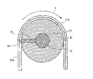
In Fig. 2 there is disclosed an impregnation head 30, inside
which there is a capillary feed channel 31. The resin 32 to be
impregnated is pumped through this capillary channel 31 and thus the
resin is subjected to shear forces, which lower its viscosity. From
the capillary channel 31 a feed opening 33 extends to the outer
surface of the impregnation head 30 at an impregnation point 34. The
web of fibre bundles lOa travels in the direction marked with arrow A
past this impregnation point 34, whereby the resin having lowered
viscosity penetrates to the web lOa. The impregnated web is marked
with lOb.
CA 02016370 1998-11-18
In Fig. 3 there is disclosed a more detailed drawing of the
impregnation head 30. The impregnation head 30 can be attached to an
extruder in point 33. A capillary feed channel 31 goes through the
impregnation head 30 to a slit-like feed opening 34, which opens to
the surface of the impregnation head at point 35. The resin from the
extruder flows through the feed channel 31 into the direction of
dash-lined arrow B and its viscosity will be lowered by shear forces
in the capillary channel 31.
Fig. 4 is a cross-section of the impregnation head 30 in
Fig. 3 viewed from the extruder side and Fig. 5 is a similar
cross-section viewed from the opposite side. As best seen in Fig. 5
the feed opening 34 can be a slit extending from the capillary
channel 31 to the impregnation point 35. Of course the feed opening
34 can just as well be formed by one or more cavities of other shape.
In Fig. 6 there is a general view of the impregnation head
30 attached to an extruder 15. The resin 16 to be impregnated is fed
to the extruder 15 through a hopper 17. In the extruder 15 the resin
is melted and consolidated and transported with the aid of a screw 36
to the outlet 33 of the extruder 15 and further to the capillary
channel 31. Also seen in this figure is the web lOb passing by the
impregnation point 35.
In Figs. 7 and 8 different shapes of the feed openings 33
have been disclosed. In Fig. 7 there are three openings 33 with a
circular cross-section. There can be one or several openings over
the width of the fibre bundle web. In Fig. 8 there is one slit-like
feed opening 33, the width of which is approximately the same as that
of the fibre bundle web. In Fig. 9 there is disclosed an embodiment,
in which there are two slit-like feed openings 33 opening to
different sides of the impregnation head 30. Of course there can be
016370
~:,
more than two slit-like feed openings. It is possible also in the
embodiment of Fig. 7 to use two or more groups of feed openings 33.
~:
~- Although the invention has been described above applied to
the impregnation of a moving fibre bundle web, it is evident that the
fibre bundle web can be stationary and the impregnation head can be
arranged to be movable. The function of the invention will be same
in both cases. Also, it is possible to use two or more impregnation
heads according to the invention and these impregnation heads can be
on the same or different sides of the fibre bundles web to be
impregnated.
f
:,
:~'
~' ~
_9_
: :~