Language selection

Search

Patent 2016421 Summary

Third-party information liability

Some of the information on this Web page has been provided by external sources. The Government of Canada is not responsible for the accuracy, reliability or currency of the information supplied by external sources. Users wishing to rely upon this information should consult directly with the source of the information. Content provided by external sources is not subject to official languages, privacy and accessibility requirements.

Claims and Abstract availability

Any discrepancies in the text and image of the Claims and Abstract are due to differing posting times. Text of the Claims and Abstract are posted:

  • At the time the application is open to public inspection;
  • At the time of issue of the patent (grant).
(12) Patent Application: (11) CA 2016421
(54) English Title: SOLENOID VALVE
(54) French Title: VANNE ELECTROMAGNETIQUE
Status: Deemed Abandoned and Beyond the Period of Reinstatement - Pending Response to Notice of Disregarded Communication
Bibliographic Data
(51) International Patent Classification (IPC):
  • F15B 13/043 (2006.01)
  • B60T 08/36 (2006.01)
  • B60T 08/50 (2006.01)
  • B60T 15/02 (2006.01)
(72) Inventors :
  • TACKETT, WENDELL DEAN (United States of America)
(73) Owners :
  • ROBERT BOSCH TECHNOLOGY CORPORATION
(71) Applicants :
  • ROBERT BOSCH TECHNOLOGY CORPORATION (United States of America)
(74) Agent: MACRAE & CO.
(74) Associate agent:
(45) Issued:
(22) Filed Date: 1990-05-09
(41) Open to Public Inspection: 1990-12-22
Examination requested: 1997-03-18
Availability of licence: N/A
Dedicated to the Public: N/A
(25) Language of filing: English

Patent Cooperation Treaty (PCT): No

(30) Application Priority Data:
Application No. Country/Territory Date
370,523 (United States of America) 1989-06-22

Abstracts

English Abstract


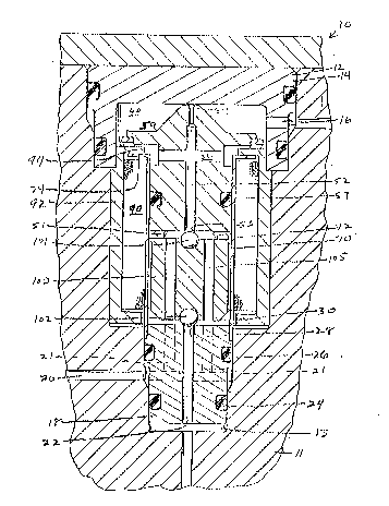
ABSTRACT OF THE DISCLOSURE
A solenoid valve (10) comprises a body (12)
received within a stepped opening (13) of a modulator body
(11). The solenoid valve (10) includes a first opening
(16) communicating with a chamber (40) and second (20)
and third (22) openings communicating with an interior
area (30) of the solenoid body (12). Located within the
chamber (40) is a shuttle valve (50) having a longitudinal
through-opening (52) with an orifice opening (54) and a
transverse opening (56) communicating with the chamber
(40) and intersecting the longitudinal through-opening
(52). An armature (100) is disposed within the interior
area (30) and has a first valve member (101) which may
seat sealingly with a valve seat (53) of the longitudinal
through-opening (52) of the shuttle valve (54), and a
second valve member (102) which may seat sealingly with a
valve seat (28) of the third opening (22). The armature
(100) has a pair of parallel axial through-passages (105).
The armature (100) and shuttle valve (50) are biased by a
spring (51) and each move reciprocally within the solenoid
body (12). The second opening (20) extends transversely
through the solenoid valve body (12) and intersects
orthogonally a pair of openings (21) which communicate
with the interior area (30) and are coaxially aligned
with the pair of axial through-passages (105) in the
armature (100). A coil (90) is disposed about the shuttle
valve (50) and armature (100). Energization of the coil
(90) causes the armature (100) to move and seat the first
valve member (101) within the valve seat (53) of the
longitudinal through-opening (52) and separate the second
valve member (102) from the third opening (22), thus
permitting fluid to flow from the second opening (20) to
the third opening (22). A pressure differential created
across the shuttle valve (50) and armature (100) causes
conjoint movement of the shuttle valve (50) and armature
5100) toward the third opening (22) so that fluid flow
from the chamber (40) directly to the transverse opening
(56) is substantially restricted and fluid in the chamber
(40) flows through the orifice opening (54).


Claims

Note: Claims are shown in the official language in which they were submitted.


- 6 -
CLAIMS
1. A solenoid valve, comprising a body having
at one end a first opening and at a second end second and
third openings, the first opening communicating with a
chamber located within said body, a shuttle valve disposed
reciprocably within said chamber and having a first ori-
fice opening communicating with a longitudinal through-
opening in the shuttle valve and a transverse opening
which extends transversely through the shuttle valve and
intersects the longitudinal through-opening, first resili-
ent means disposed between said shuttle valve and said
body in order to bias said shuttle valve toward a normal
position which permits fluid to flow past said resilient
means and to said transverse opening, an armature disposed
within said body and located between said first and third
openings, second resilient means disposed between said
shuttle valve and armature, the armature comprising a
reciprocably movable valve member having a pair of paral-
lel axial through-passages and at one end a first valve
member aligned with a valve seat of said longitudinal
through-opening of the shuttle valve and at the other end
a second valve member which sealingly engages a valve
seat of the third opening, the second opening in the body
communicating with said parallel axial through-passages
and an interior area of said body wherein said armature
is disposed, and coil means disposed within said body and
about said shuttle valve and armature, so that energiza-
tion of said coil means causes said first valve to seal-
ingly engage the valve seat of said longitudinal through-
opening and said second valve to disengage from the valve
seat of said third opening which then communicates with
said second opening, and a resulting pressure differential
across said shuttle valve and armature causing conjoint
movement of the shuttle valve and armature toward said
third opening so that fluid in said chamber flows through
said orifice opening.
2. The solenoid valve in accordance with claim
1, wherein said shuttle valve includes sealing means

-7-
disposed thereabout so that said chamber is isolated from
said interior area.
3. The solenoid valve in accordance with claim
2, wherein said second opening is disposed orthogonally
relative to said third opening.
4. The solenoid valve in accordance with claim
3, wherein said second opening includes perpendicular
portions which extend parallel to said third opening and
which are in approximate coaxial alignment with said
parallel axial through-passages.
5. The solenoid valve in accordance with claim
1, wherein said shuttle valve includes a laterally extend-
ing flange which provides a seat for said first resilient
means, displacement of said shuttle valve by the pressure
differential causing the first resilient means to be com-
pressed and fluid flow past said first resilient means
substantially restricted by said flange.
6. The solenoid valve in accordance with claim
5, wherein said shuttle valve includes at least one longi-
tudinal projection which may engage said armature and
effect a minimum separation therebetween.
7. The solenoid valve in accordance with claim
6, wherein said solenoid valve is inserted as an unit
within a stepped opening in a modulator body.
8. The solenoid valve in accordance with claim
7, wherein a second end of the body includes a pair of
seals thereabout so that said second opening is isolated
from said third opening.
9. The solenoid valve in accordance with claim
1, wherein the solenoid valve includes a generally cylin-
drical member receiving therein said shuttle valve and
armature, the cylindrical member having an end flange
extending radially outwardly to engage a radially extend-
ing flange of said body.
10. A solenoid valve, comprising a body having
at one end a first opening and at a second end second and
third openings, the first opening communicating with a

-8-
chamber located within said body, a shuttle valve disposed
movably within said chamber and having a first orifice
opening communicating with a longitudinal opening in the
shuttle valve and a transverse opening which intersects
the longitudinal opening, first resilient means disposed
between said shuttle valve and said body in order to bias
said shuttle valve toward an at rest position which per-
mits fluid to flow past said first resilient means and to
said transverse opening, an armature disposed within said
body and located between said first and third openings,
the shuttle valve and armature biased by second resilient
means, the armature comprising a reciprocably movable
valve member having parallel through-passages and at one
end a first valve member aligned with a valve seat of
said longitudinal opening of the shuttle valve and at the
other end a second valve member which sealingly engages a
valve seat of the third opening, the second opening in
the body communicating with said parallel through-passages
and an interior area of said body wherein said armature
is disposed, and coil means disposed within said body and
about said shuttle valve and armature, so that energiza-
tion of said coil means causes said first valve to seal-
ingly engage the valve seat of said longitudinal opening
and said second valve to disengage from the valve seat of
said third opening which then communicates with said
second opening, and a resulting pressure differential
across said shuttle valve and armature causing conjoint
movement of the shuttle valve and armature toward said
third opening so that fluid in said chamber flows pri-
marily through said orifice opening.
11. The solenoid valve in accordance with claim
10. wherein said second opening is disposed orthogonally
relative to said third opening.
12. The solenoid valve in accordance with claim
10, wherein said shuttle valve includes a laterally exten-
ding flange which provides a seat for said first resilient
means, displacement of said shuttle valve by the pressure

-9-
differential causing the first resilient means to be com-
pressed and fluid flow past said first resilient means
substantially restricted by said flange.
13. The solenoid valve in accordance with claim
12, wherein the solenoid valve includes a generally cylin-
drical member receiving therein said shuttle valve and
armature, the cylindrical member having an end flange
extending radially outwardly to engage a radially extend-
ing flange of said body, the flange of the body engaged
by the flange of the shuttle valve to restrict fluid flow
when the first resilient means is compressed.
14. The solenoid valve in accordance with claim
10, wherein said second opening includes perpendicular
portions which extend parallel to said third opening and
which are in approximate coaxial alignment with said
parallel through-passages.
15. The solenoid valve in accordance with claim
14, wherein said shuttle valve includes at least one
longitudinal projection which may engage said armature
and effect a minimum separation therebetween.
16. The solenoid valve in accordance with claim
15, wherein a second end of the body includes a pair of
seals thereabout so that said second opening is isolated
from said third opening.
17. The solenoid valve in accordance with claim
10, wherein said solenoid valve is inserted as an unit
within a stepped opening in a modulator body.

Description

Note: Descriptions are shown in the official language in which they were submitted.


~ ~ ~ 6 ~ 2 ~
SOLENOID VALVE
The present invention relates generally to a
solenoid valve, and in particular to a three-way solenoid
valve that may be utilized in an adaptive braking system.
Many solenoid valves have been provided pre-
viously for use in adaptive braking systems. ~.S. PatentNos. 4,620,565 and 4,790,351 illustrate such types of
solenoid valves. Solenoid valves which utilize a plunger
to push a ball valve off its valve seat tend to have a
reduced response time. The placement of the plunger in
the decay fluid flow path necessitates that the decay
passage be enlarged in order to provide for a certain
amount of flow. Enlargement of the decay path increases
the hydrostatic force acting on the ball due to the in-
creased dif~erential pressure area. Thus, this load must
be overcome by the solenoid and any increase in this load
results in a slower or larger solenoid valve. It is
desirable to remove the plunger from the decay path. A
resulting benefit of this is the subsequent reduction in
parts and complexity of the solenoid valve. It is also
desirable to have the armature located during adaptive
braking sy~tem operation within a location where the
optimum air gap is utilized so that the fastest possible
response for a valve of the particular type of design is
achieved. The initial movement of the armature of the
solenoid valve may be necessary to open a passageway to a
sump circuit so that brake fluid is decayed from the
brakes, with the resulting displacement of the armature
creating a larger air gap and a subsequent operation of
the armature at a location in the solenoid valve that is
less than the optimal range of operation due to the en-
larged air gap. It is desirable to have the armature
disposed, during adaptive braking system operation, with-
in the optimal range of operation so that the air gap is
minimized and the fastest response time for the valve is
achieved.
The present invention solves the aboYe problems
by providing a solenoid valve, comprising a body having
at one end a first opening and at a second end second and

2 ~ 2 .L
third openings, the first opening communicat:ing with a
chamber located within said body, a shuttle valve disposed
movably within said chamber and having a first orifice
opening communicating with a longitudinal opening in the
shuttle valve and a transverse opening which intersects
the longitudinal opening, first resilient means disposed
between said shuttle valve and said body in order to bias
said shuttle valve toward an at rest position which per-
mits fluid to flow past said resilient means and to said
transverse opening, an armature disposed within said body
and located between said first and third openings, the
shuttle valve and armature biased by second resilient
means, the armature comprising a reciprocably movable
valve member having parallel through-passages and at one
end a first valve member aligned with a valve seat of said
longitudinal opening of the shuttle valve and at the other
end a second valve member which sealingly engages a valve
seat of the third opening, the second opening in the body
communicating with said parallel through-passages and an
interior area of said body wherein said armature is dis-
posed, and coil means disposed within said body and about
said shuttle valve and armature, so that energization of
said coil means causes said first valve to sealingly
engage the valve seat of said longitudinal opening and
said second valve to disengage from the valve seat of said
third opening which then communicates with said second
opening, and a resulting pressure differential across said
shuttle valve and armature causing conjoint movement of
the shuttle valve and armature toward said third opening
so that f luid in said chamber flows primarily through said
orifice opening.
The invention will now be described by way of
e~ample with reference to the accompanying drawings in
which:
35Figure 1 illustrates the solenoid valve of the
present invention during normal braking;
Figure 2 illustrates the solenoid valve during
an initial stage of energization of the coil; and

Figure 3 illustrates the solenoid valve during
subsequent stages of coil energization.
The solenoid valve of the present invention is
indicated g~nerally by reference numeral 10 in Figure 1.
Solenoid valve 10 comprises a valve body 12 having at
body end 14 a first opening 16 which communicates with
the master cylinder or pump of an adaptive braking system
(not shown). It should be clearly understood that, through
other valving mechanisms, both the master cylinder and
pump of an adaptive braking system may communicate fluid
pressure to first opening 16. The opposite body end 1~
includes a second opening 20 which communicates with a
brake circuit and a third opening 22 which communicates
with a sump circuit of an adaptive brakin~ system. ~ppo-
site body end 18 includes a pair of seals 24 and 26 which
isolate the second and third openings from one another.
Third opening 22 extends longitudinally through body end
18 to valve seat 28 which communicates with an interior
area 30 of solenoid valve 10. Second opening 20 extends
transversely through body end 18 without intersectingthird opening 22, and communicates with a pair of perpen-
dicularly disposed longitudinal openings 21 which communi-
cate with the interior area 30.
Body end 14 defines a part of chamber 40 having
disposed therein a shuttle valve 50. Shuttle valve 50
includes a longitudinal through-opening 52 which includes
at one end an orifice opening 54 that communicates with
chamber 40. Transverse opening 56 extends transversely
through shuttle valve 50 and intersects longitudinal
through-opening 52. Shuttle valve 50 includes a radially
extending flange 58 which provides a seat for resilient
means 60 located hetween flange 58 and a flange 94 of the
body of solenoid valve 10. A cylindrical member 70 located
within body 12 has an interior opening 72 which receives
reciprocably shuttle valve 50. Shuttle valve seal 59
defines one end of chamber 40. Located between shuttle
valve 50 and an armature 100 is a spring~or resilient
means 51. Longitudinal through-opening 52 includes a

2 ~ 2 ~
-- 4
valve seat 53 opposite the orifice opening 54. Cylindrical
member 70 has a coil 90 disposed thereabout, the coil
located within an outer body member 92. Cylindrical
member 70 includes a radially extending flange 74 which
engages a radially extending flange 94 of outer body
member 92.
Located within interior opening 30 is the arma-
ture 100 which includes at one end a first valve member
101 that can seat sealingly with valve seat 53, and at a
second end a second valve member 102 which can seat seal-
ingly with valve seat 28. A pair of parallel axial
through-passages 105 extend through armature 100. Arma-
ture 100 may move reciprocably within interior opening
30. Spring 51 biases valve member 102 into sealing engage-
ment with valve seat 28. The body 12 of solenoid valve10 may be inserted as a unit within a stepped opening 13
of a modulator body 11.
During normal braking, fluid pressure is received
from the master cylinder via first opening 16. Fluid
pressure enters chamber 40 and flows around flange 58,
resilient means 60, to transverse opening 56 and longitu-
dinal through-opening 52. The fluid continues its flow
past open valve seat 53 to parallel axial through passages
105, to interior area 30, and then to openings 21 and
second opening 20 which communicates with the brake cir-
cuit. The fluid travels freely from first opening 16 to
second opening 20 in order to effect braking of the
vehicle. During normal braking, the third opening or sump
opening 22 i5 closed by second valve member 102. When an
electronic control unit (not shown) of an adaptive braking
system senses an incipient skidding condition, the elec-
tronic control unit effects energization of coil 90 which
causes armature 100 to be displaced upwardly against
spring 51 so that first valve member 101 engages sealingly
valve seat 53 (see Figure 2). This prevents any fluid
pressure at first opening 16, be it from the master cylin-
der or a simultaneously energized pump, from being com-
municated through opening 52. Simultaneous with the clos-
ing of valve seat 53, second valve member 102 opens valve

. 2 ~
seat 28 so that brake fluid pressure at second opening 20
can decay through openings 21 to interior area 30, past
valve seat 28, and through third opening 22 to the sump
circuit (not shown~. The reduced brake pressure present
within interior area 30 in combination with the hi~her
pressure present in cham~er 40 created by the pump trans-
mitting fluid pressure to first opening 16, causes a pres-
sure differential across shuttle valve 50 and armature
100. This pressure differential causes the shuttle valve
and armature to move conjointly downwardly so that resili-
ent means 60 is compressed (see Figure 3). The flange 58
of shuttle valve 50 engages flange 94 so that fluid pres-
sure in chamber ~0 is substantially restricted from com-
municating freely with transverse opening 56. This results
in fluid pressure within chamber 40 being communicated
through orifice opening 54 to the longitudinal through-
opening 52. Also, the armature 100 is moved downwardly
into the optimal operating range. When the shuttle valve
and armature move downwardly as a result of the pressure
differential, the magnetic facial area of armature 100 is
displaced downwardly after initial coil activation so
that armature lO0 operates at an optimum air gap and this
provides for the fastest possible response of the sole-
noid valve due to its operation within the optimal range
of operation. As shuttle valve 50 moves downwardly to
restrict free flow to transverse opening 56, armature lO0
is moved downwardly and may then modulate between valve
seats 28 and 53 to effect the build and decay functions
of the adaptive braking system operation.
The present invention provides advantageously for
a fast operating solenoid valve which does not require a
plunger disposed within the decay path, and provides an
armature disposed within the optimal range of operation
during adaptive braking system operation so that a fast
operational response is effected.

Representative Drawing
A single figure which represents the drawing illustrating the invention.
Administrative Status

2024-08-01:As part of the Next Generation Patents (NGP) transition, the Canadian Patents Database (CPD) now contains a more detailed Event History, which replicates the Event Log of our new back-office solution.

Please note that "Inactive:" events refers to events no longer in use in our new back-office solution.

For a clearer understanding of the status of the application/patent presented on this page, the site Disclaimer , as well as the definitions for Patent , Event History , Maintenance Fee  and Payment History  should be consulted.

Event History

Description Date
Inactive: IPC from MCD 2006-03-11
Time Limit for Reversal Expired 2000-05-09
Application Not Reinstated by Deadline 2000-05-09
Deemed Abandoned - Failure to Respond to Maintenance Fee Notice 1999-05-10
Inactive: Status info is complete as of Log entry date 1998-04-16
Inactive: Application prosecuted on TS as of Log entry date 1998-04-16
Request for Examination Requirements Determined Compliant 1997-03-18
All Requirements for Examination Determined Compliant 1997-03-18
Application Published (Open to Public Inspection) 1990-12-22

Abandonment History

Abandonment Date Reason Reinstatement Date
1999-05-10

Maintenance Fee

The last payment was received on 1998-02-19

Note : If the full payment has not been received on or before the date indicated, a further fee may be required which may be one of the following

  • the reinstatement fee;
  • the late payment fee; or
  • additional fee to reverse deemed expiry.

Patent fees are adjusted on the 1st of January every year. The amounts above are the current amounts if received by December 31 of the current year.
Please refer to the CIPO Patent Fees web page to see all current fee amounts.

Fee History

Fee Type Anniversary Year Due Date Paid Date
Request for examination - standard 1997-03-18
MF (application, 8th anniv.) - standard 08 1998-05-11 1998-02-19
Owners on Record

Note: Records showing the ownership history in alphabetical order.

Current Owners on Record
ROBERT BOSCH TECHNOLOGY CORPORATION
Past Owners on Record
WENDELL DEAN TACKETT
Past Owners that do not appear in the "Owners on Record" listing will appear in other documentation within the application.
Documents

To view selected files, please enter reCAPTCHA code :


To view images, click a link in the Document Description column (Temporarily unavailable). To download the documents, select one or more checkboxes in the first column and then click the "Download Selected in PDF format (Zip Archive)" or the "Download Selected as Single PDF" button.

List of published and non-published patent-specific documents on the CPD .

If you have any difficulty accessing content, you can call the Client Service Centre at 1-866-997-1936 or send them an e-mail at CIPO Client Service Centre.

({010=All Documents, 020=As Filed, 030=As Open to Public Inspection, 040=At Issuance, 050=Examination, 060=Incoming Correspondence, 070=Miscellaneous, 080=Outgoing Correspondence, 090=Payment})


Document
Description 
Date
(yyyy-mm-dd) 
Number of pages   Size of Image (KB) 
Claims 1997-05-12 4 176
Description 1993-11-05 5 230
Abstract 1997-05-12 1 34
Drawings 1993-11-05 2 79
Representative drawing 1999-07-15 1 33
Courtesy - Abandonment Letter (Maintenance Fee) 1999-06-06 1 186
Fees 1997-04-03 1 50
Fees 1995-03-28 1 68
Fees 1996-03-28 1 65
Fees 1994-04-27 1 72
Fees 1993-04-12 1 42
Fees 1992-05-05 1 24