Note: Descriptions are shown in the official language in which they were submitted.
20~68~)
IMPROVED THROTTLING VALVE
Field of the Invention
The present invention relates generally to an improved
design for a throttling valve which prevents deterioration of
valve surfaces. Specifically, the present invention i6
directed to the prevention of erosion and cavitation caused by
the sudden vaporization of liquids and following implosion of
these vapor bubbles.
~0'168
Backqround of the Invention
Throttling valves are used in the chemical, petroleum and
utility industries for a variety of high pressure drop
applications including continuous blow-down sampling, hi~h
pressure venting, turbine drain and boiler feed-pump bypass
relief. There are a wide number of applications for heavy duty
valves with critical service conditions. The damaging
conditions are normally not permanent. They typically occur
during transient operation and only a number of times per day
or per week. Typically, such valves have been utilized as high
and low pressure drain and preheating valves, reheater
application, reheater and superheater drain applications, steam
turbine, stop and throttle valve drains, and vent applications
Throttling valves have always been subject to rapid
deterioration due to erosion, cavitation damage and wire-
drawing in vital parts. Cavitation is the sudden creation and
collapse of vapor pockets within a rapidly moving liquid. One
type of throttling valve which minimizes such deterioration
employes a stellite disk and cylindrical seat coated with an
erosion resistant material. Fluid flowing through the annulu~
between the disc and seat accelerates smoothly until it reaches
the blunt end of the disk. At this point, the flow area
increases at the center of the f low path and the resultant
pressure drop at the core of the flow path causes vaporization
2016~ 3
to occur in the cylindrical seat within a layer of continuously
flowing unvaporized fluid along the wall of the seat.
A frequent problem encountered with such throttling valves
is that the pressure drop caused within the valve causes
vaporization and cavitation of the liquid medium as it passes
through the outlet of the valve. Cavitation frequently occurs
at locations along the surfaces of the throttling valve and
deteriorates those surfaces. Because of the design of the
disk and seat, a valve surface exposed to cavitation occurring
at the blunt end of the disk must be coated with a wear
resistant substance. The cost of coating the surfaces with a
wear resistant material can be expensive.
It would be desirable to provide a throttling valve which
can direct fluid away from the interior surfaces of the valve
housing and members so as to minimize the damage caused by
cavitation.
It would further be desirable to provide a throttling
valve with a contoured plug defined by a special exponential
equation which can direct the flow of material away from the
interior walls of valve surfaces.
It is therefore an object of the present invention to
provide a throttling valve specifically designed for severe
service which restricts the location of vaporization and
subsequent cavitation of a liquid medium away from valve
surfaces.
~:016~1Q
Another object of the present invention is to provide a
throttling valve which accelerates the flow of a liquid medium
through a passageway having a small cross-sectional area onto
one having a larger cross-sectional area, so that any
vaporization and cavitation occurs away from valve surfaces at
a defined location removed from the valve surfaces.
A further object of the present invention is to provide a
throttling valve which requires fewer valve surfaces to be
treated with a wear resistant coatings, thereby reducing the
cost of valve manufacture.
It is another object of the present invention to provide a
multi-purpose valve which can handle gases, liquids, mixtures
of water and steam or a slurry of liquid and abrasive material
without eroding and damaging the seat and plug.
It is still another object of the present invention to
provide a throttling valve which can accommodate cavitating and
flashing liquids, liquids containing suspended solids, and two
phase flow.
20~6~Q~
Summary of the Invention
In accordance with the present invention, a throttling
valve which prevents the deterioration of valve surfaces is
disclosed. The valve comprises a casing having an inlet
conduit for introducing a gas or liquid medium into the valve,
an outlet conduit for expelling a gas or liquid out of the
casing, and a valve opening for supporting a valve member. An
annular sealing member is situated withln the housing between
the inlet and outlet ports. The valve further includes a
retractable valve member slidingly housed within the valve for
opening and closing the fluid flow between the inlet and outlet
conduits, the valve member having a contoured nose defined by a
complex exponential e~uation which slidingly mates with said
6ealing means, said nose contour directing the output flow
toward the center of said outlet conduit. The valve of the
pre6ent invention has two configurations, a straight line and
an angular configuration. The straight line configuration
incorporates a hard coated protection plate in the outlet
section which can be removed.
6~
Brief Description of the Drawinqs
The foregoing summary, as well as the following detailed
description will be better understood when read in conjunction
with the drawings appended hereto. ~or the purpose of
illustrating the invention, there is shown in the drawings an
embodiment which is presently preferred, it being understood,
however, that this-invention is not limited to the precise
arrangement and instrumentalities shown.
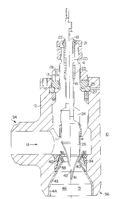
Figure 1 is a time lapse section view of the throttling
valve of the preferred embodiment in both the open and closed
position.
Figured 2 and 2A are graphs of the profile of the nose
section of the valve plug of the preferred embodiment.
Figure 3 illustrates the exponential formula for the plug
of the preferred embodiment.
Figure 4 is a section view of a second embodiment of the
invention.
zo~68~
Description of the Preferred Embodiment
The present invention is disclosed and described with
reference to the enclosed Figures wherein the same numbers are
used where applicable. Referring to Figure l, a cross-section
elevated view of a throttlinq valve lO in accordance with the
present invention is shown in both the open and closed
positions. The throttling valve lO of the present invention
has a body 12 which is constructed from forged or cast heat
resistant carbon steel. The valve configuration is of the
angle shape design and can be manufactured according to the
needs of a specific industry. Body 12 has an inlet conduit 13
and a prependicularly disposed outlet conduit 15 for
introducing a liquid medium into and out of the valve. The
valve body 12 further includes a bonnet 14 which is against
the pressure seal members by a locking nut 17. The locking nut
ic retained by a bolt 17a. The bonnet 14 is constructed from
heat resistant low alloyed carbon steel and has a hardened
guiding ring ll at the lower end which provides for vibration
free guidance of the plug. The axial portion of the bonnet 14
contains a bore 16 which retains a valve stem 18. The space
between the upper part of bore 16 and stem 18 is packed with a
packing 20 which is compressed by a hardened gland 22 which is
moved by the threaded packing nut 21. A guide bu6hing 23
Z016~
supports the valve stem. The bonnet is held in place by the
segment ring 27 and the support ring 25.
Bonnet 14 includes a cylindrical cavity 24 into which the
body of plug 26 extends when raised. The inlet conduit 13
extends from a side wall of the body 12 and is connected to a
source of liquid medium or slurry which enters into the valve.
Various types of substances may be channeled through the valve
including mixtures of water and steam or slurries of liquid and
abrasi~e materials.
The outlet conduit 15 is provided at a lower end of the
valve housing through which vaporized liquids are discharged.
Outlet conduit 15 is shaped as a conically expanding section.
Conically expanding outlet conduit 15 is protected against
secondary cavitation effects and abrasion by a stellite
hardfacing.
The valve housing includes an annular seal 32 which is
situated between the inlet and outlet conduits. The seal
comprises an inner annular seat 32 inserted within an outer
annular seat 34. Annular seats 32, 34 function as a seal when
plug 26 is in a closed position and as a passageway through
which a liquid medium is constantly accelerated in a downstream
direction when the plug i8 retracted in an open position. The
outer annular seat 34 i~ welded within the body 12 at a
location ad~acent to the outlet conduit. Inner annular seat 32
has an inner surface 36 which extends outwardly in an upstream
201~
direction from one end and a second inner surface 38 extending
outwardly in a downstream direction.
Because the inner annular seat 32 is removably displaced
within the outer annular seat 34, a gap 40 is formed between
the two respective seats. Gap 40 allows for the thermal
expansion of the inner annular seat 32 or distortion of body 12
when an extremely hot liquid medium or gas (500-1000F) is
passed through the valve 10 and over inner annular seat 32.
Further, when outer annular seat 34 is welded within the valve
body 12, it experiences thermal expansion caused by the
extremely high temperatures. Only the inner surfaces 36, 38
are coated with a highly wear resistant substance such as
tungsten carbide, chromium carbide or stellite. During
fabrication, the two seat parts are welded together, machined
and then inserted and welded into the body 12.
The valve plug 26 of the preferred embodiment is now
described. Valve plug 26 directs the flow of a liquid medium
to a specific location downstream of the inner annular seat 32.
In the present embodiment, valve plug 26 comprises a generally
cylindrical body connected at an upper end to the valve stem 18
with a nose section 42 at its lower end. The valve plug slides
up into the bonnet cavity by the valve stem. Nose section 42
comprises precisely contoured arcuate walls having a decreasing
angle of curvature relative to the central axis of the body 12.
The contour of the valve nose is defined by the graph shown in
Figure 2 and the following equation which is illustrated in
Figure 3. 20168~0
Y = A ~ (V - A~ x ~Wu/v-A)
U(Wutv-:-A) (V - X)
where:
A = D/2, where D is the diameter of the plug at its tip
V = S x Cl; U = S x C2
where Cl and C2 are constants such that Cl is a value between
0~1 and 5.0, and C2 is a value between 0.5 and 5.0; and
where S = the distance between the central plug axis and the
inner seat at its point of minimum diameter
w = C3, where C3 is a value between 0.1 and 2.0
X = stroke, where stroke is equal to the nominal size of the
valve.
The arcuate walls of the plug 26 direct the fl~w of liquid
medium away from the plug surface in a downstream direction,
thereby preventing its deterioration. Plug 26 may be made of a
ceramic material, and the contour should be coated with a very
thin and smooth layer of highly wear resistant Tungsten or
Chromium-Carbide 41. The seat flow path is hard-faced with a
material such as Stellite 6 or Haynes 25. The resulting liquid
flow velocity vector is directed away from the plug contour.
Plug 26 provides linear control characteristics with a very
small dead bandlin the beginning. The linear characteristic
results in reduced seat sizes and therefore lower gap leakage
rates. If the application requires an exponential
characteristic, it can be obtained with a cam in the positioner
or electronically.
The throttling valve 10 further includes an outlet conduit
15 which expands conically outward and has a greater cross-
~20~G~30~
s~ctional area than the inner annular seat 32. This area
provides a location where vaporization and subsequent
cavitation can occur. The outlet conduit 15 has primary walls
43 which extend outwardly from the inner annular seat 32 in a
direction towards the outlet conduit 15 and connected to
secondary waIls 44 which extend parallel to the central axis of
the valve housing. The walls of outlet conduit 15 are coated
with a highly wear resistant substance similar to that of the
first inner surface 32. Because of the difference in cross-
sectional areas between the inner annular seat 32 (and surfaces
36, 38) and the outlet conduit 15, a liquid medium traveling
over the inner annular seat 32 and into the cavity 15
experiences a large and sudden pressure drop coupled with a
subsequent decrease in velocity. This causes a liquid medium
at or near its saturation point to vaporize and cavitate. This
phenomenon is further aided by the fact that the liquid medium
is accelerated over the inner annular seat 32, as described
above. As a result, cavitation occurs at a specific location
within the valve housing 12 downstream of the plug 26, not in
the seat section which is specially treated to prevent
deterioration 43, 44.
Referring to Figure 4, an alternative Y-shaped inline
embodiment of the present invention is disclosed. In this
embodiment, the inlet and outlet ports are substantially
parallel and the plug and seat assembly extend transeversely
to the inlet and outlet conduit6. The body 12' is constructed
2~:)168~1~
of die forged or cast heat resistant low alloyed carbon 6teel.
The bonnet asse~bly 14' is identical to that of the first
embodiment. This embodiment includes a hard coated erosion
protection plate 58 in the outlet sectiGn. The plate is
retained by rin~s and is locked via a bolt 17a.
Operation
The operation of the present invention is now described
with reference to the attached Figures. The throttling valve
of the present invention acts as a control valve for severe
services utilizing gas, liquids, mixtures of water and steam
and slurries of liquids and abrasive materials under high
pressure and temperature. The throttling valve is designed to
protect valve surfaces from deterioration caused by erosion and
cavitation.
A liquid medium emerging from a source enters the
throttling valve 10 through the source input and conduit port
13. In a fully closed position, the nose portion of the plug
26 is engaged with the inner annular 6eat 32 forming a seal
which prevents any liquid from passing through the valve 10.
A conventional activator device forces longitudinal upward
movement of the valve stem 18 towards an open position, thereby
disengaging the plug 26 from the inner annular seat 32 and
allowing liquid to flow through the valve 10. The plug recedes
into the cavity of bonnet 14.
Liquid flowing through the input port 13 i6 directed
downwardly over the inner annular seat 32 by the no8e of the
12
2016~30~
plug, the contour of the which i6 defined by the following
exponential equation:
Y = A + ( V - _A ~ x ¦ Wll /V-A )
I~(wu/v-A) (U - X
where:
A = D/ 2, where D is the diameter of the plug at its tip
V = S x C1; U = S x C2
where C1 and C2 are constants such that C1 is a value between
0.1 and 5.0, and C2 is a value between 0.5 and 5.0; and
where S = the distance between the central plug axis and the
inner seat at its point of minimum diameter
W = C3, where C3 is a value between 0.1 and 2.0
X = stroke, where stroke is equal to the nominal size of the
valve,
As the liquid flows over the first inner surface 36 of
inner annular seat 32, it is continuously accelerated because
the cross-sectional area at inner surface 36 continuously
decreases. The velocity of the liquid medium is greatest when
it reaches the beginning of the second inner surface 38 of the
inner annular seat 32. The cross-sectional area over the
~econd inner surface 38 suddenly increases as it leads to
outlet conduit 15. Because of the sudden change in cross-
sectional areas between the first and second inner surfaces 36,
38, an abrupt pressure drop occurs, causing vaporization and
subsequent cavitation of the liquid medium at or near its
saturation point. The contoured shape of the nose section 42
direct the liquid flow and resultant cavitation into the cavity
46 downward and away from the surface of the nose 42.
20168(~
The bubbles formed as a result of the cavitation implode
within the cavity 46 whose walls are coated and protects them
from being deteriorated. The liquid and gas mixture i5 then
discharged through the output port.
In the present embodiment flanges 54 and 56 may be
provided at the inlet conduit 13 and the outlet conduit 15 as
seen in Fig. 1, and help connect the throttling valve.
However, depending on the system in which the valve will be
utilized, it should be understood that any suitable mounting
means can be employed.
The plug and seat assembly operate in a similar manner in
the alternative embodiment. However, the abrasion resistant
attachment plate 58 protects the valve body from the cavitating
liquid.
It will be recognized by those skilled in the art that
changes may be made to the above-described embodiment of the
invention without departing from the broad inventive concepts
thereof. It is understood, therefore, that this invention is
not limited to the particular embodiment disclosed, but it is
intended to cover all modifications which are within the scope
and spirit of the invention as defined by the appended claims.
14