Note: Descriptions are shown in the official language in which they were submitted.
20~7048 -
Method Or making a measuring tube for an electromagnetic
flow meter, and the measuring tube
The invention relates to a method of making a measuring tube for an
electromagnetic flow meter comprising a tube member of non-magnetic
metal such as stainless steel, metal electrodes arranged in through-
passages, and a continuous lining of`meltable electrically non-
conductive material covering the inner circumferential surfaces of the
tube member and throughpassages, and to a measuring tube which has in
particular been made according to this method.
Measuring tubes of the kind here in question are known from C~-PS 20 68
122. In that case, the lining consiqts of a thick glass layer which
also extends with a reduced thickness along the wall of the through-
passages. The metal electrode terminates in the middle of the wall of
the tube member. The electric connection to the interior of the tube
is made with the aid of a molten-in plug of electrically conductive
glass with a similar chemical structure as that of the lining. There
are no directions as to manufacture. In particular, there is a danger
of intermerging flow and mixing of the two glasq compositions which
differ only with respect to their electric behavour.
The invention is based on the problem of providing a measuring tube
with a continuous insulating lining of the aforementioned kind that
_l _
~0170~8
can be made in a simple manner and with a reproducibility suitable for
mass production.
This problem is solved according to the invention by the method steps
a) that the electrodes are qo fixed in the throughpasqageq that they
project inwardly beyond the inner surface of the tube member,
b) that the inner surface of the tube member and the entire gap
between each electrode and the associated throughpassages are
provided with an enamel priming slip,
c) that the end face of the electrodes is cleared of the enamel
priming slip, and
d) that the priming enamel i~ melted by heating and then cooled
again.
When introduclng the enamel prlming slip, lt is lnevltable for the end
faces of the electrodes to become at least partially covered by it.
The cleaning step ensures that the end face of the finished measuring
tube will produce a direct conductive connection to the fluid to be
measured. Since the electrode projects inwardly, it can be easily
cleaned and, in the finished measuring tube, it will pass through the
enamel layer.
The priming enamel cannot only be selected for its properties so that
it adheres well to the material of the tube member and is compatlble
therewlth aq far a~ temperature expanslon iq concerned. The qlip can
~ ~3~ ~0170~8
also be set with regard to its viscosity so that it forms a layer when
applied to the inner face of the measuring tube and at the same time
penetrates the gap between each electrode and the associated through-
passage without running out of the latter again. Further, the specific
weight of the slip can be set so that the volume of the slip introduced
into the gap will be reduced by no more than a permissible extent
during melting. The continuous priming enamel layer so formed produces
a measuring tube that meets high requirements.
The following additional method steps are particularly favourable:
e) that the inner surface of the tube member coated with the priming
enamel is provided with a slip of covering enamel,
f) that the end face of the electrodes is cleaned of the slip of
covering enamel,
g) that the covering enamel slip is melted by heating and subsequent-
ly cooled again.
The covering enamel can be selected to be different from the priming
enamel that produces the continuous electric insulation, so that it
will be adapted to a particular application. Thus, it may form a
coating which is resistant to acids or bases. It may be selected so
that it will not influence the fluid to be measured, which is, for
example, important in the food industry. In addition, the covering
layer may compensate the thickness of the lining if the priming enamel
_ _4_ 20170~8
layer is only thin because of its low viscosity required to penetrate
into the gap.
A preferred possibility of performing the method step b) or e) is to
close one end of the tube member and, if the closure is at the bottom,
to fill it with the slip, whereupon the slip is poured out leaving
behind the part~ adhering to the tube member. Thi~ leads to a uniform
coating and certain filling of the gap between the electrode and
throughpassage.
It is advisable for the qlip to be dried after the stated method step.
Even short drying periods of fractions of a minute are sufficient to
improve the viscosity and adhesive to such an extent that the applic-
ation will not be detrimentally influenced during subsequent cleaning.
For the cleaning itself, there are a multltude of pos~ibilities. In
particular, a brush or a carrier provided with an abrasive may be
introduced into the tube member.
Adhesion is improved if all the parts to be covered with enamel and at
least the inner face of the tube member are roughened before the method~
step a). A roughness of more than 3.2 ~m is recommended.
It is also favourable for the tube member to be anne~led without stress
prior to method step a). This prevents the enamel layers from fractur-
ing subsequently as a result of stresses caused by temperature
influences.
- 20170~8
Advantageously, the priming enamel slip is set to a much lower viscos-
ity than the covering enamel slip. This ensures that the priming
enamel slip is sure to penetrate into the gap between the electrode
and throughpassage and yet an adequate thickness of enamel layer is
produced everywhere.
A measuring tube for an electromagnetic flow meter comprising a tube
member of non-magnetic metal such as stainle~s steel, metal electrodes
arranged in throughpassages, and a continuous lining of m~:ltable
electrically non-conductive material covering the inner surfaces of
the tube member and the throughpassages and made in particular accord-
ing to the previously described method is characterised according to
the invention in that the lining consi~ts of a continuous priming
enamel layer which covers the inner faces of the tube member and the
entire gap between each electrode and the associated throughpassage,
and a covering enamel layer which covers the inner surfaces of the
priming enamel layer, the electrodes projecting beyond the inner
surfaces of the tube member, passing through both enamel layers and
having an end which is free from enamel.
Such a measuring tube has a continuous electric insulation, an adequate
thickness of enamel layer everywhere, good contact between the metal
electrode and the medium to be measured, and good adaptability to the
material of the tube member and to the fluid to be measured.
In particular, the electrodes may project radially inwardly beyond the
- -6- 20~70~8
enamel layers. This permits careful cleaning of the end faces of the
electrodes without the slip application being detrimentally influenced.
In addition, the projecting electrode parts produce eddies in the
fluid to be measured so that subsequent soiling will be prevented.
In a preferred example, the thickness of the priming enamel layer is
only a fraction of the gap width and the thickness of the covering
enamel layer. The thinness of the priming enamel layer results from
the viscosity required for penetration of the slip into the gap and is
balanced out by the thickness of the covering enamel layer.
It is also recommended that the inner surface of the tube member at
the ends is provided with a respective inwardly projecting circum-
ferential rib of which the radialheight iq substantially equal to the
thickness of both enamel layers. In this way, a uniform thickness of
enamel is ensured up to the ends of the tube member.
The mounting of the electrode required during production of the measur-
ing tube can be removed after production. However, it often facilit-
ates handling if the mounting is left on the measuring tube.
Such a conqtruction can be so that the electrode is held in an
electrically non-conductive plug inserted in a sleeve attached to the
tube member.
It is in this case recommended that the sleeve be of steel, be welded
into the tube member and form the throughpassage. An acid proof steel
~7~ 20~7U i8 -
should be used so that it meets all requirements.
The plug may be of ceramic. Since sealing is effected by the enamel
in the gap surrounding the electrode, it is sufficient for the ceramic
plug to hold the electrode mechanically.
Preferred examples of the invention will now be described in more
detail with reference to the drawing wherein:
ig. 1 is a longitudinal section through a measuring tube made in
accordance with the invention,
Fig. 2 is an enlarged representation of detail A in Fig. 1,
Fig. 3 is a modification of one end of the tube, and
Fig. 4 shows a modified form for the electrode attachment.
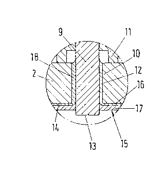
The measuring tube 1 in Fig. 1 comprises a tube member 2 of non-
magnetic stainless steel. At the ends, it carries two connecting
flanges 3 and 4. Two further inwardly disposed flanges 5 and 6 serve
to secure the measuring tube in an outer sleeve and the interposed
saddle coils.
Two electrode arrangements 7 and 8 provided on opposed sides have the
same construction as will be described in conjunction with Fig. 2. A
20~70~8
rod-form metal electrode 9 passes through a throughpassage 10 and is
held in two parts by a holder 11 in the illustrated central poqition
so that a concentric gap 12 remain~ between the electrode and the
inner surface of the throughpassage. The end face 13 of the electrode
9 projects radially inwardly beyond the inner surface 14 of the tube
member 2.
A lining 15 consists of a priming enamel layer 16 and a thicker cover-
ing enamel layer 17. In the gap 12 there is a priming enamel layer 18
which is continuous with the layer 16.
Both enamel layers are electrically insulating. The priming enamel
layer is adapted to the material of the measuring tube 2 as far as
thermal expansion is concerned and is adequately adherent with respect
thereto. The covering enamel layer 17 consists of an enamel which is
adapted for the particular application.
The following procedure may be a(l~ d for manufacture:
1 The tube member 2 of stainless steel is annealed in order to
make it stress free.
2. All parts are degreased. Their surface is roughened by sand
blasting or etching. The inner surface 14 of the tube member 2
should have a roughness greater than 3.2 ~m.
3. The electrodes 9 are mounted on the tube member 2 with the aid
_ _9_ 2017048
of the holders 11 so that they pro~ect inwardly beyond the inner
~urface 14 of the tube member 2.
4. A primlng enamel slip has its vi~c08ity set so that it still
penetrates into the gap 12 during application. This also defines
the thickness of the subsequent priming enamel layer 16.
5. The priming enamel is applied to the inner surface 14 of the
tube member 2 and filled into the gap 12. This can, for example,
be effected in that the tube member 2 is closed at the flange 3,
filled completely with the priming enamel slip and the latter is
finally poured out again. A defined amount of priming enamel
slip then remains on the inner surface 14 and in the gap 12.
6. The priming enamel slip is dried in an airing cupboard, for
example for 20 minutes. This leads to an increase in the viscos-
ity Ol- the slip and to corresponding stronger adhesion to the
tube member 2.
7. The end face 13 is cleaned of priming enamel slip adhering there-
to. This can be done with a brush or with a carrier provided
with abrasive, for example a sponge.
8. The whole is then heated in an oven and the priming enamel flows
together. In a practical test, heating lasted eight minutes and
took place up to 820 C.
- -lO- 20170~8
9. A covering enamel slip has its viscosity set so that lt will
later provide the desired thickness of layer.
10. This covering enamel slip is applied to the priming enamel slip
16. Thls can again take place so that the tube member 2 is
closed at one end, filled with this covering enamel slip, where-
- upon the latter is poured out again.
11. The covering enamel slip is dried in an air drying cupboard.
12. The excess covering enamel slip is removed from the end 13 of
the electrode 9.
13. The whole is again heated in an oven until the covering enamel
flows together.
14. The mountings 11 are removed.
15. The finished measuring tube is tested for leakproofness in a
leakage test.
In one embodiment, the priming enamel layer 16 had a thickness of 0.06
to 0.07 mm and the gap 12 had a width of 0. 5 mm. The covering enamel
layer had a thickness of 0.23 to 0.24 mm so that the lining 15 had a
total thickness of 0.3 mm. The electrode 13 pro~ected by 0.7 mm beyond
the inner surface 14 of the tube member 2, i.e. by 0.4 mm beyond the
lining 15.
-ll- 2017048
Whereas the thickness of the lining 15 decreases at the ends, the Fig.
3 modification shows that the tube member 102 has an inner circumfer-
ential rib 120 at its flange 103. In this way, the lining 115 can
retain a uniform thickness up to its ends. This avoids pockets and
the like in which dirt might accumulate. This is of interest in the
food industry.
In the Fig. 4 embodiment, a sleeve 221 of acid proof steel is welded
into a tube member 202. The sleeve carries a ceramic plug 222 serving
as a holder for the electrode 209. The gap 212 i9 now formed between
the electrode 209 and the inner surface of the sleeve 221. The applic-
ation of the priming enamel layer 216, the gap filling 218 and the
covering enamel layer 217 takes place in the same way as was described
in conjunction with Figs. 1 and 2.
In one embodiment, the priming enamel was a glass enamel and the cover-
ing enamel was a glass enamel with chromium oxide pigments. Such
enamels are conventional in the trade. The temperature coefficient of
the priming enamel was between that of the tube member and that of the
covering enamel, so that det~chment of the enamel during heating is
avoided.